EP0273673A1 - Organe coulissant pour câble de sécurité et soutien pour un tel câble - Google Patents
Organe coulissant pour câble de sécurité et soutien pour un tel câble Download PDFInfo
- Publication number
- EP0273673A1 EP0273673A1 EP87311267A EP87311267A EP0273673A1 EP 0273673 A1 EP0273673 A1 EP 0273673A1 EP 87311267 A EP87311267 A EP 87311267A EP 87311267 A EP87311267 A EP 87311267A EP 0273673 A1 EP0273673 A1 EP 0273673A1
- Authority
- EP
- European Patent Office
- Prior art keywords
- tube
- arm
- cable
- track
- slot
- Prior art date
- Legal status (The legal status is an assumption and is not a legal conclusion. Google has not performed a legal analysis and makes no representation as to the accuracy of the status listed.)
- Granted
Links
- 230000008878 coupling Effects 0.000 title claims abstract description 45
- 238000010168 coupling process Methods 0.000 title claims abstract description 45
- 238000005859 coupling reaction Methods 0.000 title claims abstract description 45
- 238000009434 installation Methods 0.000 claims description 15
- 238000004873 anchoring Methods 0.000 description 4
- 238000006073 displacement reaction Methods 0.000 description 3
- 230000002093 peripheral effect Effects 0.000 description 3
- 238000010276 construction Methods 0.000 description 2
- 239000000463 material Substances 0.000 description 2
- 239000004677 Nylon Substances 0.000 description 1
- 208000027418 Wounds and injury Diseases 0.000 description 1
- 230000006835 compression Effects 0.000 description 1
- 238000007906 compression Methods 0.000 description 1
- 230000006378 damage Effects 0.000 description 1
- 230000000694 effects Effects 0.000 description 1
- 208000014674 injury Diseases 0.000 description 1
- 239000002184 metal Substances 0.000 description 1
- 238000012986 modification Methods 0.000 description 1
- 230000004048 modification Effects 0.000 description 1
- 229920001778 nylon Polymers 0.000 description 1
- 239000004033 plastic Substances 0.000 description 1
- 229920003023 plastic Polymers 0.000 description 1
- 230000000717 retained effect Effects 0.000 description 1
- 239000011435 rock Substances 0.000 description 1
- 238000007493 shaping process Methods 0.000 description 1
- 230000035939 shock Effects 0.000 description 1
- 238000003466 welding Methods 0.000 description 1
Images




Classifications
-
- A—HUMAN NECESSITIES
- A62—LIFE-SAVING; FIRE-FIGHTING
- A62B—DEVICES, APPARATUS OR METHODS FOR LIFE-SAVING
- A62B35/00—Safety belts or body harnesses; Similar equipment for limiting displacement of the human body, especially in case of sudden changes of motion
- A62B35/0081—Equipment which can travel along the length of a lifeline, e.g. travelers
- A62B35/0087—Arrangements for bypassing lifeline supports without lanyard disconnection
-
- A—HUMAN NECESSITIES
- A62—LIFE-SAVING; FIRE-FIGHTING
- A62B—DEVICES, APPARATUS OR METHODS FOR LIFE-SAVING
- A62B35/00—Safety belts or body harnesses; Similar equipment for limiting displacement of the human body, especially in case of sudden changes of motion
- A62B35/0043—Lifelines, lanyards, and anchors therefore
- A62B35/0056—Horizontal lifelines
-
- A—HUMAN NECESSITIES
- A62—LIFE-SAVING; FIRE-FIGHTING
- A62B—DEVICES, APPARATUS OR METHODS FOR LIFE-SAVING
- A62B35/00—Safety belts or body harnesses; Similar equipment for limiting displacement of the human body, especially in case of sudden changes of motion
- A62B35/04—Safety belts or body harnesses; Similar equipment for limiting displacement of the human body, especially in case of sudden changes of motion incorporating energy absorbing means
Definitions
- This invention relates to apparatus comprising support means for locally supporting a safety track member in spaced relation to a fixed structure, and coupling means for coupling a load to such track member.
- Apparatus of this kind is useful for example in fall-arrest safety installations wherein a safety cable is strung above a work site and workers' individual safety belts or harnesses are coupled to that cable.
- Another use for apparatus as above referred to is in installations comprising a load-transporting cable which is guided for movement along a predetermined path and which carries coupling means to which a load can be connected.
- the design of apparatus of the kind referred to involves the problem that the coupling means coupled to the cable must be able to travel along the path of the cable without being obstructed by cable support means located at intervals along such path.
- This apparatus comprises a wheel having means by which it can be connected to the cable while leaving the wheel free to rotate about an axis transverse to the path of the cable, and the wheel has a series of peripheral recesses which serve in conjunction with guide means associated with the wheel to permit a device attached to the cable to travel past the wheel.
- the present invention provides an alternative solution to the problem above referred to and affords certain advantages in regard to simplicity of construction.
- apparatus comprising support means for locally supporting a safety track member in spaced relation to a fixed structure, and coupling means for coupling a load to such track member, said support means and said coupling means being constructed and arranged to enable said coupling means to pass said support means during travel of said coupling means along the path of said track member, characterised in that either said support means or said coupling means comprises an arm for attachment to a said fixed structure or to a load as the case may be, whereas the other of said support and coupling means comprises (i) a tube which defines a passageway for said track member, such tube being peripherally interrupted along its length by a slot which is wide enough to allow said arm to pass therealong, and (ii) a bearing part which rotatably supports said tube but so as to allow said arm to pass by such bearing part; at least one end of said tube being shaped so that axial abutment pressure of said arm against said end causes rotation of the tube to bring the adjacent end of said slot into line with such arm.
- Apparatus according to the invention can be of relatively simple construction, while being very reliable in use.
- the invention includes an installation comprising apparatus as above defined in combination with a safety track member, which member can for example be in the form of a flexible cable or a rail.
- a safety track member which member can for example be in the form of a flexible cable or a rail.
- the installation may include a plurality of said coupling means
- the safety track In installations as just referred to the safety track can be fixed.
- a fixed safety track is normally employed in fall-arrest safety installations, which is the most important field of use for the invention.
- the coupling means In the case that the safety track is fixed, the coupling means must be freely movable along such track.
- the slot of the rotatable tube preferably follows along the tube a path which over at least part of its length is inclined to planes containing the axis of the tube.
- the reason for this preference is that it avoids or reduces any tendency for the track member to become wedged in or to be forced out of the slot under loading forces on the track member.
- the strength requirements for the tube material are therefore less.
- the path of the slot follows a curve from one end of the tube to the other. That path, considered from either end of the tube, may wind unidirectionally around the tube axis, i.e. it may follow a generally helical path. Alternatively the path may wind first in one direction around part of the tube periphery and then in the reverse direction. This latter configuration enables the tube to be shorter for a given slot inclination.
- the angular extent of the bearing part which rotatably supports the slotted tube is such that said bearing part leaves an unobstructed by-pass gap which is substantially wider than the arm (belonging to the track support means or the coupling means) which extends into that gap during traverse of the coupling means past the track support means.
- the importance of this feature lies in the fact that the coupling means does not have to be in one particular angular relationship to the support means in order for such traverse to be possible. On the contrary such traverse can occur whatever be the relative angular orientation of the different means within a certain range which is determined by the width of the said by-pass gap. This is an important consideration in many safety installations.
- the bearing part supporting the rotatable tube leaves a said by-pass gap which subtends an angle of at least 80° about the tube axis.
- the safety track support means may comprise a track-supporting arm which is hinged to a base plate or other fixing portion of such support means so that any loading force exerted on the track member out of line with the hinge axis causes the track member to rock about such axis.
- the support means tends naturally to assume an orientation which will allow passage of the coupling means past the track support means even if the aforesaid by-pass gap is not much wider than the arm which has to pass along it.
- each end of the rotatable tube it is necessary for each end of the rotatable tube to be shaped to convert local axial pressure against that end into a turning moment causing rotation of the tube. Automatic rotation of the tube into by-pass position will then take place regardless of which end of the tube is subjected to axial abutment pressure by the arm of the support means or the coupling means as the case may be.
- This will normally be necessary when a load, e.g. a safety line attached to a worker's safety harness, has to be free to move to and fro along the safety track.
- a load e.g. a safety line attached to a worker's safety harness
- circumstances may occur in which a load has only to be moved in one direction parallel with the safety track and in those circumstances the special shaping is required at one end only of the tube. As an example of such circumstances.
- the coupling means of apparatus can be coupled to a safety track in the form of an endless driven cable which passes around drums or sheaves at feed and delivery ends of a transportation path and which is supported by track support means as hereinbefore referred to at at least one position along its course.
- a load to be transported can be connected to said coupling means when it is at the beginning of one reach of the cable and detached from such coupling means on reaching the delivery end of that reach.
- the coupling means attached to the cable always travels past the cable supporting means in one direction.
- the installation comprises a strung cable 1 which is secured to a fixture 2. At intervals along its length the cable is locally supported by cable-supporting members 3. Each of such members comprises a tubular head portion 4 having tapered end portions 7,7 ⁇ .
- the head portion 4 is integral with or connected to one end of an arm 5 the other end of which is connected to a fixing plate 6 which is secured to a fixed structure 2.
- the cable 1 has been threaded through the head portion 4.
- a component 8 from which a safety line can be suspended is coupled to the cable 1.
- This component constitutes the second component of the apparatus according to the invention.
- This component comprises a tube 9 through which the cable 1 has been threaded.
- the internal diameter of this tube is in excess of the external diameter of the head portion 4 of the cable-supporting component 3.
- the component 8 further comprises an arm 10 having an arcuate bearing part 11 which embraces but does not grip the tube 9 at a central zone thereof which is of reduced external diameter and forms a peripheral groove 12 in which the bearing part is accommodated.
- the tube 9 is thus rotatably supported by the bearing part 11 while being held against axial displacement relative thereto.
- the bearing part 11 subtends an angle which is greater than 180° but significantly less than 360° so that between its edges 13,14 there is an unobstructed gap for the passage of the arm 5 of the component 3 as hereinafter described.
- an aperture 15 (Fig. 4) through which a hook on a safety line attached to a safety harness can be engaged.
- the wall of tube 9 is peripherally interrupted by a slot 16 which follows a helical course from one end of the tube to the other.
- This slot has a width in excess of the diameter of the arm 5 of the cable-supporting component 3.
- Each end 9 ⁇ of tube 12 is profiled so as to provide guide edges which are inclined towards the slot.
- Fig. 1 the component 8 is shown with the tube 9 co-axial with the cable 1. In fact, until it reaches the head portion 4 of component 3, the inside of the tube bears on the cable 1. When the leading end of tube 9 reaches component 3, the leading end of the tube is caused to ride up over the head portion 4 by its tapering end portion 7 ⁇ . If the leading end of the slot 16 in the tube 9 happens to be in line with the arm 5 of the cable-supporting component 3 when the tube reaches that arm, the arm will directly enter that slot.
- Fig. 2 shows the tube 12 at a stage towards the end of its traverse over the head portion 4 of the component 3.
- Fig. 3 is a view from below, showing an earlier stage, when the arm 5 is at the entrance to the slot 16.
- the arm 5 offers no obstruction to the passage of the arcuate bearing part 11 of the component 8 provided that this component 8 is orientated so that the lines of motion of the boundary edges 13, 14 of the mouth of that bearing part are to opposite sides of the arm 5.
- the width of that mouth is substantially greater than the parallel cross-sectional dimension (diameter) of the arm 5 and in the specific illustrated embodiment the arm 5 will in fact offer no obstruction to the passage of the bearing part 11 provided that the component 8 is orientated so that its arm 10 is within about 50° from the vertical.
- the component will always have an orientation within this range during the normal intended use of the apparatus.
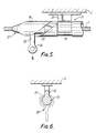
- the cable-supporting component 17 comprises a longitudinally slotted tube 18 which is rotatably supported in a bearing part 19 on an arm 20.
- the tube and bearing part are identical with the tube 9 and bearing part 11 of the apparatus shown in Figs 1 to 4.
- the bearing part 19 and its arm 20 form part of a bracket by which the component 17 is secured to a fixture 2.
- the coupling component 21 in Fig. 5 comprises a tubular head portion 22 through which the cable 1 extends and an arm 23 having an eye 24 for connection to a safety line.
- the coupling component must be freely slidable along the cable.
- the head portion 22 of the coupling component 21 is secured to the cable, e.g. by swaging or by clamping screws.
- Apparatus according to the invention can be of such form that it can be used in conjunction with a safety cable or with a safety track in the form of a rail.
- the apparatus described with reference to Figs 1 to 5 would function in the same way if the cable 1 were replaced by a substantially rigid metal bar or tube.
- Fig. 6 shows apparatus according to the invention specifically designed for use with a rail.
- a rail member 25 is locally supported by an arm 26 which forms part of a bracket for securing to a fixture 2.
- the arm 26 can be integral with the rail member or it can be separately fabricated and secured to the rail member by welding or in any other suitable manner.
- the coupling component 27 is similar to the coupling component 8 shown in Figs. 1 to 4.
- the longitudinally slotted tube 28 of component 27 slides along the rail member 25.
- the cable 1 is supported at intervals along its length by supporting members 30 comprising an arm 31 which is pivotally connected to a bracket 32 by a rivet 32 ⁇ .
- the bracket 32 is secured to a fixture 2.
- the cable 1 passes through a tubular head portion 33 of the arm 31.
- the head portion 33 is connected to the inner part of the arm by thin connecting webs 34.
- the tubular head portion 33 has tapered end extension pieces 35,36 of plastics material. Each of these pieces comprises a longitudinally slotted tube having at its wider end an internal annular rib which is snap-fitted into an external peripheral groove 37 on the tubular portion 33.
- Component 38 comprises a body 39 in which a tube 40 is rotatably mounted.
- the tube 40 has end portions of reduced diameter on which nylon bearing rings 41,42 are fitted.
- the tube and bearing rings are inserted, as an assembly, endwise into a passageway in the body 39, to bring bearing ring 42 into abutment with a shoulder near one end of such body.
- the assembly is retained in that passageway by a retaining plate 43 which is fitted over the opposite end of the tube and secured to the body 39.
- the wall of the said passageway in the body 39 does not completely surround the periphery of the tube 40.
- a gap 44 is left between opposed parts of such wall.
- the link or hook H is engaged with an arcuate slot 45 provided in body 39 at a region opposite the gap 44.
- the link or hook is freely movable along slot 45.
- the link or hook assumes a position against one or the other end of the slot 45, depending on the direction in which the safety line tends to be pulled by movement of the person to whom the safety line is attached.
- the tube 40 has an internal diameter in excess of the external diameter of the tubular head portion 33 of the cable supporting member 30. Like the tube 9 of the component 8 in Figs. 1-4, the tube 40 is peripherally interrupted by a slot. However, the slot 46 in tube 40 winds first in one direction and then in the reverse direction around part of the periphery of the tube, as appears in Fig. 9. Each end of the tube is profiled so as to provide inclined guide edges 47 which are inclined towards the ends of the slot.
- each of these webs has tapered edges 48. If the tube 40 reaches the web with the slot 46 and the web in register, the web enters the slot as the movement of the component along the cable 1 continues, and the tube 40 becomes rotated first in one direction and then in the opposite direction by the pressure of the two webs against the sides of the slot. If the slot 46 arrives at a web 34 out of register therewith, the web is struck by the inclined end edge 47 of the tube and this edge acts as a cam to cause the tube to rotate into a position in which the web enters the slot.
- the webs 34 can only pass along the slot 46 if they are also in register with the gap 44 in the body 39 of component 38. Because the arm 31 of the cable-supporting member 30 is freely pivotable relative to the fixed bracket 32, if a pull is exerted on the cable 1, in the vicinity of the arm 31 and in a direction such as to impose a turning moment on that arm, the arm tends to swing about its pivotal axis so that it becomes approximately aligned with the direction of the pull. Consequently the arm 31 tends naturally to assume a position such that the webs 34 are in the path of the said gap 44 in the body 39 of component 38.
- the width of the gap 44 is however preferably significantly greater than the thickness of the webs 34 so as to provide ample alignment tolerance.
- Figs 11 and 12 show a cable tensioning and anchoring device for connecting an end of cable 1 to a fixture.
- the device comprises a tubular casing 50 to which a cable end fitting 41 is connected by connecting pieces 52. An end portion of cable 1 is secured in this end fitting, e.g. by swaging or by clamping screws.
- a bar 53 extends axially through the casing 50 and the end of this bar which projects from the rear end of casing 50 is connected to or integral with an arm 54 having a terminal eye 55 for the passage of a bolt (not shown) by means of which the device can be anchored to a fixture.
- Another section of the length of bar 53 projects from the front end of casing 50 and is externally threaded.
- a tension adjustment nut 56 is screwed onto this part of the bar. Behind nut 56 is a ring 57 and between this ring and the front end of the casing 50 there is a shock-absorbing compression spring 58.
- the cable 1 is tensioned to a required extent by rotating the nut 56.
- Advance of the nut towards the right in the aspect of Fig.11 causes axial displacement of casing 50 and cable end fitting 51 in the same direction, thereby increasing the cable tension.
- Reverse movement of the nut has the opposite effect.
- the shock load transmitted to the cable via the safety line will be absorbed by the spring 58 which will accordingly serve to protect the worker from serious injury due to very abrupt arrest of the fall.
- the worker's safety line will itself have shock-absorbing properties.
- the cable tensioning and anchoring device allows a coupling component such as 38 (Fig.7) to be threaded onto the cable 1 at one end while the cable remains anchored.
- a coupling component such as 38 (Fig.7)
- the connecting pieces 52 which connect the cable end fitting 51 to the casing 50 are thin enough to pass along the gap 44 and slot 46 in component 38.
- the cable tensioning and anchoring device incorporates two safety catches 59, 60, one of which is shown in elevation in Fig.12. Each catch has an aperture 61 through which the bar 53 passes, and a hook portion 62 which engages around the cable end fitting 51.
- first catch 60 and then latch 59 is temporarily swung, against the biasing action of a torsion spring (not shown), into a position in which the hook portion 62 is disengaged from the end fitting 51 and the component 38 is passed along the end fitting past that catch, which is then released to return to its operative position.
- the torsion spring associated with each catch extends from a point 64 on the catch to a point on the casing 50.
- shock-absorbing means can be incorporated in the cable-supporting members, e.g. between the arm 31 and bracket 32 in Fig. 7, for absorbing load in the event that the coupling member is in engagement with such a supporting member at the time of a fall.
Landscapes
- Health & Medical Sciences (AREA)
- General Health & Medical Sciences (AREA)
- Business, Economics & Management (AREA)
- Emergency Management (AREA)
- Emergency Lowering Means (AREA)
- Supports For Pipes And Cables (AREA)
Applications Claiming Priority (2)
| Application Number | Priority Date | Filing Date | Title |
|---|---|---|---|
| GB8630787 | 1986-12-23 | ||
| GB868630787A GB8630787D0 (en) | 1986-12-23 | 1986-12-23 | Fall-arrest cable attachments |
Publications (2)
| Publication Number | Publication Date |
|---|---|
| EP0273673A1 true EP0273673A1 (fr) | 1988-07-06 |
| EP0273673B1 EP0273673B1 (fr) | 1991-09-18 |
Family
ID=10609527
Family Applications (1)
| Application Number | Title | Priority Date | Filing Date |
|---|---|---|---|
| EP87311267A Expired EP0273673B1 (fr) | 1986-12-23 | 1987-12-22 | Organe coulissant pour câble de sécurité et soutien pour un tel câble |
Country Status (6)
| Country | Link |
|---|---|
| US (1) | US4790410A (fr) |
| EP (1) | EP0273673B1 (fr) |
| JP (1) | JPH0759253B2 (fr) |
| CA (1) | CA1297848C (fr) |
| DE (1) | DE3773158D1 (fr) |
| GB (2) | GB8630787D0 (fr) |
Cited By (24)
| Publication number | Priority date | Publication date | Assignee | Title |
|---|---|---|---|---|
| EP0486411A1 (fr) * | 1990-11-16 | 1992-05-20 | Alain Mounier | Dispositif de sécurité pour chemin de circulation |
| WO1992020407A1 (fr) * | 1991-05-21 | 1992-11-26 | Barrow Hepburn Sala Ltd | Appareil d'arret de chute |
| EP0622091A1 (fr) * | 1993-04-28 | 1994-11-02 | Tractel S.A. | Système et dispositif de sécurité pour le transfert de charges |
| WO1998035724A1 (fr) * | 1997-02-12 | 1998-08-20 | Latchways Plc | Systeme de securite d'altitude |
| FR2774297A1 (fr) * | 1998-02-05 | 1999-08-06 | Somain | Dispositif de securite notamment pour toiture de batiment |
| FR2775605A1 (fr) * | 1998-03-06 | 1999-09-10 | Odco | Dispositif de securite anti-chute, notamment pour la protection des personnes executant des travaux en hauteur |
| WO1999055425A1 (fr) * | 1998-04-23 | 1999-11-04 | Latchways Plc | Systeme de securite en altitude |
| NL1010740C2 (nl) | 1998-12-07 | 2000-06-08 | Ziet Verder Beheer B V | Valbeveiligingssysteem en trolley voor toepassing in een dergelijk systeem. |
| WO2000047285A1 (fr) * | 1999-02-08 | 2000-08-17 | Latchways Plc. | Dispositif de fixation pour cable de securite |
| WO2002092171A1 (fr) * | 2001-05-11 | 2002-11-21 | Latchways Plc. | Coulisseau et support de cable de sauvetage |
| WO2003045504A1 (fr) * | 2001-11-27 | 2003-06-05 | Latchways Plc | Support de cable de securite |
| WO2005044380A1 (fr) * | 2003-10-30 | 2005-05-19 | Latchways Plc | Systeme antichute |
| AT500493A1 (de) * | 2003-05-13 | 2006-01-15 | Innotech Arbeitsschutz Gmbh | Vorrichtung zum befestigen einer persönlichen schutzausrüstung an einer seilführung einer absturzsicherung |
| WO2006125783A1 (fr) | 2005-05-24 | 2006-11-30 | Capital Safety Group Emea | Procede de montage d'un cable de ligne de securite sur un tendeur |
| WO2008020215A1 (fr) * | 2006-08-16 | 2008-02-21 | Uniline Safety Systems Limited | Support intermédiaire pour un élément de sécurité allongé |
| EP1900394A1 (fr) * | 2006-09-18 | 2008-03-19 | Comercial Igena, Sa | Support intermediaire pour une ligne de sécurité |
| EP2243981A1 (fr) * | 2009-04-22 | 2010-10-27 | Repapress AG | Dispositif de sécurité pour un parcours aventure en forêt |
| GB2473209A (en) * | 2009-09-02 | 2011-03-09 | Latchways Plc | Bracket fixing for a fall arrest safety line comprising a bolt held captive in a box structure. |
| US7921967B2 (en) | 2005-04-01 | 2011-04-12 | Capital Safety Group Emea | Energy-absorbing device |
| WO2011101781A1 (fr) * | 2010-02-19 | 2011-08-25 | Speedrunner Gmbh | Systeme de ligne d'assurage continue |
| US8061482B2 (en) | 2005-05-24 | 2011-11-22 | Capital Safety Group Emea | Tensioner for safety line with energy absorption device |
| FR2961875A1 (fr) * | 2010-06-29 | 2011-12-30 | Lr Etanco Atel | Tendeur de cable a chariot et absorbeur - tendeur pour ligne de vie comportant un tel tendeur. |
| DE102012205309B4 (de) * | 2012-03-30 | 2015-08-13 | Bornack Gmbh & Co. Kg | Seilaufhängung an Bäumen/Stangen |
| WO2018215842A1 (fr) * | 2017-05-23 | 2018-11-29 | Spanset Inter Ag | Fixation de câble et élément de passage formant coulisse |
Families Citing this family (44)
| Publication number | Priority date | Publication date | Assignee | Title |
|---|---|---|---|---|
| JPH0190567U (fr) * | 1987-12-07 | 1989-06-14 | ||
| GB9011370D0 (en) * | 1990-05-22 | 1990-07-11 | Barrow Hepburn Sala Ltd | Energy-absorbing bracket |
| US5002152A (en) * | 1990-05-29 | 1991-03-26 | Lebow Dwight R | Fall restraint cable support and method |
| US5105907A (en) * | 1990-05-29 | 1992-04-21 | Lebow Dwight R | Fall restraint cable support and method |
| JPH0756037Y2 (ja) * | 1990-07-28 | 1995-12-25 | 憲治 川部 | 張設ロープへの掛止補助具 |
| US5417303A (en) * | 1993-03-16 | 1995-05-23 | Bell; Michael | System and method for extending a safety line over an electrical transmission tower |
| US5350037A (en) * | 1993-05-24 | 1994-09-27 | Skymaster, Inc. | Workperson safety restraint system |
| GB2300215B (en) * | 1995-04-26 | 1999-03-24 | Simon Rood | Safety apparatus |
| US5687812A (en) * | 1995-06-05 | 1997-11-18 | The United States Of America As Represented By The Secretary Of The Air Force | Aircraft safety wash rack |
| US5979599A (en) * | 1996-12-17 | 1999-11-09 | Noles; Larry J. | Track transport system, track-support bracket, and track-traveling apparatus |
| GB2338506A (en) * | 1998-06-19 | 1999-12-22 | Latchways Plc | Safety line clamping device |
| GB2347278A (en) * | 1998-06-19 | 2000-08-30 | Latchways Plc | Intermediate support for cable, safety line or rail |
| AU749846B2 (en) | 1998-10-23 | 2002-07-04 | D B Industries, Llc | Energy absorbing connector |
| US6260661B1 (en) | 1998-10-23 | 2001-07-17 | Capital Safety Inc. | Safety line mounting methods and apparatus |
| US6056085A (en) * | 1998-10-23 | 2000-05-02 | Capital Safety Inc. | Anchorage methods and apparatus |
| EP1036575B1 (fr) | 1999-03-16 | 2004-05-12 | Protecta International | Méthode et dispositif d'ancrage d'une corde de sécurité |
| FR2804708B1 (fr) * | 2000-02-03 | 2002-03-15 | Dalloz Fall Prot | Dispositif de fixation d'une ligne de vie contre une paroi |
| US6273844B1 (en) | 2000-08-25 | 2001-08-14 | Paradigm Health Systems International, Inc. | Unloading system for therapy, exercise and training |
| FR2813800B1 (fr) * | 2000-09-13 | 2002-10-11 | Dalloz Fall Prot | Coulisseau pour ligne de vie |
| US6604605B2 (en) | 2001-01-11 | 2003-08-12 | Sala Group Pty Limited | Safety line anchorage methods and apparatus |
| GB2375366A (en) * | 2001-05-11 | 2002-11-13 | Latchways Plc | Safety line and shuttle arrangement |
| GB0227914D0 (en) | 2002-11-29 | 2003-01-08 | Protecta Internat Sa | Safety apparatus |
| GB2403256B (en) * | 2003-06-27 | 2006-02-15 | Latchways Plc | Safety line anchor |
| WO2005038168A1 (fr) * | 2003-10-14 | 2005-04-28 | Poldmaa, Kathleen | Navette de liaison |
| ES2389481T3 (es) * | 2003-10-21 | 2012-10-26 | Uniline Safety Systems Limited | Dispositivo anticaídas y sistema que incorpora el mismo |
| GB0328937D0 (en) * | 2003-12-13 | 2004-01-14 | Checkmate Uk Ltd | Lifeline trolley |
| JP4596950B2 (ja) * | 2005-03-28 | 2010-12-15 | 東日本旅客鉄道株式会社 | 水平移動用金具 |
| US20090260919A1 (en) * | 2005-05-13 | 2009-10-22 | Latchways Plc. | Safety line anchor |
| BE1016931A4 (nl) * | 2005-06-14 | 2007-10-02 | Exponent Challenge Technology | Verbeterde meelopende valbeveiliging met flexibele ankerlijn. |
| EP2155338B9 (fr) * | 2007-06-13 | 2012-06-13 | Exponent Challenge Technology, coöperatieve vennootschap met beperkte aansprakelijkheid | Ensemble antichute |
| DK178145B1 (da) * | 2008-03-05 | 2015-06-29 | Aip Aps | System til begrænsning af horisontale bevægelser i en lift |
| DE202008004254U1 (de) * | 2008-03-28 | 2009-08-13 | Sperian Fall Protection Deutschland Gmbh & Co. Kg | Zwischenhalter für das Sicherungsseil eines Überkopf-Seilsystems einer Absturzsicherung |
| GB2459654B (en) * | 2008-04-28 | 2012-08-08 | Latchways Plc | Safety line traveller |
| US8869934B2 (en) * | 2009-05-20 | 2014-10-28 | Mine Safety Appliances Company, Llc | Method, apparatus, and arrangement for a lifeline system |
| US20110073408A1 (en) * | 2009-09-25 | 2011-03-31 | Jan Vetesnik | Lifeline support rail |
| NL1039209C2 (nl) * | 2011-12-02 | 2013-06-06 | Xsplatforms B V | Loper voor geleiding langs een geleidingskabel van een verankeringsinrichting. |
| DE102012010076A1 (de) * | 2012-05-23 | 2013-11-28 | AMBAU Windservice GmbH | Anschlagsystem zum Halten und Sichern mindestens einer Person |
| DE102012110659B4 (de) * | 2012-11-07 | 2014-09-04 | Bornack Gmbh & Co. Kg | Zwischenstütze, Sicherungssysteme und Verfahren zum Anbringen einer Zwischenstütze |
| US10420967B2 (en) * | 2015-08-28 | 2019-09-24 | Safetylink Pty Ltd | Shuttle device |
| US10619417B2 (en) * | 2018-03-08 | 2020-04-14 | Meyer Ostrobrod | Pass-through cable grab system |
| US11660478B1 (en) | 2018-07-24 | 2023-05-30 | Kreger Innovations LLC | Wireline traversal device |
| US12611559B1 (en) * | 2018-07-24 | 2026-04-28 | Kreger Innovations LLC | Wireline traversal device |
| US11833375B2 (en) * | 2020-02-21 | 2023-12-05 | Engineered Supply | Lifeline bypass shuttle |
| DE102021117956A1 (de) | 2021-07-12 | 2023-01-12 | Skylotec Gmbh | Halter für ein Seil eines Seilsystems zur Sicherung von Personen gegen Absturz, Seilsystem zur Sicherung von Personen gegen Absturz, Verfahren zum Einsetzen eines Seils in einen solchen Halter sowie Sicherungsteil für einen solchen Halter |
Citations (3)
| Publication number | Priority date | Publication date | Assignee | Title |
|---|---|---|---|---|
| FR1356533A (fr) * | 1962-04-02 | 1964-03-27 | Weitz S A Ets | Dispositif de sécurité, notamment pour flèche de grue à tour |
| US3193050A (en) * | 1962-09-18 | 1965-07-06 | Galante Gastone | Device for permanently holding to a safety line workman operating on high places |
| FR2308385A1 (fr) * | 1975-04-23 | 1976-11-19 | Creusot Loire | Dispositif de securite pour chemin de circulation sans garde-corps |
Family Cites Families (9)
| Publication number | Priority date | Publication date | Assignee | Title |
|---|---|---|---|---|
| US3648664A (en) * | 1970-07-02 | 1972-03-14 | William M Nunley | Animal tethering apparatus and the like |
| JPS5112532Y2 (fr) * | 1971-03-31 | 1976-04-05 | ||
| US4410175A (en) * | 1981-07-17 | 1983-10-18 | Shamp Ellis W | Safety suspension unit and harness for developing jumps in figure skating |
| JPS6030243U (ja) * | 1983-08-09 | 1985-03-01 | 財団法人鉄道総合技術研究所 | 命綱フツク取り付用金具 |
| SU1178886A1 (ru) * | 1984-03-13 | 1985-09-15 | Краснодарский филиал Всесоюзного научно-исследовательского института по монтажным и специальным строительным работам | Устройство дл страховки при работе на высоте |
| SU1178885A1 (ru) * | 1984-03-13 | 1985-09-15 | Краснодарский филиал Всесоюзного научно-исследовательского института по монтажным и специальным строительным работам | Устройство дл страховки при работе на высоте |
| US4674596A (en) * | 1984-06-26 | 1987-06-23 | Weiner Robert I | Safety rigging system for inflatable roof structures |
| DE3613710C1 (de) * | 1986-04-23 | 1987-09-24 | Fahrleitungsbau Gmbh | Gehsicherung fuer eine Person in einem unterirdischen Kanal oder dergleichen,insbesondere in einem Kanalisationsrohr |
| FR2600540B2 (fr) * | 1986-06-27 | 1991-05-10 | Herlicq Fils Ets Alfred | Dispositif de securite pour circulation a grande hauteur. |
-
1986
- 1986-12-23 GB GB868630787A patent/GB8630787D0/en active Pending
-
1987
- 1987-12-22 US US07/136,348 patent/US4790410A/en not_active Expired - Fee Related
- 1987-12-22 DE DE8787311267T patent/DE3773158D1/de not_active Expired - Fee Related
- 1987-12-22 EP EP87311267A patent/EP0273673B1/fr not_active Expired
- 1987-12-22 CA CA000555055A patent/CA1297848C/fr not_active Expired - Fee Related
- 1987-12-22 GB GB8729909A patent/GB2199880B/en not_active Expired - Fee Related
- 1987-12-23 JP JP62326676A patent/JPH0759253B2/ja not_active Expired - Lifetime
Patent Citations (3)
| Publication number | Priority date | Publication date | Assignee | Title |
|---|---|---|---|---|
| FR1356533A (fr) * | 1962-04-02 | 1964-03-27 | Weitz S A Ets | Dispositif de sécurité, notamment pour flèche de grue à tour |
| US3193050A (en) * | 1962-09-18 | 1965-07-06 | Galante Gastone | Device for permanently holding to a safety line workman operating on high places |
| FR2308385A1 (fr) * | 1975-04-23 | 1976-11-19 | Creusot Loire | Dispositif de securite pour chemin de circulation sans garde-corps |
Cited By (36)
| Publication number | Priority date | Publication date | Assignee | Title |
|---|---|---|---|---|
| FR2669228A1 (fr) * | 1990-11-16 | 1992-05-22 | Nounier Alain | Dispositif de securite pour chemin de circulation. |
| EP0486411A1 (fr) * | 1990-11-16 | 1992-05-20 | Alain Mounier | Dispositif de sécurité pour chemin de circulation |
| WO1992020407A1 (fr) * | 1991-05-21 | 1992-11-26 | Barrow Hepburn Sala Ltd | Appareil d'arret de chute |
| EP0622091A1 (fr) * | 1993-04-28 | 1994-11-02 | Tractel S.A. | Système et dispositif de sécurité pour le transfert de charges |
| US6330861B1 (en) | 1997-02-12 | 2001-12-18 | Latchways Plc | Height safety system |
| WO1998035724A1 (fr) * | 1997-02-12 | 1998-08-20 | Latchways Plc | Systeme de securite d'altitude |
| FR2774297A1 (fr) * | 1998-02-05 | 1999-08-06 | Somain | Dispositif de securite notamment pour toiture de batiment |
| FR2775605A1 (fr) * | 1998-03-06 | 1999-09-10 | Odco | Dispositif de securite anti-chute, notamment pour la protection des personnes executant des travaux en hauteur |
| WO1999055425A1 (fr) * | 1998-04-23 | 1999-11-04 | Latchways Plc | Systeme de securite en altitude |
| NL1010740C2 (nl) | 1998-12-07 | 2000-06-08 | Ziet Verder Beheer B V | Valbeveiligingssysteem en trolley voor toepassing in een dergelijk systeem. |
| US6334507B1 (en) | 1998-12-07 | 2002-01-01 | Ziet Verder Beheer B.V. | Fall protection system and trolley for use in such a system |
| WO2000047285A1 (fr) * | 1999-02-08 | 2000-08-17 | Latchways Plc. | Dispositif de fixation pour cable de securite |
| US7347300B2 (en) | 2001-05-11 | 2008-03-25 | Latchways Plc | Safety line traveller and support |
| US7950496B2 (en) | 2001-05-11 | 2011-05-31 | Latchways Plc | Safety line traveller and support |
| US9033103B2 (en) | 2001-05-11 | 2015-05-19 | Julian Renton | Safety line traveller and support |
| WO2002092171A1 (fr) * | 2001-05-11 | 2002-11-21 | Latchways Plc. | Coulisseau et support de cable de sauvetage |
| WO2003045504A1 (fr) * | 2001-11-27 | 2003-06-05 | Latchways Plc | Support de cable de securite |
| AT500493A1 (de) * | 2003-05-13 | 2006-01-15 | Innotech Arbeitsschutz Gmbh | Vorrichtung zum befestigen einer persönlichen schutzausrüstung an einer seilführung einer absturzsicherung |
| WO2005044380A1 (fr) * | 2003-10-30 | 2005-05-19 | Latchways Plc | Systeme antichute |
| US7921967B2 (en) | 2005-04-01 | 2011-04-12 | Capital Safety Group Emea | Energy-absorbing device |
| WO2006125783A1 (fr) | 2005-05-24 | 2006-11-30 | Capital Safety Group Emea | Procede de montage d'un cable de ligne de securite sur un tendeur |
| FR2886165A1 (fr) * | 2005-05-24 | 2006-12-01 | Capital Safety Group Emea Sa | Procede de montage d'un cable de ligne de securite sur un tendeur |
| US8584796B2 (en) | 2005-05-24 | 2013-11-19 | Capital Safety Group Emea | Method for fitting a safety line cable on a tensioner |
| US8061482B2 (en) | 2005-05-24 | 2011-11-22 | Capital Safety Group Emea | Tensioner for safety line with energy absorption device |
| WO2008020215A1 (fr) * | 2006-08-16 | 2008-02-21 | Uniline Safety Systems Limited | Support intermédiaire pour un élément de sécurité allongé |
| EP1900394A1 (fr) * | 2006-09-18 | 2008-03-19 | Comercial Igena, Sa | Support intermediaire pour une ligne de sécurité |
| EP2243981A1 (fr) * | 2009-04-22 | 2010-10-27 | Repapress AG | Dispositif de sécurité pour un parcours aventure en forêt |
| GB2473209A (en) * | 2009-09-02 | 2011-03-09 | Latchways Plc | Bracket fixing for a fall arrest safety line comprising a bolt held captive in a box structure. |
| GB2473209B (en) * | 2009-09-02 | 2014-12-03 | Latchways Plc | Bracket fixing for a safety line |
| WO2011101781A1 (fr) * | 2010-02-19 | 2011-08-25 | Speedrunner Gmbh | Systeme de ligne d'assurage continue |
| FR2961875A1 (fr) * | 2010-06-29 | 2011-12-30 | Lr Etanco Atel | Tendeur de cable a chariot et absorbeur - tendeur pour ligne de vie comportant un tel tendeur. |
| WO2012001258A1 (fr) * | 2010-06-29 | 2012-01-05 | Ateliers Lr Etanco | Tendeur de cable a chariot et absorbeur - tendeur pour ligne de vie comportant un tel tendeur |
| DE102012205309B4 (de) * | 2012-03-30 | 2015-08-13 | Bornack Gmbh & Co. Kg | Seilaufhängung an Bäumen/Stangen |
| WO2018215842A1 (fr) * | 2017-05-23 | 2018-11-29 | Spanset Inter Ag | Fixation de câble et élément de passage formant coulisse |
| US11583711B2 (en) | 2017-05-23 | 2023-02-21 | Spanset Inter Ag | Cable holder and running element |
| AU2018273077B2 (en) * | 2017-05-23 | 2024-06-06 | Spanset Inter Ag | Cable holder and running element |
Also Published As
| Publication number | Publication date |
|---|---|
| JPH0759253B2 (ja) | 1995-06-28 |
| DE3773158D1 (de) | 1991-10-24 |
| CA1297848C (fr) | 1992-03-24 |
| GB2199880B (en) | 1990-10-24 |
| AU8300987A (en) | 1988-06-23 |
| GB8729909D0 (en) | 1988-02-03 |
| US4790410A (en) | 1988-12-13 |
| GB2199880A (en) | 1988-07-20 |
| EP0273673B1 (fr) | 1991-09-18 |
| JPS63238882A (ja) | 1988-10-04 |
| GB8630787D0 (en) | 1987-02-04 |
| AU603631B2 (en) | 1990-11-22 |
Similar Documents
| Publication | Publication Date | Title |
|---|---|---|
| US4790410A (en) | Safety track support and coupling | |
| CA2085600C (fr) | Appareil antichute | |
| US20110226549A1 (en) | Safety Line Traveller and Support | |
| US7537085B2 (en) | Fall restraint anchoring post | |
| US6488118B1 (en) | Fall arrest bypass device and method for using same | |
| AU744625B2 (en) | Height safety system | |
| US20070119653A1 (en) | Fall arrest device and system incorporating the same | |
| US4892508A (en) | Safety guide support for pivoting pulley | |
| NZ336367A (en) | Track transport system with support bracket and track-traveling apparatus | |
| EP1733763B1 (fr) | Systeme d'ancrage pour câble de sûreté | |
| JPS602216B2 (ja) | 安全ベルトの偏向装置 | |
| CZ285975B6 (cs) | Mechanické ochranné zařízení proti bočnímu vyklouznutí lana lanovek z kladky | |
| US5105907A (en) | Fall restraint cable support and method | |
| US4905606A (en) | Safety attachment systems, and parts and fitting therefor | |
| CZ283916B6 (cs) | Pohon dveří pro výkyvné, sektorové, nebo posuvné dveře, zejména garážové dveře | |
| KR20220002644U (ko) | 작업자의 활동이 자유로운 추락방지 장치 | |
| EP1229197B1 (fr) | Porte basculante à panneau unique | |
| US3865044A (en) | Guide device for the haulage attachments of a ski-lift or similar device | |
| JP2025078814A (ja) | 安全帯取付具 | |
| EP0053137B1 (fr) | Moufle pour cable transporteur | |
| DE19644382C1 (de) | Gelenkarmmarkise | |
| CH659979A5 (en) | Suspension gear for ski lifts and chair lifts | |
| GB2193993A (en) | Personnel tethering safety rail | |
| CH326051A (de) | Einrichtung zur Befestigung des Gehänges am Zugseil von Einseilbahnen | |
| DE29618608U1 (de) | Gelenkarmmarkise |
Legal Events
| Date | Code | Title | Description |
|---|---|---|---|
| PUAI | Public reference made under article 153(3) epc to a published international application that has entered the european phase |
Free format text: ORIGINAL CODE: 0009012 |
|
| AK | Designated contracting states |
Kind code of ref document: A1 Designated state(s): AT BE CH DE ES FR GB GR IT LI LU NL SE |
|
| RBV | Designated contracting states (corrected) |
Designated state(s): DE FR GB SE |
|
| 17P | Request for examination filed |
Effective date: 19881215 |
|
| 17Q | First examination report despatched |
Effective date: 19900703 |
|
| RAP1 | Party data changed (applicant data changed or rights of an application transferred) |
Owner name: BARROW HEPBURN SALA LIMITED |
|
| GRAA | (expected) grant |
Free format text: ORIGINAL CODE: 0009210 |
|
| AK | Designated contracting states |
Kind code of ref document: B1 Designated state(s): DE FR GB SE |
|
| REF | Corresponds to: |
Ref document number: 3773158 Country of ref document: DE Date of ref document: 19911024 |
|
| ET | Fr: translation filed | ||
| PLBE | No opposition filed within time limit |
Free format text: ORIGINAL CODE: 0009261 |
|
| STAA | Information on the status of an ep patent application or granted ep patent |
Free format text: STATUS: NO OPPOSITION FILED WITHIN TIME LIMIT |
|
| 26N | No opposition filed | ||
| PGFP | Annual fee paid to national office [announced via postgrant information from national office to epo] |
Ref country code: FR Payment date: 19931116 Year of fee payment: 7 |
|
| PGFP | Annual fee paid to national office [announced via postgrant information from national office to epo] |
Ref country code: GB Payment date: 19931216 Year of fee payment: 7 |
|
| PGFP | Annual fee paid to national office [announced via postgrant information from national office to epo] |
Ref country code: SE Payment date: 19931217 Year of fee payment: 7 |
|
| PGFP | Annual fee paid to national office [announced via postgrant information from national office to epo] |
Ref country code: DE Payment date: 19940128 Year of fee payment: 7 |
|
| PG25 | Lapsed in a contracting state [announced via postgrant information from national office to epo] |
Ref country code: GB Effective date: 19941222 |
|
| PG25 | Lapsed in a contracting state [announced via postgrant information from national office to epo] |
Ref country code: SE Effective date: 19941223 |
|
| EAL | Se: european patent in force in sweden |
Ref document number: 87311267.6 |
|
| GBPC | Gb: european patent ceased through non-payment of renewal fee |
Effective date: 19941222 |
|
| PG25 | Lapsed in a contracting state [announced via postgrant information from national office to epo] |
Ref country code: FR Effective date: 19950831 |
|
| PG25 | Lapsed in a contracting state [announced via postgrant information from national office to epo] |
Ref country code: DE Effective date: 19950901 |
|
| EUG | Se: european patent has lapsed |
Ref document number: 87311267.6 |
|
| REG | Reference to a national code |
Ref country code: FR Ref legal event code: ST |