EP0275565A1 - Dispositif pour l'épuration catalytique des gaz d'échappement d'automobiles - Google Patents
Dispositif pour l'épuration catalytique des gaz d'échappement d'automobiles Download PDFInfo
- Publication number
- EP0275565A1 EP0275565A1 EP87119403A EP87119403A EP0275565A1 EP 0275565 A1 EP0275565 A1 EP 0275565A1 EP 87119403 A EP87119403 A EP 87119403A EP 87119403 A EP87119403 A EP 87119403A EP 0275565 A1 EP0275565 A1 EP 0275565A1
- Authority
- EP
- European Patent Office
- Prior art keywords
- housing
- inner shell
- monolith
- area
- mat
- Prior art date
- Legal status (The legal status is an assumption and is not a legal conclusion. Google has not performed a legal analysis and makes no representation as to the accuracy of the status listed.)
- Granted
Links
Images
Classifications
-
- F—MECHANICAL ENGINEERING; LIGHTING; HEATING; WEAPONS; BLASTING
- F01—MACHINES OR ENGINES IN GENERAL; ENGINE PLANTS IN GENERAL; STEAM ENGINES
- F01N—GAS-FLOW SILENCERS OR EXHAUST APPARATUS FOR MACHINES OR ENGINES IN GENERAL; GAS-FLOW SILENCERS OR EXHAUST APPARATUS FOR INTERNAL-COMBUSTION ENGINES
- F01N3/00—Exhaust or silencing apparatus having means for purifying, rendering innocuous, or otherwise treating exhaust
- F01N3/08—Exhaust or silencing apparatus having means for purifying, rendering innocuous, or otherwise treating exhaust for rendering innocuous
- F01N3/10—Exhaust or silencing apparatus having means for purifying, rendering innocuous, or otherwise treating exhaust for rendering innocuous by thermal or catalytic conversion of noxious components of exhaust
- F01N3/24—Exhaust or silencing apparatus having means for purifying, rendering innocuous, or otherwise treating exhaust for rendering innocuous by thermal or catalytic conversion of noxious components of exhaust characterised by constructional aspects of converting apparatus
- F01N3/28—Construction of catalytic reactors
- F01N3/2839—Arrangements for mounting catalyst support in housing, e.g. with means for compensating thermal expansion or vibration
- F01N3/2853—Arrangements for mounting catalyst support in housing, e.g. with means for compensating thermal expansion or vibration using mats or gaskets between catalyst body and housing
- F01N3/2857—Arrangements for mounting catalyst support in housing, e.g. with means for compensating thermal expansion or vibration using mats or gaskets between catalyst body and housing the mats or gaskets being at least partially made of intumescent material, e.g. unexpanded vermiculite
-
- F—MECHANICAL ENGINEERING; LIGHTING; HEATING; WEAPONS; BLASTING
- F01—MACHINES OR ENGINES IN GENERAL; ENGINE PLANTS IN GENERAL; STEAM ENGINES
- F01N—GAS-FLOW SILENCERS OR EXHAUST APPARATUS FOR MACHINES OR ENGINES IN GENERAL; GAS-FLOW SILENCERS OR EXHAUST APPARATUS FOR INTERNAL-COMBUSTION ENGINES
- F01N3/00—Exhaust or silencing apparatus having means for purifying, rendering innocuous, or otherwise treating exhaust
- F01N3/08—Exhaust or silencing apparatus having means for purifying, rendering innocuous, or otherwise treating exhaust for rendering innocuous
- F01N3/10—Exhaust or silencing apparatus having means for purifying, rendering innocuous, or otherwise treating exhaust for rendering innocuous by thermal or catalytic conversion of noxious components of exhaust
- F01N3/24—Exhaust or silencing apparatus having means for purifying, rendering innocuous, or otherwise treating exhaust for rendering innocuous by thermal or catalytic conversion of noxious components of exhaust characterised by constructional aspects of converting apparatus
- F01N3/28—Construction of catalytic reactors
- F01N3/2839—Arrangements for mounting catalyst support in housing, e.g. with means for compensating thermal expansion or vibration
- F01N3/2875—Arrangements for mounting catalyst support in housing, e.g. with means for compensating thermal expansion or vibration by using elastic means, e.g. spring leaves, for retaining catalyst body in the housing
-
- F—MECHANICAL ENGINEERING; LIGHTING; HEATING; WEAPONS; BLASTING
- F01—MACHINES OR ENGINES IN GENERAL; ENGINE PLANTS IN GENERAL; STEAM ENGINES
- F01N—GAS-FLOW SILENCERS OR EXHAUST APPARATUS FOR MACHINES OR ENGINES IN GENERAL; GAS-FLOW SILENCERS OR EXHAUST APPARATUS FOR INTERNAL-COMBUSTION ENGINES
- F01N2330/00—Structure of catalyst support or particle filter
- F01N2330/06—Ceramic, e.g. monoliths
-
- F—MECHANICAL ENGINEERING; LIGHTING; HEATING; WEAPONS; BLASTING
- F01—MACHINES OR ENGINES IN GENERAL; ENGINE PLANTS IN GENERAL; STEAM ENGINES
- F01N—GAS-FLOW SILENCERS OR EXHAUST APPARATUS FOR MACHINES OR ENGINES IN GENERAL; GAS-FLOW SILENCERS OR EXHAUST APPARATUS FOR INTERNAL-COMBUSTION ENGINES
- F01N2350/00—Arrangements for fitting catalyst support or particle filter element in the housing
- F01N2350/02—Fitting ceramic monoliths in a metallic housing
- F01N2350/04—Fitting ceramic monoliths in a metallic housing with means compensating thermal expansion
-
- F—MECHANICAL ENGINEERING; LIGHTING; HEATING; WEAPONS; BLASTING
- F01—MACHINES OR ENGINES IN GENERAL; ENGINE PLANTS IN GENERAL; STEAM ENGINES
- F01N—GAS-FLOW SILENCERS OR EXHAUST APPARATUS FOR MACHINES OR ENGINES IN GENERAL; GAS-FLOW SILENCERS OR EXHAUST APPARATUS FOR INTERNAL-COMBUSTION ENGINES
- F01N2350/00—Arrangements for fitting catalyst support or particle filter element in the housing
- F01N2350/02—Fitting ceramic monoliths in a metallic housing
- F01N2350/06—Fitting ceramic monoliths in a metallic housing with means preventing gas flow by-pass or leakage
-
- Y—GENERAL TAGGING OF NEW TECHNOLOGICAL DEVELOPMENTS; GENERAL TAGGING OF CROSS-SECTIONAL TECHNOLOGIES SPANNING OVER SEVERAL SECTIONS OF THE IPC; TECHNICAL SUBJECTS COVERED BY FORMER USPC CROSS-REFERENCE ART COLLECTIONS [XRACs] AND DIGESTS
- Y02—TECHNOLOGIES OR APPLICATIONS FOR MITIGATION OR ADAPTATION AGAINST CLIMATE CHANGE
- Y02A—TECHNOLOGIES FOR ADAPTATION TO CLIMATE CHANGE
- Y02A50/00—TECHNOLOGIES FOR ADAPTATION TO CLIMATE CHANGE in human health protection, e.g. against extreme weather
- Y02A50/20—Air quality improvement or preservation, e.g. vehicle emission control or emission reduction by using catalytic converters
Definitions
- the invention relates to a device according to the preamble of claim 1 and claim 3.
- the invention has for its object to provide a device of the type mentioned with positional fixation of the monolith in the housing, suitable for the storage of the distance mat and long-term reliable recording of the longitudinal thermal expansion differences between the housing and the inner shell.
- the protective layer mentioned in claims 1 and 3 preferably consists of heat-resistant fabric, in particular in the form of mineral or metallic fabric. Silicate fabric is particularly preferred.
- the spacer mat is arranged in the space between the housing and the monolith, then this should not mean that the spacer mat rests with its outside on the housing and with its inside on the monolith.
- the expression that "the inner shell is brought up to the housing” does not necessarily mean that the inner shell is in direct contact with the housing there.
- an intermediate layer may, but need not, be present there.
- the inner shell is preferably attached to the housing at a point where an end region of the monolith is located.
- the inner shell coming from the respective transition area, can pass over the length of the monolith. However, it is preferred to have the inner shell end a little behind the relevant end of the monolith, so that, for example, in the case of a monolith arranged in the housing, two spaced inner shell parts are obtained. It is preferred that the end region of the inner shell parts on the monolith side be designed with circumferentially distributed, elastic tongues for holding the monolith in order to take into account the different thermal expansions between the monolith and the inner shell or the housing.
- the tongues are preferably formed by substantially omega-shaped punched-out areas, which promotes the radial elasticity of the tongues and still ensures relatively large contact areas between the tongues and the monolith or between the tongues and the additional pressing mat which lies outside of it.
- the main purpose of providing an inner shell is to decouple the housing from the direct influence of the exhaust gas and to keep it colder. This purpose is achieved by a distance between the inner shell and the housing fulfilled in the transition area. This effect can be increased, however, by arranging an insulating mat in the transition area between the housing and the inner shell.
- This insulating mat can in particular be a so-called swelling mat made of a material known per se, which swells under the influence of heat.
- a springy combination of metal and ceramic fibers can also be considered.
- the insulating mat is protected on the end face by a ring, in particular made of swelling material or as an elastically sealing ring or by means of a heat-resistant pad, the insulating mat being able to consist of less demanding material.
- the focus here is on protecting the insulating mat against washing out and material discharge as a result of the exhaust gas pulsations.
- the spacer mat is further preferred to protect the spacer mat as far as possible against adverse effects of the exhaust gas pulsations.
- Preferred possibilities for this are an axial resetting of the end face (s) of the spacer mat, provision of a particularly elastic, sealing ring, provision of a sheathing or support on the end face or the end faces of the spacer mat, or pulling in the inner shell in front of the end face or the end faces of the monolith.
- the rings and supports or jackets described must consist of sufficiently temperature-resistant material.
- the spacer mat is preferably designed as a swelling material.
- connection region-side end of the inner shell can, as is preferred, be achieved in that this end is seated in a sliding seat between the housing and the relevant exhaust pipe end. It is also possible to provide a sealing ring there.
- the positional stability of the holder of the monolith can be further increased by providing at least one elastic intermediate layer between the inner shell and the monolith, which preferably ensures the transmission of higher holding forces there by increasing the friction and the direct contact between the metal of the inner shell and the monolith turns off.
- the device preferably has two or even more monoliths one behind the other in the longitudinal direction of the housing, so that the required large, catalytically active area can be achieved with the smallest possible diameter of the device.
- the inner shell in three parts, the middle part of the inner shell being fastened in the housing by welding or beading.
- the middle part of the inner shell then preferably has mounting areas for the two monoliths at both ends in a configuration as has already been described above for the monolith mounting area of the inner shell or the two inner shell parts.
- the configuration as a hole weld is preferred as being particularly efficient in terms of production.
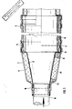
- two monoliths 4 are arranged axially one behind the other in the housing 2.
- the left half of the device is shown in the drawing, which must be thought of as a mirror image to the right.
- the housing 2 of the device shown in FIG. 1 consists of a central monolith receiving area 6, which - apart from a number of circumferential beads is cylindrical - has an essentially frustoconical transition area 8 to the right and left of it, and one each at the end of the respective transition area 8 essentially cylindrical connection area 10.
- the housing 2 consists of sheet steel and is preferably composed of two half-shells along an axial section plane.
- an inner shell 12 extends along the transition region 8 and at least for a part of the length of the receiving region 6 along this receiving region 6.
- the inner shell 12 begins a little behind the end of the connecting region 10 on the left and has there a small radial distance from the housing 2.
- the inner shell 12 runs in the Transition area 8 parallel to the housing 2 with a radial distance in the range of 2 to 15 mm.
- the inner shell 12 is bent outwards and from there lies against the housing 2 from the inside.
- the inner shell 12 is positively fixed at least in the left end region of the receiving region 6 by an inwardly pronounced bead 14 of the housing 2.
- the monolith 4 is cylindrical and consists of ceramic material, which is crossed in the axial direction by a plurality of channels which are vapor-coated with a catalytically active substance.
- a spacer mat 16 with a thickness of 2 to 15 mm is arranged in the receiving area 6, which ends somewhat to the left of the end faces of the monoliths 4.
- the distance between the inner shell 12 and the housing 2 is selected at the transition to the receiving area 6 so that the inner shell 12 slightly covers the end face of the monolith 4 at the edge.
- connection area 10 the end of an exhaust pipe 18 is inserted from the left, which projects into the end of the inner shell 12 with little play.
- the exhaust pipe 18 is welded to the outside of the connection area 10.
- the left end of the inner shell 12 thus projects into an annular gap between the end of the exhaust pipe 18 and the connection area 10, so that here on the one hand there is a possibility for the axial expansion and contraction of the inner shell 12 is given, but on the other hand a certain, labyrinth-like seal against propagation of the exhaust gas pulsations into the space between the housing 2 and the inner shell 12.
- a circumferential insulating mat 20 is provided between the housing 2 and the inner shell 12. This can be additionally protected on the left or left and right by a ring 22 made of material which swells under heat (FIG. 1 below) or by a support 24 made of heat-resistant fabric (FIG. 2 top) that surrounds the face.
- the ring 22 here is preferably made of pressed, heat-resistant wire knit or woven fabric, optionally interspersed or covered with heat-resistant, mineral fibers.
- the rings 22 can be designed as sealing rings, in particular in order to provide additional security against the monolith 4 flowing around.
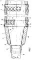
- the inner shell 12 extends over the entire length of the receiving area 6. This is not critical with regard to the thermal expansions, because the heat-insulating spacer mat 16 lies between and the heat conduction from the transition area 8 along the thin inner shell 12 is slight.
- the first part of the inner shell 12 ends a little behind the left end face of the monolith 4. In this end region of the first inner shell part, this ends in axially extending tongues 28, which are distributed along the circumference and formed by omega-shaped punched-outs 30.
- the tongues 28 lie on the outside of the monolith 4, possibly with the interposition of an elastic intermediate layer 32, and create a large-area but nevertheless elastic mounting of the monolith 4.
- the inner shell 12 is next to the described fastening point by means of welded holes 26 inwards again from the housing 2 led away so that the tongues 28 rest directly or indirectly on the outside of the monolith 4. This again results in a certain sealing effect.
- the spacer mat 16 is guided from the center of the monolith 4 to this diameter transition.
- central part 34 of the three-part inner shell 12 In the central area of the receiving area 6 there is a central part 34 of the three-part inner shell 12.
- the central part 34 is formed at both ends with tongues of the type described 28 and is fastened in the end area of the monolith 4 by a bead connection.
- a pure bead connection can be provided there.
- Both the insulating mat 20 and the spacer mat 16 are preferably made of ceramic fibers, which can be interspersed with expanded mica.
- the sheet of the inner shell 2 is more temperature-resistant and thinner than the sheet of the housing 2.
- the inner shell 12 or its parts can be made from half-shells, as described for the housing 2.
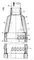
- the embodiment variants shown in FIG. 3 differ from the previously described exemplary embodiments essentially in that the inner shell 12 in the monolith receiving area 6 is not brought out to the outside of the housing 2, but also remains there at a distance from the housing 2.
- the connection there between the inner shell 12 and the monolith 4 is made in a manner similar to that in FIG. 2 with tongues 28 which are formed by omega-shaped punchings 30.
- the spacer mat 16 is guided approximately up to the end region of the monolith 4 on the left in FIG. 3, that is to say with its end region on the left in FIG. 3 between the end region on the right in FIG. 3 of the drawn section of the inner shell 12 and the housing 2.
- the spacer mat 16 is covered at least on its radially inner side and in the area where the drawn section of the inner shell 12 ends with a protective layer 24, preferably made of silicate fabric, see FIG. 3 above. 3 shows a modification in which the protective layer 24 is guided around the left end region of the spacer mat 16, that is to say the spacer mat 16 covers radially on the inside, on the front and radially on the outside.
- the middle section of the inner shell 12 which extends from the right end region of the left monolith 4 shown in the figures via an intermediate region between the two monoliths 4 to the left end region (not shown) of the one adjoining on the right in the figures, likewise does not drawn monolith 4 extends, too can be held in that it is held without direct contact with the housing 2 by an interposed insulating mat 20, which is preferably positively fixed in a corresponding bead of the housing 2. This is indicated in the drawing on the right in FIG. 3.
Landscapes
- Chemical & Material Sciences (AREA)
- Chemical Kinetics & Catalysis (AREA)
- Engineering & Computer Science (AREA)
- Health & Medical Sciences (AREA)
- Toxicology (AREA)
- Combustion & Propulsion (AREA)
- Mechanical Engineering (AREA)
- General Engineering & Computer Science (AREA)
- Exhaust Gas After Treatment (AREA)
Applications Claiming Priority (2)
| Application Number | Priority Date | Filing Date | Title |
|---|---|---|---|
| DE19873700070 DE3700070A1 (de) | 1987-01-02 | 1987-01-02 | Vorrichtung fuer die katalytische reinigung von fahrzeugmotor-abgasen |
| DE3700070 | 1987-01-02 |
Publications (2)
| Publication Number | Publication Date |
|---|---|
| EP0275565A1 true EP0275565A1 (fr) | 1988-07-27 |
| EP0275565B1 EP0275565B1 (fr) | 1991-06-26 |
Family
ID=6318409
Family Applications (1)
| Application Number | Title | Priority Date | Filing Date |
|---|---|---|---|
| EP87119403A Expired - Lifetime EP0275565B1 (fr) | 1987-01-02 | 1987-12-31 | Dispositif pour l'épuration catalytique des gaz d'échappement d'automobiles |
Country Status (6)
| Country | Link |
|---|---|
| US (1) | US4927608A (fr) |
| EP (1) | EP0275565B1 (fr) |
| DE (2) | DE3700070A1 (fr) |
| FR (1) | FR2609308A1 (fr) |
| IT (1) | IT1224432B (fr) |
| SE (1) | SE8704904L (fr) |
Cited By (2)
| Publication number | Priority date | Publication date | Assignee | Title |
|---|---|---|---|---|
| EP0415101A1 (fr) * | 1989-09-02 | 1991-03-06 | Leistritz Aktiengesellschaft | Système d'échappement, en particulier dispositif de purification de gaz d'échappement |
| DE4223648A1 (de) * | 1992-07-17 | 1994-01-20 | Zeuna Staerker Kg | Katalytische Abgasreinigungsvorrichtung |
Families Citing this family (45)
| Publication number | Priority date | Publication date | Assignee | Title |
|---|---|---|---|---|
| DE3820981A1 (de) * | 1988-06-22 | 1989-12-28 | Leistritz Ag | Abgasreinigungsvorrichtung mit dicht umhuellter lager- und isolationsmatte |
| DE3822944A1 (de) * | 1988-07-07 | 1990-01-11 | Leistritz Ag | Abgaskatalysator |
| DE3834403A1 (de) * | 1988-10-10 | 1990-04-12 | Zeuna Staerker Kg | Vorrichtung zur katalytischen reinigung von abgasen aus verbrennungsmotoren |
| DE3837503A1 (de) * | 1988-11-04 | 1990-05-10 | Gillet Heinrich Gmbh | Abgas-katalysator fuer kraftfahrzeuge |
| FR2646977B1 (fr) * | 1989-05-10 | 1994-07-29 | Thomson Csf | Procede et dispositif de transmission de l'information entre emetteurs-recepteurs radioelectriques d'un meme reseau fonctionnant en evasion de frequence |
| DE4024015A1 (de) * | 1990-07-28 | 1992-02-06 | Boysen Friedrich Gmbh Co Kg | Vorrichtung zur katalytischen reinigung bzw. zerlegung von heissen abgasen |
| DE4041856A1 (de) * | 1990-12-24 | 1992-06-25 | Behr Gmbh & Co | Vorrichtung zur katalytischen entgiftung von abgasen, vorzugsweise von verbrennungskraftmaschinen |
| DE4109626A1 (de) * | 1991-03-23 | 1992-09-24 | Eberspaecher J | Halterung eines traegerkoerpers in abgasanlagen von fahrzeugen |
| DE9202554U1 (de) * | 1992-02-27 | 1992-04-16 | Heinrich Gillet GmbH & Co KG, 6732 Edenkoben | Vorrichtung zum katalytischen Reinigen der Abgase von Verbrennungsmotoren |
| EP0678128B1 (fr) * | 1993-01-07 | 1996-09-25 | Minnesota Mining And Manufacturing Company | Mat non tisse souple |
| US6245301B1 (en) | 1993-08-20 | 2001-06-12 | 3M Innovative Properties Company | Catalytic converter and diesel particulate filter |
| US5882608A (en) * | 1996-06-18 | 1999-03-16 | Minnesota Mining And Manufacturing Company | Hybrid mounting system for pollution control devices |
| US6726884B1 (en) * | 1996-06-18 | 2004-04-27 | 3M Innovative Properties Company | Free-standing internally insulating liner |
| DE19711789C2 (de) * | 1997-03-21 | 2000-05-25 | Zeuna Staerker Kg | Kraftfahrzeug-Abgasreinigungsvorrichtung und Verfahren zu ihrer Herstellung |
| US6923942B1 (en) | 1997-05-09 | 2005-08-02 | 3M Innovative Properties Company | Compressible preform insulating liner |
| US6547208B2 (en) * | 2000-12-27 | 2003-04-15 | Delphi Technologies, Inc. | Motor mounting assembly |
| US20050002836A1 (en) * | 2001-04-13 | 2005-01-06 | Hardesty Jeffrey B. | Gas treatment device, and methods of making and using the same |
| FR2839533B1 (fr) * | 2002-05-07 | 2004-11-19 | Faurecia Sys Echappement | Dispositif nettoyable de depollution des gaz d'echappement d'un moteur |
| US7238327B2 (en) * | 2002-12-10 | 2007-07-03 | Automotive Components Holdings, Llc | Method of attaching internal heat shield in automotive catalytic converters |
| KR101148724B1 (ko) | 2003-01-22 | 2012-05-29 | 쓰리엠 이노베이티브 프로퍼티즈 컴파니 | 성형 3차원 절연체 |
| KR101058770B1 (ko) * | 2004-06-29 | 2011-08-24 | 유니프랙스 아이 엘엘씨 | 배기 가스 처리 장치 및 배기 가스 처리 장치의 제조 방법 |
| US20070081927A1 (en) * | 2005-10-07 | 2007-04-12 | Woon-Suck Baek | Catalytic converter cover |
| US7896943B2 (en) | 2008-02-07 | 2011-03-01 | Bgf Industries, Inc. | Frustum-shaped insulation for a pollution control device |
| EP2328674B1 (fr) * | 2008-08-29 | 2014-04-23 | Unifrax I LLC | Mat de montage avec protection de bord flexible et dispositif de traitement des gaz d échappement intégrant le mat de montage |
| DE102009043577B4 (de) * | 2008-10-01 | 2014-01-23 | Witzenmann Gmbh | Entkoppelelement mit einem Filterelement |
| KR101784013B1 (ko) | 2008-12-15 | 2017-10-10 | 유니프랙스 아이 엘엘씨 | 세라믹 허니콤 구조체의 스킨 코팅 |
| AU2009333811B2 (en) * | 2009-01-05 | 2013-08-22 | Unifrax I Llc | High strength biosoluble inorganic fiber insulation mat |
| CN102459834B (zh) * | 2009-04-17 | 2017-02-08 | 尤尼弗瑞克斯 I 有限责任公司 | 排气处理装置 |
| GB0906837D0 (en) | 2009-04-21 | 2009-06-03 | Saffil Automotive Ltd | Mats |
| WO2011019377A2 (fr) * | 2009-08-10 | 2011-02-17 | Unifrax I Llc | Préforme ou tapis de montage dont la masse surfacique est variable et dispositif de traitement des gaz déchappement |
| CN102686843B (zh) * | 2009-08-14 | 2015-04-01 | 尤尼弗瑞克斯I有限责任公司 | 多层基底支承体和排气处理装置 |
| US9174169B2 (en) | 2009-08-14 | 2015-11-03 | Unifrax I Llc | Mounting mat for exhaust gas treatment device |
| US8071040B2 (en) | 2009-09-23 | 2011-12-06 | Unifax I LLC | Low shear mounting mat for pollution control devices |
| CN102575552B (zh) * | 2009-09-24 | 2016-03-16 | 尤尼弗瑞克斯I有限责任公司 | 多层垫和废气处理装置 |
| ES2615496T3 (es) | 2009-12-01 | 2017-06-07 | Unifrax Emission Control Europe Ltd. | Esterilla de montaje |
| CN102753795B (zh) | 2009-12-17 | 2016-02-17 | 尤尼弗瑞克斯I有限责任公司 | 微球体在废气处理装置安装垫中的用途 |
| US20110150717A1 (en) * | 2009-12-17 | 2011-06-23 | Unifrax I Llc | Mounting mat for exhaust gas treatment device |
| CA2782413C (fr) * | 2009-12-17 | 2017-12-05 | Unifrax I Llc | Nappe de montage multicouche pour dispositifs antipollution |
| US8765069B2 (en) | 2010-08-12 | 2014-07-01 | Unifrax I Llc | Exhaust gas treatment device |
| EP2603676B1 (fr) | 2010-08-13 | 2016-03-23 | Unifrax I LLC | Matelas de fixation présentant une protection de bord flexible et dispositif de traitement des gaz d'échappement comprenant le matelas de fixation |
| US9924564B2 (en) | 2010-11-11 | 2018-03-20 | Unifrax I Llc | Heated mat and exhaust gas treatment device |
| EP2638261A4 (fr) | 2010-11-11 | 2014-08-06 | Unifrax I Llc | Mat de support et dispositif de traitement des gaz d'échappement |
| SE536327C2 (sv) | 2011-11-22 | 2013-08-20 | Scania Cv Ab | Arrangemang för montering av en avgasrenande enhet i en avgaspassage |
| DE102014006761A1 (de) * | 2013-06-21 | 2014-12-24 | Modine Manufacturing Company | Abgaskühler |
| KR20170118679A (ko) | 2015-02-24 | 2017-10-25 | 유니프랙스 아이 엘엘씨 | 내고온성 절연 매트 |
Citations (10)
| Publication number | Priority date | Publication date | Assignee | Title |
|---|---|---|---|---|
| DE2211522A1 (de) * | 1972-03-10 | 1973-09-13 | Volkswagenwerk Ag | Vorrichtung zur katalytischen abgasreinigung, insbesondere fuer kraftfahrzeugmotoren |
| FR2200886A5 (fr) * | 1972-09-23 | 1974-04-19 | Daimler Benz Ag | |
| DE2301646A1 (de) * | 1973-01-13 | 1974-08-01 | Pforzheim Metallschlauch | Katalysatortopf fuer abgasleitungen |
| DE2364425A1 (de) * | 1973-12-22 | 1975-07-10 | Boysen Friedrich Kg | Katalysator, insbesondere fuer auspuffund entgiftungsanlagen |
| US4043761A (en) * | 1975-03-03 | 1977-08-23 | J. Eberspacher | Catalytic converter having resilient monolith-mounting means |
| US4155980A (en) * | 1976-06-19 | 1979-05-22 | Zeuna-Starker Kg | Apparatus for catalytic purifying the effluent gases of internal combustion engines |
| DE3402916A1 (de) * | 1984-01-28 | 1985-08-08 | Daimler-Benz Ag, 7000 Stuttgart | Katalysatorgehaeuse fuer kraftfahrzeuge |
| DE3433938A1 (de) * | 1984-09-15 | 1985-10-24 | Bayerische Motoren Werke AG, 8000 München | Abgaskonverter fuer brennkraftmaschinen |
| EP0176722A1 (fr) * | 1984-09-01 | 1986-04-09 | Leistritz Aktiengesellschaft | Dispositif de désintoxication catalytique des gaz d'échappement |
| EP0193072A1 (fr) * | 1985-02-22 | 1986-09-03 | Leistritz Aktiengesellschaft | Dispositif d'épuration catalytique des gaz d'échappement |
Family Cites Families (15)
| Publication number | Priority date | Publication date | Assignee | Title |
|---|---|---|---|---|
| US4344922A (en) * | 1972-03-21 | 1982-08-17 | Zeuna-Staerker Kg | Catalyzer for detoxifying exhaust gases from internal combustion |
| US4004888A (en) * | 1972-04-07 | 1977-01-25 | Kali-Chemie Aktiengesellschaft | Exhaust gas cleaning arrangement with a resiliently supported monolithic ceramic catalyzer |
| JPS5148529B2 (fr) * | 1972-05-13 | 1976-12-21 | ||
| DE2243251B2 (de) * | 1972-09-02 | 1976-01-02 | Paul Gillet Gmbh, 6732 Edenkoben | Vorrichtung zur Reinigung der Abgase von Brennkraftmaschinen |
| US3817714A (en) * | 1972-10-10 | 1974-06-18 | Corning Glass Works | Catalytic converter |
| US4004887A (en) * | 1973-03-16 | 1977-01-25 | Tenneco Inc. | Catalytic converter having a resilient thermal-variation compensating monolith-mounting arrangement |
| US3978567A (en) * | 1973-03-19 | 1976-09-07 | Chrysler Corporation | Method of making a catalytic reactor for automobile |
| DE2407990A1 (de) * | 1974-02-20 | 1975-08-28 | Eberspaecher J | Vorrichtung zur katalytischen reinigung der abgase von brennkraftmaschinen |
| DE2458994A1 (de) * | 1974-12-13 | 1976-06-16 | Eberspaecher J | Anordnung zur katalytischen reinigung von abgasen |
| DE2824567A1 (de) * | 1978-06-05 | 1979-12-06 | Hoechst Ag | Abgaskonverter fuer brennkraftmaschinen |
| JPS6027770Y2 (ja) * | 1980-03-07 | 1985-08-22 | 日産自動車株式会社 | 触媒式排気後処理装置のガスシ−ル保護構造 |
| DE3509790A1 (de) * | 1985-03-19 | 1986-10-09 | LEISTRITZ Maschinenfabrik GmbH, 8500 Nürnberg | Abgasreinigungsvorrichtung fuer kraftfahrzeuge |
| DE3506219A1 (de) * | 1985-02-22 | 1986-09-04 | LEISTRITZ Maschinenfabrik GmbH, 8500 Nürnberg | Katalytische abgasentgiftungseinrichtung |
| DE3524775C1 (de) * | 1985-07-11 | 1986-09-04 | Daimler-Benz Ag, 7000 Stuttgart | In einem metallenen Gehaeuse angeordneter monolithischer Abgaskatalysator |
| US4667386A (en) * | 1985-08-23 | 1987-05-26 | Honda Giken Kogyo Kabushiki Kaisha | Method and apparatus for assembling an insert assembly for a catalytic converter |
-
1987
- 1987-01-02 DE DE19873700070 patent/DE3700070A1/de not_active Withdrawn
- 1987-12-08 SE SE8704904A patent/SE8704904L/xx not_active Application Discontinuation
- 1987-12-29 IT IT23257/87A patent/IT1224432B/it active
- 1987-12-29 FR FR8718517A patent/FR2609308A1/fr not_active Withdrawn
- 1987-12-31 DE DE8787119403T patent/DE3771058D1/de not_active Expired - Lifetime
- 1987-12-31 US US07/139,904 patent/US4927608A/en not_active Expired - Fee Related
- 1987-12-31 EP EP87119403A patent/EP0275565B1/fr not_active Expired - Lifetime
Patent Citations (10)
| Publication number | Priority date | Publication date | Assignee | Title |
|---|---|---|---|---|
| DE2211522A1 (de) * | 1972-03-10 | 1973-09-13 | Volkswagenwerk Ag | Vorrichtung zur katalytischen abgasreinigung, insbesondere fuer kraftfahrzeugmotoren |
| FR2200886A5 (fr) * | 1972-09-23 | 1974-04-19 | Daimler Benz Ag | |
| DE2301646A1 (de) * | 1973-01-13 | 1974-08-01 | Pforzheim Metallschlauch | Katalysatortopf fuer abgasleitungen |
| DE2364425A1 (de) * | 1973-12-22 | 1975-07-10 | Boysen Friedrich Kg | Katalysator, insbesondere fuer auspuffund entgiftungsanlagen |
| US4043761A (en) * | 1975-03-03 | 1977-08-23 | J. Eberspacher | Catalytic converter having resilient monolith-mounting means |
| US4155980A (en) * | 1976-06-19 | 1979-05-22 | Zeuna-Starker Kg | Apparatus for catalytic purifying the effluent gases of internal combustion engines |
| DE3402916A1 (de) * | 1984-01-28 | 1985-08-08 | Daimler-Benz Ag, 7000 Stuttgart | Katalysatorgehaeuse fuer kraftfahrzeuge |
| EP0176722A1 (fr) * | 1984-09-01 | 1986-04-09 | Leistritz Aktiengesellschaft | Dispositif de désintoxication catalytique des gaz d'échappement |
| DE3433938A1 (de) * | 1984-09-15 | 1985-10-24 | Bayerische Motoren Werke AG, 8000 München | Abgaskonverter fuer brennkraftmaschinen |
| EP0193072A1 (fr) * | 1985-02-22 | 1986-09-03 | Leistritz Aktiengesellschaft | Dispositif d'épuration catalytique des gaz d'échappement |
Cited By (2)
| Publication number | Priority date | Publication date | Assignee | Title |
|---|---|---|---|---|
| EP0415101A1 (fr) * | 1989-09-02 | 1991-03-06 | Leistritz Aktiengesellschaft | Système d'échappement, en particulier dispositif de purification de gaz d'échappement |
| DE4223648A1 (de) * | 1992-07-17 | 1994-01-20 | Zeuna Staerker Kg | Katalytische Abgasreinigungsvorrichtung |
Also Published As
| Publication number | Publication date |
|---|---|
| IT8723257A0 (it) | 1987-12-29 |
| SE8704904D0 (sv) | 1987-12-08 |
| FR2609308A1 (fr) | 1988-07-08 |
| IT1224432B (it) | 1990-10-04 |
| US4927608A (en) | 1990-05-22 |
| DE3771058D1 (de) | 1991-08-01 |
| SE8704904L (sv) | 1988-07-03 |
| EP0275565B1 (fr) | 1991-06-26 |
| DE3700070A1 (de) | 1988-07-14 |
Similar Documents
| Publication | Publication Date | Title |
|---|---|---|
| EP0275565B1 (fr) | Dispositif pour l'épuration catalytique des gaz d'échappement d'automobiles | |
| DE3007868C2 (fr) | ||
| EP0683851B1 (fr) | Element metallique alveole maintenu dans un tube de protection interieur et exterieur, notamment element-support de catalyseur | |
| EP0387422B1 (fr) | Appareil pour la purification catalytique etc. des gaz d'échappement des moteurs à combustion interne ayant deux corps de traitement des gaz et un anneau de protection entre eux | |
| EP0582985A1 (fr) | Collecteur d'échappement | |
| EP0537603B1 (fr) | Tuyau à paroi double, isolé par de l'air, pour des installations d'échappement de véhicules | |
| EP0435956A1 (fr) | Catalyseur a systeme d'enveloppe double. | |
| EP0503580B1 (fr) | Conduit d'échappement isolé par une couche d'air | |
| DE3007867A1 (de) | Katalytischer konverter fuer brennkraftmaschinenabgase | |
| DE69520532T2 (de) | Vorrichtung zur Reinigung von Motorabgasen | |
| DE102022116755A1 (de) | Heizeinrichtung zum Beheizen eines Gasstroms | |
| EP4198274A1 (fr) | Dispositif de chauffage pour chauffer un courant de gaz | |
| WO2002023021A1 (fr) | Corps en nid d'abeilles a tube interieur de protection fendu et raccourci | |
| EP0193072B1 (fr) | Dispositif d'épuration catalytique des gaz d'échappement | |
| DE3926072C2 (de) | Katalysator zur Abgasreinigung mit elastischen Elementen zum Ausgleich von Längsdehnungen | |
| EP0561019B1 (fr) | Dispositif pour le positionnement d'un boîtier intérieur dans le boîtier d'une installation d'échappement pour véhicules | |
| EP0472009B1 (fr) | Dispositif de purification de gaz d'échappement avec deux corps de traitement de gaz l'un après l'autre | |
| EP1422396B1 (fr) | catalyseur à lits multiples | |
| DE10114785A1 (de) | Abgasreinigungseinrichtung | |
| DE4009945C2 (de) | Abgaskonverter für Brennkraftmaschinen | |
| DE69804564T2 (de) | Heizvorrichtung | |
| DE3506219C2 (fr) | ||
| DE3922667A1 (de) | Vorrichtung zur katalytischen entgiftung oder dgl. von verbrennungsmotor-abgasen mit doppelwandigem gehaeuse | |
| DE102022111864B4 (de) | Heizvorrichtung | |
| DE3821397A1 (de) | Vorrichtung zur katalytischen reinigung von verbrennungsmotor-abgasen |
Legal Events
| Date | Code | Title | Description |
|---|---|---|---|
| PUAI | Public reference made under article 153(3) epc to a published international application that has entered the european phase |
Free format text: ORIGINAL CODE: 0009012 |
|
| 17P | Request for examination filed |
Effective date: 19880119 |
|
| AK | Designated contracting states |
Kind code of ref document: A1 Designated state(s): DE FR IT SE |
|
| 17Q | First examination report despatched |
Effective date: 19881216 |
|
| GRAA | (expected) grant |
Free format text: ORIGINAL CODE: 0009210 |
|
| AK | Designated contracting states |
Kind code of ref document: B1 Designated state(s): DE FR IT SE |
|
| ITF | It: translation for a ep patent filed | ||
| REF | Corresponds to: |
Ref document number: 3771058 Country of ref document: DE Date of ref document: 19910801 |
|
| ET | Fr: translation filed | ||
| PGFP | Annual fee paid to national office [announced via postgrant information from national office to epo] |
Ref country code: SE Payment date: 19911113 Year of fee payment: 5 |
|
| PGFP | Annual fee paid to national office [announced via postgrant information from national office to epo] |
Ref country code: FR Payment date: 19911211 Year of fee payment: 5 |
|
| PLBE | No opposition filed within time limit |
Free format text: ORIGINAL CODE: 0009261 |
|
| STAA | Information on the status of an ep patent application or granted ep patent |
Free format text: STATUS: NO OPPOSITION FILED WITHIN TIME LIMIT |
|
| 26N | No opposition filed | ||
| PG25 | Lapsed in a contracting state [announced via postgrant information from national office to epo] |
Ref country code: SE Effective date: 19930101 |
|
| PG25 | Lapsed in a contracting state [announced via postgrant information from national office to epo] |
Ref country code: FR Effective date: 19930831 |
|
| REG | Reference to a national code |
Ref country code: FR Ref legal event code: ST |
|
| EUG | Se: european patent has lapsed |
Ref document number: 87119403.1 Effective date: 19930810 |
|
| PGFP | Annual fee paid to national office [announced via postgrant information from national office to epo] |
Ref country code: DE Payment date: 19970203 Year of fee payment: 10 |
|
| PG25 | Lapsed in a contracting state [announced via postgrant information from national office to epo] |
Ref country code: DE Free format text: LAPSE BECAUSE OF NON-PAYMENT OF DUE FEES Effective date: 19980901 |
|
| PG25 | Lapsed in a contracting state [announced via postgrant information from national office to epo] |
Ref country code: IT Free format text: LAPSE BECAUSE OF NON-PAYMENT OF DUE FEES;WARNING: LAPSES OF ITALIAN PATENTS WITH EFFECTIVE DATE BEFORE 2007 MAY HAVE OCCURRED AT ANY TIME BEFORE 2007. THE CORRECT EFFECTIVE DATE MAY BE DIFFERENT FROM THE ONE RECORDED. Effective date: 20051231 |