EP0415101A1 - Système d'échappement, en particulier dispositif de purification de gaz d'échappement - Google Patents
Système d'échappement, en particulier dispositif de purification de gaz d'échappement Download PDFInfo
- Publication number
- EP0415101A1 EP0415101A1 EP90114642A EP90114642A EP0415101A1 EP 0415101 A1 EP0415101 A1 EP 0415101A1 EP 90114642 A EP90114642 A EP 90114642A EP 90114642 A EP90114642 A EP 90114642A EP 0415101 A1 EP0415101 A1 EP 0415101A1
- Authority
- EP
- European Patent Office
- Prior art keywords
- mat
- shielding
- exhaust gas
- rings
- shell
- Prior art date
- Legal status (The legal status is an assumption and is not a legal conclusion. Google has not performed a legal analysis and makes no representation as to the accuracy of the status listed.)
- Granted
Links
Images

Classifications
-
- F—MECHANICAL ENGINEERING; LIGHTING; HEATING; WEAPONS; BLASTING
- F01—MACHINES OR ENGINES IN GENERAL; ENGINE PLANTS IN GENERAL; STEAM ENGINES
- F01N—GAS-FLOW SILENCERS OR EXHAUST APPARATUS FOR MACHINES OR ENGINES IN GENERAL; GAS-FLOW SILENCERS OR EXHAUST APPARATUS FOR INTERNAL-COMBUSTION ENGINES
- F01N13/00—Exhaust or silencing apparatus characterised by constructional features
- F01N13/08—Other arrangements or adaptations of exhaust conduits
- F01N13/10—Other arrangements or adaptations of exhaust conduits of exhaust manifolds
- F01N13/102—Other arrangements or adaptations of exhaust conduits of exhaust manifolds having thermal insulation
-
- F—MECHANICAL ENGINEERING; LIGHTING; HEATING; WEAPONS; BLASTING
- F01—MACHINES OR ENGINES IN GENERAL; ENGINE PLANTS IN GENERAL; STEAM ENGINES
- F01N—GAS-FLOW SILENCERS OR EXHAUST APPARATUS FOR MACHINES OR ENGINES IN GENERAL; GAS-FLOW SILENCERS OR EXHAUST APPARATUS FOR INTERNAL-COMBUSTION ENGINES
- F01N13/00—Exhaust or silencing apparatus characterised by constructional features
- F01N13/009—Exhaust or silencing apparatus characterised by constructional features having two or more separate purifying devices arranged in series
- F01N13/0097—Exhaust or silencing apparatus characterised by constructional features having two or more separate purifying devices arranged in series the purifying devices are arranged in a single housing
-
- F—MECHANICAL ENGINEERING; LIGHTING; HEATING; WEAPONS; BLASTING
- F01—MACHINES OR ENGINES IN GENERAL; ENGINE PLANTS IN GENERAL; STEAM ENGINES
- F01N—GAS-FLOW SILENCERS OR EXHAUST APPARATUS FOR MACHINES OR ENGINES IN GENERAL; GAS-FLOW SILENCERS OR EXHAUST APPARATUS FOR INTERNAL-COMBUSTION ENGINES
- F01N13/00—Exhaust or silencing apparatus characterised by constructional features
- F01N13/14—Exhaust or silencing apparatus characterised by constructional features having thermal insulation
- F01N13/141—Double-walled exhaust pipes or housings
-
- F—MECHANICAL ENGINEERING; LIGHTING; HEATING; WEAPONS; BLASTING
- F01—MACHINES OR ENGINES IN GENERAL; ENGINE PLANTS IN GENERAL; STEAM ENGINES
- F01N—GAS-FLOW SILENCERS OR EXHAUST APPARATUS FOR MACHINES OR ENGINES IN GENERAL; GAS-FLOW SILENCERS OR EXHAUST APPARATUS FOR INTERNAL-COMBUSTION ENGINES
- F01N3/00—Exhaust or silencing apparatus having means for purifying, rendering innocuous, or otherwise treating exhaust
- F01N3/08—Exhaust or silencing apparatus having means for purifying, rendering innocuous, or otherwise treating exhaust for rendering innocuous
- F01N3/10—Exhaust or silencing apparatus having means for purifying, rendering innocuous, or otherwise treating exhaust for rendering innocuous by thermal or catalytic conversion of noxious components of exhaust
- F01N3/24—Exhaust or silencing apparatus having means for purifying, rendering innocuous, or otherwise treating exhaust for rendering innocuous by thermal or catalytic conversion of noxious components of exhaust characterised by constructional aspects of converting apparatus
- F01N3/28—Construction of catalytic reactors
- F01N3/2839—Arrangements for mounting catalyst support in housing, e.g. with means for compensating thermal expansion or vibration
- F01N3/2853—Arrangements for mounting catalyst support in housing, e.g. with means for compensating thermal expansion or vibration using mats or gaskets between catalyst body and housing
- F01N3/2857—Arrangements for mounting catalyst support in housing, e.g. with means for compensating thermal expansion or vibration using mats or gaskets between catalyst body and housing the mats or gaskets being at least partially made of intumescent material, e.g. unexpanded vermiculite
-
- F—MECHANICAL ENGINEERING; LIGHTING; HEATING; WEAPONS; BLASTING
- F01—MACHINES OR ENGINES IN GENERAL; ENGINE PLANTS IN GENERAL; STEAM ENGINES
- F01N—GAS-FLOW SILENCERS OR EXHAUST APPARATUS FOR MACHINES OR ENGINES IN GENERAL; GAS-FLOW SILENCERS OR EXHAUST APPARATUS FOR INTERNAL-COMBUSTION ENGINES
- F01N2310/00—Selection of sound absorbing or insulating material
- F01N2310/02—Mineral wool, e.g. glass wool, rock wool, asbestos or the like
-
- F—MECHANICAL ENGINEERING; LIGHTING; HEATING; WEAPONS; BLASTING
- F01—MACHINES OR ENGINES IN GENERAL; ENGINE PLANTS IN GENERAL; STEAM ENGINES
- F01N—GAS-FLOW SILENCERS OR EXHAUST APPARATUS FOR MACHINES OR ENGINES IN GENERAL; GAS-FLOW SILENCERS OR EXHAUST APPARATUS FOR INTERNAL-COMBUSTION ENGINES
- F01N2350/00—Arrangements for fitting catalyst support or particle filter element in the housing
- F01N2350/02—Fitting ceramic monoliths in a metallic housing
-
- F—MECHANICAL ENGINEERING; LIGHTING; HEATING; WEAPONS; BLASTING
- F01—MACHINES OR ENGINES IN GENERAL; ENGINE PLANTS IN GENERAL; STEAM ENGINES
- F01N—GAS-FLOW SILENCERS OR EXHAUST APPARATUS FOR MACHINES OR ENGINES IN GENERAL; GAS-FLOW SILENCERS OR EXHAUST APPARATUS FOR INTERNAL-COMBUSTION ENGINES
- F01N2470/00—Structure or shape of exhaust gas passages, pipes or tubes
- F01N2470/10—Tubes having non-circular cross section
Definitions
- the invention relates to an exhaust device with a double-shell housing, the inner shell being mounted at least in sections via an elastic bearing mat, in particular mineral fiber mat in the outer shell, in particular an exhaust gas cleaning device with an outer housing consisting of two half-shells, in which via an elastic bearing mat, in particular a so-called swelling mat, at least one honeycomb-structured carrier body and inner and outer shielding funnels and, if necessary, shielding rings are mounted between successive carrier bodies.
- the invention is therefore based on the object of designing an exhaust gas device of the type mentioned in such a way that the problems with axial and radial expansion differences are solved with a simple structure, and moreover with a favorable transition to any ceramic parts, without the occurrence of stress peaks and the risk of wrinkles can be.
- the shielding funnels and rings are formed from a close-meshed, sliding elastic wire mesh mat and are held fixed on both ends.
- the configuration according to the invention can solve a number of special problems in one.
- a wire mesh mat - mesh fabrics with a mesh width of ⁇ 0.5 mm are particularly suitable - can be processed very easily in press or deep-drawing molds, so that even very complicated shell structures can be produced.
- shielding parts made of a wire mesh mat, both in the longitudinal direction and radially and in the transverse direction are very large Provide elasticity so that the expansion differences mentioned at the beginning can be easily absorbed in the wire mesh in both the axial direction and in the radial direction.
- the special properties of a wire mesh mat also evidently prevent any risk of creasing at different expansions, for example of the shielding funnel produced from such a wire mesh mat and of the ceramic support body which is subsequently clamped around.
- the porosity of a shielding funnel made of a wire mesh mat does not interfere in any way with the dense design of a shielding funnel drawn from sheet metal, since with a sufficiently small mesh size, sufficient elasticity of the inner shielding component produced therefrom is still guaranteed on the one hand and on the other hand due to the occurring mesh opening neither damage to the mineral fiber mat can take place, which in practice is anyway more heat-resistant than metal, but on the other hand also blowing out or otherwise falling out of parts from the mineral fiber mat can be reliably prevented.
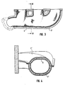
- the shielding funnel 7 which consists of a wire mesh mat, is resiliently stretched onto the end of the carrier body 4, an additional holding effect also being provided by the pressure of the surrounding mineral fiber mat 5.
- the inner shielding cylinder can not only be placed very easily around complicated inner structures, as must be the case with the complex-shaped carrier body 4 (FIG. 2), but there can be neither thermally induced stress peaks nor warping or wrinkling Shielding funnels or shielding rings, neither in the radial nor in the axial direction.
- 3 and 4 is shown using an insulated double shell manifold with a metallic outer housing 1 'and an inner housing 9, as the inventive design of the inner housing from a wire mesh mat in a very simple and effective form can also be used in other types of exhaust devices, to avoid the otherwise usual complicated sliding seats in the area of the inner housing and / or outer housing.
- a mineral fiber mat 5 'between the outer housing 1' and the wire mesh mat-shaped inner housing 9 provided, because of the complicated structure, the mineral fiber mat 5 'is preferably composed of divided blanks, which preferably abut against one another with their abutting edges.
- the invention is not restricted to the exemplary embodiments shown.
- This design can namely be provided in the area of the shielding funnels or rings that the elastic bearing mat is completely eliminated over large sections, which in turn has the advantage that no high compressive forces of this elastic fiber mat have to be absorbed by the wire mesh shielding funnels and shielding rings .
- the production from the wire mesh mat instead of the usual metal sheets has the advantage that, for example, damage to the monolith is eliminated by the encompassing edge of the shielding funnel or shielding ring. Due to the thermally insulating intermediate layer, excessive thermal heating of the outer shell is avoided even without pulling the bearing mat over the area of the rings and shielding funnels, and on the other hand - in particular if the thermally insulating intermediate layer as paper, film or the like. is made of thermally resistant material - prevents hot exhaust gases from getting into the space between the inner shell and the outer shell, so that they are neither there heating or blowing out the elastic mineral fiber mat present in the area of the monolith at the latest.
Landscapes
- Engineering & Computer Science (AREA)
- Chemical & Material Sciences (AREA)
- Chemical Kinetics & Catalysis (AREA)
- Combustion & Propulsion (AREA)
- Mechanical Engineering (AREA)
- General Engineering & Computer Science (AREA)
- Health & Medical Sciences (AREA)
- Toxicology (AREA)
- Exhaust Gas After Treatment (AREA)
- Filtering Of Dispersed Particles In Gases (AREA)
Applications Claiming Priority (2)
| Application Number | Priority Date | Filing Date | Title |
|---|---|---|---|
| DE3929205 | 1989-09-02 | ||
| DE3929205A DE3929205A1 (de) | 1989-09-02 | 1989-09-02 | Abgasvorrichtung, insbes. abgasreinigungsvorrichtung |
Publications (2)
| Publication Number | Publication Date |
|---|---|
| EP0415101A1 true EP0415101A1 (fr) | 1991-03-06 |
| EP0415101B1 EP0415101B1 (fr) | 1993-09-22 |
Family
ID=6388521
Family Applications (1)
| Application Number | Title | Priority Date | Filing Date |
|---|---|---|---|
| EP90114642A Expired - Lifetime EP0415101B1 (fr) | 1989-09-02 | 1990-07-31 | Système d'échappement, en particulier dispositif de purification de gaz d'échappement |
Country Status (3)
| Country | Link |
|---|---|
| EP (1) | EP0415101B1 (fr) |
| DE (2) | DE3929205A1 (fr) |
| ES (1) | ES2044341T3 (fr) |
Cited By (8)
| Publication number | Priority date | Publication date | Assignee | Title |
|---|---|---|---|---|
| EP0472009A1 (fr) * | 1990-08-22 | 1992-02-26 | Firma J. Eberspächer | Dispositif de purification de gaz d'échappement avec deux corps de traitement de gaz l'un après l'autre |
| EP0603754A1 (fr) * | 1992-12-22 | 1994-06-29 | LEISTRITZ AG & CO. Abgastechnik | Dispositif pour réduire les émissions d'échappement, en particulier pour véhicules à moteur |
| EP0719912A1 (fr) * | 1994-12-30 | 1996-07-03 | Firma J. Eberspächer | Dispositif de traitement de gaz d'échappement d'un moteur à combustion interne |
| FR2751376A1 (fr) * | 1996-07-17 | 1998-01-23 | Daimler Benz Ag | Tubulure coudee de gaz d'echappement pour le guidage des gaz d'echappement d'un moteur a combustion interne |
| EP1308607A3 (fr) * | 2001-11-02 | 2004-06-09 | Delphi Technologies, Inc. | Extrémités coniques pour dispositifs d'émission de gaz d'échappement et procédé de fabrication |
| FR3084109A1 (fr) * | 2018-07-23 | 2020-01-24 | Renault S.A.S. | Dispositif d’isolation thermique a l’echappement de moteur thermique |
| DE102019104940A1 (de) * | 2019-02-27 | 2020-08-27 | Eberspächer Exhaust Technology GmbH & Co. KG | Abgaskonverter-Gehäusestruktur |
| CN115585037A (zh) * | 2022-09-27 | 2023-01-10 | 九江学院 | 一种尾气捕集结构 |
Families Citing this family (6)
| Publication number | Priority date | Publication date | Assignee | Title |
|---|---|---|---|---|
| DE4201426C2 (de) * | 1992-01-21 | 1994-03-31 | Leistritz Abgastech | Abgasreinigungsvorrichtung |
| DE4323791C2 (de) * | 1993-07-15 | 1997-03-20 | Daimler Benz Ag | Abgasnachbehandlungseinrichtung zum katalytischen Reinigen der Abgase von Brennkraftmaschinen |
| DE10018805A1 (de) | 2000-04-15 | 2001-11-29 | Volkswagen Ag | Verfahren und Vorrichtung zur Herstellung eines Katalysators mit einem einen polygonen Querschnitt aufweisenden Monolithen |
| DE102009016266B4 (de) | 2009-04-03 | 2014-08-21 | Audi Ag | Abgaskrümmer |
| DE102009037520A1 (de) * | 2009-08-17 | 2011-04-21 | Poroson Gmbh | Abgaskrümmer |
| US9790836B2 (en) | 2012-11-20 | 2017-10-17 | Tenneco Automotive Operating Company, Inc. | Loose-fill insulation exhaust gas treatment device and methods of manufacturing |
Citations (3)
| Publication number | Priority date | Publication date | Assignee | Title |
|---|---|---|---|---|
| EP0193072A1 (fr) * | 1985-02-22 | 1986-09-03 | Leistritz Aktiengesellschaft | Dispositif d'épuration catalytique des gaz d'échappement |
| EP0275565A1 (fr) * | 1987-01-02 | 1988-07-27 | Firma J. Eberspächer | Dispositif pour l'épuration catalytique des gaz d'échappement d'automobiles |
| DE3821397A1 (de) * | 1988-06-24 | 1989-12-28 | Eberspaecher J | Vorrichtung zur katalytischen reinigung von verbrennungsmotor-abgasen |
Family Cites Families (5)
| Publication number | Priority date | Publication date | Assignee | Title |
|---|---|---|---|---|
| DE2222663C3 (de) * | 1972-05-09 | 1975-03-06 | Zeuna-Staerker Kg, 8900 Augsburg | Verfahren zur Herstellung einer Vorrichtung zur Reinigung der Abgase von Brennkraftmaschinen |
| JPS54160558A (en) * | 1978-05-19 | 1979-12-19 | Chuo Hatsujo Kk | Forming metal wire cushion body and product thereof |
| DE3509790A1 (de) * | 1985-03-19 | 1986-10-09 | LEISTRITZ Maschinenfabrik GmbH, 8500 Nürnberg | Abgasreinigungsvorrichtung fuer kraftfahrzeuge |
| DE3710299A1 (de) * | 1987-03-28 | 1988-10-13 | Eberspaecher J | Anordnung zur halterung eines katalysators in einem gehaeuse im abgassystem eines mit fluessigem brennstoff betriebenen motors |
| DE3729994A1 (de) * | 1987-09-08 | 1989-03-16 | Bischoff Erhardt Gmbh Co Kg | Vorrichtung zum katalytischen reinigen von abgasen |
-
1989
- 1989-09-02 DE DE3929205A patent/DE3929205A1/de active Granted
-
1990
- 1990-07-31 DE DE90114642T patent/DE59002823D1/de not_active Expired - Fee Related
- 1990-07-31 EP EP90114642A patent/EP0415101B1/fr not_active Expired - Lifetime
- 1990-07-31 ES ES90114642T patent/ES2044341T3/es not_active Expired - Lifetime
Patent Citations (3)
| Publication number | Priority date | Publication date | Assignee | Title |
|---|---|---|---|---|
| EP0193072A1 (fr) * | 1985-02-22 | 1986-09-03 | Leistritz Aktiengesellschaft | Dispositif d'épuration catalytique des gaz d'échappement |
| EP0275565A1 (fr) * | 1987-01-02 | 1988-07-27 | Firma J. Eberspächer | Dispositif pour l'épuration catalytique des gaz d'échappement d'automobiles |
| DE3821397A1 (de) * | 1988-06-24 | 1989-12-28 | Eberspaecher J | Vorrichtung zur katalytischen reinigung von verbrennungsmotor-abgasen |
Non-Patent Citations (1)
| Title |
|---|
| PATENT ABSTRACTS OF JAPAN vol. 12, no. 195 (M-705)(3042) 07 Juni 1988, & JP-A-63 001708 (YUTAKA) 06 Januar 1988, * |
Cited By (10)
| Publication number | Priority date | Publication date | Assignee | Title |
|---|---|---|---|---|
| EP0472009A1 (fr) * | 1990-08-22 | 1992-02-26 | Firma J. Eberspächer | Dispositif de purification de gaz d'échappement avec deux corps de traitement de gaz l'un après l'autre |
| EP0603754A1 (fr) * | 1992-12-22 | 1994-06-29 | LEISTRITZ AG & CO. Abgastechnik | Dispositif pour réduire les émissions d'échappement, en particulier pour véhicules à moteur |
| EP0719912A1 (fr) * | 1994-12-30 | 1996-07-03 | Firma J. Eberspächer | Dispositif de traitement de gaz d'échappement d'un moteur à combustion interne |
| FR2751376A1 (fr) * | 1996-07-17 | 1998-01-23 | Daimler Benz Ag | Tubulure coudee de gaz d'echappement pour le guidage des gaz d'echappement d'un moteur a combustion interne |
| EP1308607A3 (fr) * | 2001-11-02 | 2004-06-09 | Delphi Technologies, Inc. | Extrémités coniques pour dispositifs d'émission de gaz d'échappement et procédé de fabrication |
| FR3084109A1 (fr) * | 2018-07-23 | 2020-01-24 | Renault S.A.S. | Dispositif d’isolation thermique a l’echappement de moteur thermique |
| WO2020020828A1 (fr) * | 2018-07-23 | 2020-01-30 | Renault S.A.S | Dispositif d'isolation thermique a l'echappement de moteur thermique |
| CN112469892A (zh) * | 2018-07-23 | 2021-03-09 | 雷诺股份公司 | 用于热力发动机的排气的热绝缘装置 |
| DE102019104940A1 (de) * | 2019-02-27 | 2020-08-27 | Eberspächer Exhaust Technology GmbH & Co. KG | Abgaskonverter-Gehäusestruktur |
| CN115585037A (zh) * | 2022-09-27 | 2023-01-10 | 九江学院 | 一种尾气捕集结构 |
Also Published As
| Publication number | Publication date |
|---|---|
| DE3929205C2 (fr) | 1992-01-23 |
| ES2044341T3 (es) | 1994-01-01 |
| DE59002823D1 (de) | 1993-10-28 |
| DE3929205A1 (de) | 1991-03-21 |
| EP0415101B1 (fr) | 1993-09-22 |
Similar Documents
| Publication | Publication Date | Title |
|---|---|---|
| EP0415101B1 (fr) | Système d'échappement, en particulier dispositif de purification de gaz d'échappement | |
| EP0176722B1 (fr) | Dispositif de désintoxication catalytique des gaz d'échappement | |
| DE3007868C2 (fr) | ||
| EP0275565B1 (fr) | Dispositif pour l'épuration catalytique des gaz d'échappement d'automobiles | |
| EP0582985A1 (fr) | Collecteur d'échappement | |
| EP1612328B1 (fr) | Appareil de séchage en continu d'une bande fibreuse | |
| DE3927895C1 (fr) | ||
| EP0193072B1 (fr) | Dispositif d'épuration catalytique des gaz d'échappement | |
| DE3514150C1 (de) | Katalytische Abgasentgiftungsvorrichtung mit stabilisierter Federmatte | |
| DE3326260A1 (de) | Auspuffleitung | |
| EP0472009B1 (fr) | Dispositif de purification de gaz d'échappement avec deux corps de traitement de gaz l'un après l'autre | |
| DE3509790A1 (de) | Abgasreinigungsvorrichtung fuer kraftfahrzeuge | |
| EP0450348B1 (fr) | Convertisseur catalytique pour moteurs à combustion interne | |
| EP0256416B1 (fr) | Dispositif d'épuration de gaz d'échappement | |
| DE3326259C2 (fr) | ||
| DE3531807C2 (fr) | ||
| DE3506219C2 (fr) | ||
| DE102005011639B4 (de) | Luftspaltisolierter Abgaskrümmer | |
| DE3922667A1 (de) | Vorrichtung zur katalytischen entgiftung oder dgl. von verbrennungsmotor-abgasen mit doppelwandigem gehaeuse | |
| DE8118849U1 (de) | Waermedaemmende ummantelung fuer langgestreckte konstruktionsteile | |
| DE9205443U1 (de) | Wärmeschutzverkleidung | |
| EP0356907A2 (fr) | Corps support pour réacteur catalytique pour purification de gaz d'échappement | |
| DE3911257C2 (de) | Wärmetauscher | |
| DE4201426C2 (de) | Abgasreinigungsvorrichtung | |
| EP0719912A1 (fr) | Dispositif de traitement de gaz d'échappement d'un moteur à combustion interne |
Legal Events
| Date | Code | Title | Description |
|---|---|---|---|
| PUAI | Public reference made under article 153(3) epc to a published international application that has entered the european phase |
Free format text: ORIGINAL CODE: 0009012 |
|
| AK | Designated contracting states |
Kind code of ref document: A1 Designated state(s): DE ES FR GB IT NL SE |
|
| 17P | Request for examination filed |
Effective date: 19910315 |
|
| 17Q | First examination report despatched |
Effective date: 19920518 |
|
| GRAA | (expected) grant |
Free format text: ORIGINAL CODE: 0009210 |
|
| AK | Designated contracting states |
Kind code of ref document: B1 Designated state(s): DE ES FR GB IT NL SE |
|
| ITF | It: translation for a ep patent filed | ||
| REF | Corresponds to: |
Ref document number: 59002823 Country of ref document: DE Date of ref document: 19931028 |
|
| ET | Fr: translation filed | ||
| GBT | Gb: translation of ep patent filed (gb section 77(6)(a)/1977) |
Effective date: 19931103 |
|
| REG | Reference to a national code |
Ref country code: ES Ref legal event code: FG2A Ref document number: 2044341 Country of ref document: ES Kind code of ref document: T3 |
|
| PLBE | No opposition filed within time limit |
Free format text: ORIGINAL CODE: 0009261 |
|
| STAA | Information on the status of an ep patent application or granted ep patent |
Free format text: STATUS: NO OPPOSITION FILED WITHIN TIME LIMIT |
|
| 26N | No opposition filed | ||
| EAL | Se: european patent in force in sweden |
Ref document number: 90114642.3 |
|
| PGFP | Annual fee paid to national office [announced via postgrant information from national office to epo] |
Ref country code: FR Payment date: 19970703 Year of fee payment: 8 |
|
| PGFP | Annual fee paid to national office [announced via postgrant information from national office to epo] |
Ref country code: GB Payment date: 19970711 Year of fee payment: 8 |
|
| PGFP | Annual fee paid to national office [announced via postgrant information from national office to epo] |
Ref country code: ES Payment date: 19970715 Year of fee payment: 8 |
|
| PGFP | Annual fee paid to national office [announced via postgrant information from national office to epo] |
Ref country code: DE Payment date: 19970725 Year of fee payment: 8 |
|
| PGFP | Annual fee paid to national office [announced via postgrant information from national office to epo] |
Ref country code: SE Payment date: 19970729 Year of fee payment: 8 Ref country code: NL Payment date: 19970729 Year of fee payment: 8 |
|
| PG25 | Lapsed in a contracting state [announced via postgrant information from national office to epo] |
Ref country code: GB Free format text: LAPSE BECAUSE OF NON-PAYMENT OF DUE FEES Effective date: 19980731 |
|
| PG25 | Lapsed in a contracting state [announced via postgrant information from national office to epo] |
Ref country code: SE Free format text: LAPSE BECAUSE OF NON-PAYMENT OF DUE FEES Effective date: 19980801 Ref country code: ES Free format text: LAPSE BECAUSE OF THE APPLICANT RENOUNCES Effective date: 19980801 |
|
| PG25 | Lapsed in a contracting state [announced via postgrant information from national office to epo] |
Ref country code: NL Free format text: LAPSE BECAUSE OF NON-PAYMENT OF DUE FEES Effective date: 19990201 |
|
| GBPC | Gb: european patent ceased through non-payment of renewal fee |
Effective date: 19980731 |
|
| PG25 | Lapsed in a contracting state [announced via postgrant information from national office to epo] |
Ref country code: FR Free format text: LAPSE BECAUSE OF NON-PAYMENT OF DUE FEES Effective date: 19990331 |
|
| NLV4 | Nl: lapsed or anulled due to non-payment of the annual fee |
Effective date: 19990201 |
|
| PG25 | Lapsed in a contracting state [announced via postgrant information from national office to epo] |
Ref country code: DE Free format text: LAPSE BECAUSE OF NON-PAYMENT OF DUE FEES Effective date: 19990501 |
|
| EUG | Se: european patent has lapsed |
Ref document number: 90114642.3 |
|
| REG | Reference to a national code |
Ref country code: FR Ref legal event code: ST |
|
| REG | Reference to a national code |
Ref country code: ES Ref legal event code: FD2A Effective date: 20001102 |
|
| PG25 | Lapsed in a contracting state [announced via postgrant information from national office to epo] |
Ref country code: IT Free format text: LAPSE BECAUSE OF NON-PAYMENT OF DUE FEES;WARNING: LAPSES OF ITALIAN PATENTS WITH EFFECTIVE DATE BEFORE 2007 MAY HAVE OCCURRED AT ANY TIME BEFORE 2007. THE CORRECT EFFECTIVE DATE MAY BE DIFFERENT FROM THE ONE RECORDED. Effective date: 20050731 |