EP0276190A1 - Verfahren und Vorrichtung zum elektrolytischen Absetzen eines kontinuierlichen Nickelfilms auf Draht - Google Patents
Verfahren und Vorrichtung zum elektrolytischen Absetzen eines kontinuierlichen Nickelfilms auf Draht Download PDFInfo
- Publication number
- EP0276190A1 EP0276190A1 EP88420002A EP88420002A EP0276190A1 EP 0276190 A1 EP0276190 A1 EP 0276190A1 EP 88420002 A EP88420002 A EP 88420002A EP 88420002 A EP88420002 A EP 88420002A EP 0276190 A1 EP0276190 A1 EP 0276190A1
- Authority
- EP
- European Patent Office
- Prior art keywords
- nickel
- wire
- bath
- tank
- plating
- Prior art date
- Legal status (The legal status is an assumption and is not a legal conclusion. Google has not performed a legal analysis and makes no representation as to the accuracy of the status listed.)
- Granted
Links
- PXHVJJICTQNCMI-UHFFFAOYSA-N Nickel Chemical compound [Ni] PXHVJJICTQNCMI-UHFFFAOYSA-N 0.000 title claims abstract description 58
- 229910052759 nickel Inorganic materials 0.000 title claims abstract description 29
- 238000000034 method Methods 0.000 title claims abstract description 25
- 230000008569 process Effects 0.000 title description 8
- 230000008021 deposition Effects 0.000 title 1
- 238000007747 plating Methods 0.000 claims abstract description 39
- 230000004913 activation Effects 0.000 claims abstract description 25
- 238000011144 upstream manufacturing Methods 0.000 claims abstract description 11
- 229910052782 aluminium Inorganic materials 0.000 claims abstract description 8
- XAGFODPZIPBFFR-UHFFFAOYSA-N aluminium Chemical compound [Al] XAGFODPZIPBFFR-UHFFFAOYSA-N 0.000 claims abstract description 8
- 238000000151 deposition Methods 0.000 claims abstract description 4
- 238000001035 drying Methods 0.000 claims description 5
- 229910045601 alloy Inorganic materials 0.000 claims description 3
- 239000000956 alloy Substances 0.000 claims description 3
- 239000012777 electrically insulating material Substances 0.000 claims description 3
- 239000002253 acid Substances 0.000 claims description 2
- 230000003247 decreasing effect Effects 0.000 claims description 2
- 238000005238 degreasing Methods 0.000 claims description 2
- 230000009467 reduction Effects 0.000 abstract description 5
- 239000004020 conductor Substances 0.000 abstract description 4
- 229910052751 metal Inorganic materials 0.000 abstract description 3
- 239000002184 metal Substances 0.000 abstract description 3
- 230000001464 adherent effect Effects 0.000 abstract description 2
- 239000011248 coating agent Substances 0.000 description 8
- 238000000576 coating method Methods 0.000 description 8
- 229910021586 Nickel(II) chloride Inorganic materials 0.000 description 3
- KGBXLFKZBHKPEV-UHFFFAOYSA-N boric acid Chemical compound OB(O)O KGBXLFKZBHKPEV-UHFFFAOYSA-N 0.000 description 3
- 229960002645 boric acid Drugs 0.000 description 3
- 235000010338 boric acid Nutrition 0.000 description 3
- 238000009826 distribution Methods 0.000 description 3
- QMMRZOWCJAIUJA-UHFFFAOYSA-L nickel dichloride Chemical compound Cl[Ni]Cl QMMRZOWCJAIUJA-UHFFFAOYSA-L 0.000 description 3
- RYGMFSIKBFXOCR-UHFFFAOYSA-N Copper Chemical compound [Cu] RYGMFSIKBFXOCR-UHFFFAOYSA-N 0.000 description 2
- KRHYYFGTRYWZRS-UHFFFAOYSA-N Fluorane Chemical compound F KRHYYFGTRYWZRS-UHFFFAOYSA-N 0.000 description 2
- XLYOFNOQVPJJNP-UHFFFAOYSA-N water Substances O XLYOFNOQVPJJNP-UHFFFAOYSA-N 0.000 description 2
- 239000004743 Polypropylene Substances 0.000 description 1
- 208000029152 Small face Diseases 0.000 description 1
- FAPWRFPIFSIZLT-UHFFFAOYSA-M Sodium chloride Chemical class [Na+].[Cl-] FAPWRFPIFSIZLT-UHFFFAOYSA-M 0.000 description 1
- 230000002378 acidificating effect Effects 0.000 description 1
- 230000009471 action Effects 0.000 description 1
- 230000009286 beneficial effect Effects 0.000 description 1
- 230000015572 biosynthetic process Effects 0.000 description 1
- 230000008859 change Effects 0.000 description 1
- 239000000470 constituent Substances 0.000 description 1
- 229910052802 copper Inorganic materials 0.000 description 1
- 239000010949 copper Substances 0.000 description 1
- 230000007423 decrease Effects 0.000 description 1
- 230000006872 improvement Effects 0.000 description 1
- 239000007788 liquid Substances 0.000 description 1
- 238000005461 lubrication Methods 0.000 description 1
- 238000004519 manufacturing process Methods 0.000 description 1
- 239000000463 material Substances 0.000 description 1
- LNOPIUAQISRISI-UHFFFAOYSA-N n'-hydroxy-2-propan-2-ylsulfonylethanimidamide Chemical compound CC(C)S(=O)(=O)CC(N)=NO LNOPIUAQISRISI-UHFFFAOYSA-N 0.000 description 1
- KERTUBUCQCSNJU-UHFFFAOYSA-L nickel(2+);disulfamate Chemical compound [Ni+2].NS([O-])(=O)=O.NS([O-])(=O)=O KERTUBUCQCSNJU-UHFFFAOYSA-L 0.000 description 1
- -1 polypropylene Polymers 0.000 description 1
- 229920001155 polypropylene Polymers 0.000 description 1
- 238000002360 preparation method Methods 0.000 description 1
- 239000000758 substrate Substances 0.000 description 1
- 230000001502 supplementing effect Effects 0.000 description 1
Images

Classifications
-
- C—CHEMISTRY; METALLURGY
- C25—ELECTROLYTIC OR ELECTROPHORETIC PROCESSES; APPARATUS THEREFOR
- C25D—PROCESSES FOR THE ELECTROLYTIC OR ELECTROPHORETIC PRODUCTION OF COATINGS; ELECTROFORMING; APPARATUS THEREFOR
- C25D7/00—Electroplating characterised by the article coated
- C25D7/06—Wires; Strips; Foils
- C25D7/0607—Wires
Definitions
- the invention relates to a method and a device for electrolytically depositing, on parade, a continuous film of nickel in the form of globules of adjustable size on metallic wire for electrical use.
- the French patent No. 2526052 owned by the Applicant, teaches a method and apparatus for coating a large length of metal with a metallic layer. It applies in particular to direct nickel plating, that is to say without the application of intermediate layers, of electrical conductors of aluminum or one of its alloys, with a diameter between 1.5 and 3 mm and used for either industrial or domestic purposes.
- the process consists in passing the wire, previously freed from lubrication residues, firstly through a liquid current socket which will be called hereinafter activation bath where, by passing a continuous or pulsed electric current, it charges positively and acquires, under the action of acidic and / or saline compounds contained in the bath, a so-called active surface which is perfectly suitable for subsequent coating; then, through a nickel-plating bath where, by passing the same current, it becomes negatively charged and gradually becomes covered with nickel until it forms a continuous film.
- This process made it possible to obtain, on wires traveling at nearly 300 m / minute, a nickel film with a thickness of a few microns having in particular good adhesion and a weak and non-evolving contact resistance, properties which are essential for producing conductors. reliable electrical.
- This adhesion was such that the wire could then be drawn to a diameter of 0.78 mm without there being any detachment or tearing of the nickel coating.
- the aforementioned patent also teaches a compact device in which the activation and nickel-plating tanks each have a length close to 5 meters and are each equipped with a planar electrode extending parallel to the wire over its entire path in the bath.
- the Applicant now aiming to manufacture electric cables from strands made up of a number of nickel-plated aluminum wires with a diameter of less than 1 mm had considered using the above method by supplementing it with a additional range of drawing operations intended to bring the wires to the desired diameter.
- it then encountered certain difficulties with regard to the behavior of the nickel coating which, for significant reductions in section, deteriorated and led to an unfavorable change in the contact resistance of the wire obtained. This is why she tried to apply her process to the coating of fine wires in order to be able to strand it directly and thus to avoid any drawing operation.
- new drawbacks have appeared, such as the formation of powdery deposits or discontinuous films.
- the Applicant has found that it is necessary to reduce the current density in the upstream part of the nickel-plating bath in order to see a layer of nickel appear in the form of globules which adhere and cover the substrate better and which gives a low contact resistance.
- This improvement has been accentuated by replacing the profile of the current density inherent in the prior process, namely a decreasing curve from the entry to the exit of the bath, a profile in which a regular growth succeeds a slow decay and, in particular , by locating the maximum density at a point in the bath located between a third of the length from the inlet and the middle while reducing as much as possible the difference between this maximum density and the minimum density.
- the means of the invention consist, on the other hand, in adjusting the acidity of the nickel-plating bath to a pH value of between 1 and 5 because within this range, the Applicant has found that the size of the nickel globules with the advantages mentioned above and this all the more as the acidity increases. These results are particularly clear for pH values between 2.5 and 3.5.
- This acidity can be increased, for example, by increasing the amount of sulfamic acid in the nickel plating bath which, as described in the aforementioned patent also contains nickel chloride and orthoboric acid while in the activation bath, we find the same constituents described in said patent.
- the method of the invention can be applied to any metallic wire such as copper wire for example.
- any metallic wire such as copper wire for example.
- nickel plating of aluminum wires or in one of its alloys for electrical use because it allows, because of its relatively low specific mass and the lightening which results therefrom, a substantial saving of energy. when it is substituted for copper for making cables intended to equip, for example, land or air transport vehicles.
- This process is particularly suitable for nickel plating of small section strands (less than 1 mm) because it gives a very adherent coating which makes it suitable for making strands and cables which can be obtained by simultaneously nickel plating several strands placed in vertical tablecloth in the same bath.
- the invention also relates to a device for applying the method described above.
- This device comprises, as in the aforementioned patent, in the direction of travel of the wire, a first tank containing the activation bath, a rinsing compartment, a second tank containing the nickel-plating bath, the two tanks each being equipped with at least two pairs of planar electrodes, each pair being formed of electrodes placed on either side of the wire or wires and at least partially immersed in their respective bath, the pairs of the activation bath being connected to a source of negative current and those of the nickel bath being connected to a positive current source.
- the electrodes of at least one of said pairs are removable, placed at an adjustable distance from at least one neighboring pair and from the wire and which is interposed between each of said electrodes and the wire at least one removable screen made of electrically insulating material.
- the device according to the invention consists on the one hand by pairs of electrodes which can be moved either along the length of the tank to bring them closer or away from each other or leave free spaces in particular at one of the ends of the tanks, or according to the Another dimension of the tank to bring them more or less close to the wire or wires to be coated.
- the current density profile along the wire knowing that the absence of electrodes decreases this density and that the approximation of the electrodes of the wire increases it.
- the profile defined above can be obtained either by leaving a free space in the upstream part of the nickel-plating tank and / or downstream of the activation tank, or by bringing the electrodes of the wire in the part opposite to the aforementioned part.
- the specific means for moving the electrodes they can be produced from the knowledge of a person skilled in the art.
- the device of the invention also consists of the presence of at least one removable screen between each of the electrodes of at least one pair and the wire.
- These screens are made of an electrically insulating material and preferably have good resistance to the activation or nickel-plating bath. These screens are placed more or less far from the wire and at least partially mask the electrodes so that they interrupt or deflect the lines of current flowing in the baths and therefore make it possible to reduce the current density at precise locations in the bath.
- these screens are placed in the upstream part of the tank and / or downstream of the activation tank.
- screens provided with holes of variable diameter.
- the number of holes is varied as a function of the position of the screen in the tank and, in particular, their number is increased in the direction of travel of the wire.
- the device thus designed is suitable for the treatment of one or more wires by providing in the walls of the tanks located at the end of suitable openings located next to each other and equipped with seals. Preferably, to encourage exchanges between the wire and the baths, a circulation of these can be ensured by means of pumps.
- the device is also notably completed by a rinsing compartment intended to eliminate by means of demineralized water the bath which may have been entrained out of the nickel-plating tank, the water which wets the wire then being evaporated in a drying compartment.
- All the rinsing tanks and compartments are designed as modular elements, of length and section adaptable to the coating problem posed and easily associable with each other.
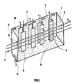
- FIG. 1 represents a perspective view of a nickel-plating tank cut lengthwise along a vertical plane placed a little in front of the plant of median symmetry .
- the tank 1 of parallelepiped shape whose small faces 2 are each pierced with three holes 3 through which pass three metal strands 4 which pass in the direction of the arrow 5 in the nickel plating bath 6.
- the electrodes and the screens are suspended in the bath by means not shown which allow them to be moved longitudinally and transversely in the tank.
- the bath is driven in a circulation movement from bottom to top by means of a pump, not shown, supplied by the flow of overflows 10 and which discharges said bath into the distribution ramp 11.
- a pump not shown
- a device comprising successively: - a first rinsing compartment with internal dimensions 1000 x 120 x 120 mm containing 9 liters of 70 ° C solution pumped from an 80-liter reserve tank - a rinsing compartment - an activation tank with internal dimensions 1000 x 120 x 120 mm fitted with electrodes with dimensions 100 x 80 x 80 mm connected to a negative current source capable of delivering 2000 A at 40 Volts and screens with dimensions 120 x 40 x 5 mm in polypropylene arranged so as to obtain a distribution of the judiciously chosen current density, said tank containing a solution at 45 ° C.
- nickel-plating tank with internal dimensions 1000 x 120 x 120 mm fitted with electrodes connected to the positive pole of the same current source which supplies the activation tank and screens of the same dimensions as those of the activation tank , the assembly being arranged according to Figure 1; this nickel-plating tank containing a solution at 65 ° C.
- the invention finds its application in the nickel plating of metallic wires in particular of aluminum, of any diameter and, in particular, less than 1 mm and allows obtaining by stranding and wiring of light and reliable electrical conductors which are particularly advantageous for equipping spacecraft. air or land transport where energy saving by reducing equipment is much appreciated.
Landscapes
- Chemical & Material Sciences (AREA)
- Engineering & Computer Science (AREA)
- Chemical Kinetics & Catalysis (AREA)
- Electrochemistry (AREA)
- Materials Engineering (AREA)
- Metallurgy (AREA)
- Organic Chemistry (AREA)
- Electroplating Methods And Accessories (AREA)
- Chemical Vapour Deposition (AREA)
- Physical Vapour Deposition (AREA)
- Medicines Containing Material From Animals Or Micro-Organisms (AREA)
- Nitrogen And Oxygen Or Sulfur-Condensed Heterocyclic Ring Systems (AREA)
- Non-Insulated Conductors (AREA)
- Conductive Materials (AREA)
Applications Claiming Priority (2)
| Application Number | Priority Date | Filing Date | Title |
|---|---|---|---|
| FR8700952 | 1987-01-06 | ||
| FR8700952A FR2609292B1 (fr) | 1987-01-06 | 1987-01-06 | Procede et dispositif pour deposer electrolytiquement au defile un film continu de nickel sur du fil metallique a usage electrique |
Publications (2)
| Publication Number | Publication Date |
|---|---|
| EP0276190A1 true EP0276190A1 (de) | 1988-07-27 |
| EP0276190B1 EP0276190B1 (de) | 1990-09-19 |
Family
ID=9347320
Family Applications (1)
| Application Number | Title | Priority Date | Filing Date |
|---|---|---|---|
| EP88420002A Expired - Lifetime EP0276190B1 (de) | 1987-01-06 | 1988-01-04 | Verfahren und Vorrichtung zum elektrolytischen Absetzen eines kontinuierlichen Nickelfilms auf Draht |
Country Status (16)
| Country | Link |
|---|---|
| US (1) | US4741811A (de) |
| EP (1) | EP0276190B1 (de) |
| JP (1) | JPS63213694A (de) |
| CN (1) | CN1008823B (de) |
| AT (1) | ATE56758T1 (de) |
| AU (1) | AU589106B2 (de) |
| BR (1) | BR8800017A (de) |
| CA (1) | CA1309690C (de) |
| DE (1) | DE3860610D1 (de) |
| DK (1) | DK388A (de) |
| ES (1) | ES2019995B3 (de) |
| FI (1) | FI880021A7 (de) |
| FR (1) | FR2609292B1 (de) |
| IS (1) | IS1431B6 (de) |
| NO (1) | NO880019L (de) |
| PT (1) | PT86493B (de) |
Families Citing this family (16)
| Publication number | Priority date | Publication date | Assignee | Title |
|---|---|---|---|---|
| BE1001859A3 (nl) * | 1988-10-06 | 1990-03-20 | Bekaert Sa Nv | Inrichting voor het continu electrolytisch behandelen van draadvormige voorwerpen. |
| JP2003533597A (ja) | 2000-05-18 | 2003-11-11 | コラス・アルミニウム・バルツプロドウクテ・ゲーエムベーハー | アルミニウム製品の製造方法 |
| US6796484B2 (en) | 2001-02-02 | 2004-09-28 | Corus Aluminum Walzprodukte Gmbh | Nickel-plated brazing product having improved corrosion performance |
| KR20030088462A (ko) | 2001-04-20 | 2003-11-19 | 코루스 알루미늄 발쯔프로두크테 게엠베하 | 알루미늄 소재의 전처리 및 도금 방법 |
| US6572743B2 (en) * | 2001-08-23 | 2003-06-03 | 3M Innovative Properties Company | Electroplating assembly for metal plated optical fibers |
| US6815086B2 (en) | 2001-11-21 | 2004-11-09 | Dana Canada Corporation | Methods for fluxless brazing |
| US6994919B2 (en) * | 2002-01-31 | 2006-02-07 | Corus Aluminium Walzprodukte Gmbh | Brazing product and method of manufacturing a brazing product |
| US7294411B2 (en) * | 2002-01-31 | 2007-11-13 | Aleris Aluminum Koblenz Gmbh | Brazing product and method of its manufacture |
| US7056597B2 (en) * | 2002-12-13 | 2006-06-06 | Corus Aluminium Walzprodukte Gmbh | Brazing sheet product and method of its manufacture |
| US7078111B2 (en) * | 2002-12-13 | 2006-07-18 | Corus Aluminium Walzprodukte Gmbh | Brazing sheet product and method of its manufacture |
| US20060157352A1 (en) * | 2005-01-19 | 2006-07-20 | Corus Aluminium Walzprodukte Gmbh | Method of electroplating and pre-treating aluminium workpieces |
| AU2006212875B2 (en) * | 2005-02-08 | 2011-06-02 | Dyno Nobel Inc. | Delay units and methods of making the same |
| AU2011224469B2 (en) | 2010-03-09 | 2014-08-07 | Dyno Nobel Inc. | Sealer elements, detonators containing the same, and methods of making |
| CN102790199B (zh) * | 2012-08-22 | 2015-08-05 | 陈伟洲 | 锂离子电池正极极耳及其制造方法 |
| CN103820831B (zh) * | 2014-02-13 | 2016-08-24 | 德清县佳伟线缆有限公司 | 一种金属线材的电镀处理设备 |
| CN118173330B (zh) * | 2024-05-14 | 2024-07-19 | 山东无棣海丰电缆有限公司 | 一种海洋电缆加工用防腐蚀处理装置 |
Citations (1)
| Publication number | Priority date | Publication date | Assignee | Title |
|---|---|---|---|---|
| FR2526052A1 (fr) * | 1982-04-29 | 1983-11-04 | Pechiney Aluminium | Procede et dispositif pour revetir une grande longueur de metal d'une couche metallique |
Family Cites Families (2)
| Publication number | Priority date | Publication date | Assignee | Title |
|---|---|---|---|---|
| US4097342A (en) * | 1975-05-16 | 1978-06-27 | Alcan Research And Development Limited | Electroplating aluminum stock |
| US4126522A (en) * | 1976-08-09 | 1978-11-21 | Telefonaktiebolaget L M Ericsson | Method of preparing aluminum wire for electrical conductors |
-
1987
- 1987-01-06 FR FR8700952A patent/FR2609292B1/fr not_active Expired
- 1987-02-27 US US07/019,666 patent/US4741811A/en not_active Expired - Fee Related
-
1988
- 1988-01-04 DK DK000388A patent/DK388A/da not_active Application Discontinuation
- 1988-01-04 AT AT88420002T patent/ATE56758T1/de not_active IP Right Cessation
- 1988-01-04 EP EP88420002A patent/EP0276190B1/de not_active Expired - Lifetime
- 1988-01-04 IS IS3303A patent/IS1431B6/is unknown
- 1988-01-04 DE DE8888420002T patent/DE3860610D1/de not_active Expired - Lifetime
- 1988-01-04 ES ES88420002T patent/ES2019995B3/es not_active Expired - Lifetime
- 1988-01-05 NO NO880019A patent/NO880019L/no unknown
- 1988-01-05 AU AU10059/88A patent/AU589106B2/en not_active Ceased
- 1988-01-05 CA CA000555884A patent/CA1309690C/fr not_active Expired - Lifetime
- 1988-01-05 FI FI880021A patent/FI880021A7/fi not_active Application Discontinuation
- 1988-01-05 BR BR8800017A patent/BR8800017A/pt unknown
- 1988-01-05 PT PT86493A patent/PT86493B/pt not_active IP Right Cessation
- 1988-01-06 JP JP63001137A patent/JPS63213694A/ja active Granted
- 1988-01-06 CN CN88100133.3A patent/CN1008823B/zh not_active Expired
Patent Citations (1)
| Publication number | Priority date | Publication date | Assignee | Title |
|---|---|---|---|---|
| FR2526052A1 (fr) * | 1982-04-29 | 1983-11-04 | Pechiney Aluminium | Procede et dispositif pour revetir une grande longueur de metal d'une couche metallique |
Also Published As
| Publication number | Publication date |
|---|---|
| FR2609292A1 (fr) | 1988-07-08 |
| JPH0317920B2 (de) | 1991-03-11 |
| CA1309690C (fr) | 1992-11-03 |
| DK388A (da) | 1988-07-07 |
| FI880021A0 (fi) | 1988-01-05 |
| EP0276190B1 (de) | 1990-09-19 |
| JPS63213694A (ja) | 1988-09-06 |
| NO880019L (no) | 1988-07-07 |
| BR8800017A (pt) | 1988-08-02 |
| AU589106B2 (en) | 1989-09-28 |
| AU1005988A (en) | 1988-07-07 |
| DK388D0 (da) | 1988-01-04 |
| ATE56758T1 (de) | 1990-10-15 |
| PT86493A (pt) | 1989-01-30 |
| FR2609292B1 (fr) | 1989-03-24 |
| IS1431B6 (is) | 1990-07-16 |
| US4741811A (en) | 1988-05-03 |
| DE3860610D1 (de) | 1990-10-25 |
| NO880019D0 (no) | 1988-01-05 |
| FI880021A7 (fi) | 1988-07-07 |
| CN1008823B (zh) | 1990-07-18 |
| IS3303A7 (is) | 1988-07-07 |
| PT86493B (pt) | 1993-08-31 |
| CN88100133A (zh) | 1988-07-20 |
| ES2019995B3 (es) | 1991-07-16 |
Similar Documents
| Publication | Publication Date | Title |
|---|---|---|
| EP0276190B1 (de) | Verfahren und Vorrichtung zum elektrolytischen Absetzen eines kontinuierlichen Nickelfilms auf Draht | |
| EP1647996B2 (de) | Verkupfertes Aluminium Strangkabel und sein Herstellungsverfahren | |
| EP1204787B1 (de) | Verfahren zum kontinuierlichen vernickeln eines aluminium-leiters und vorrichtung dazu | |
| FR2646174A1 (fr) | Procede et dispositif de revetement en continu de substrats conducteurs de l'electricite par electrolyse a grande vitesse | |
| EP0093681B1 (de) | Verfahren und Vorrichtung zur galvanischen Beschichtung von metallischen Bändern grosser Länge | |
| FR2525242A1 (fr) | Procede pour le depot electrolytique d'un alliage fe-zn | |
| FR2655275A2 (fr) | Perfectionnement au procede de fabrication d'un tube poreux revetu interieurement d'une membrane semi-permeable par electrophorese. | |
| FR2551467A1 (fr) | Procede et appareil permettant de realiser un depot electrolytique continu d'alliages | |
| EP0955396B1 (de) | Vorrichtung und Verfahren zum Herstellen von Drahtelektroden zum funkenerosiven Schneiden | |
| EP1106293B1 (de) | Drahtelektrode zum Funkenerodieren und Verfahren zur Herstellung | |
| FR2470170A1 (fr) | Procede de fabrication de fils metalliques pour le renforcement d'objets en caoutchouc | |
| EP0254703B1 (de) | Verfahren und Vorrichtung zum elektrolytischen Verzinken von Stahlband | |
| US4759837A (en) | Process and apparatus for electrolytically depositing in a moving mode a continuous film of nickel on metal wire for electrical use | |
| FR2576323A1 (fr) | Procede de traitement de profils conducteurs, notamment metalliques, installation pour sa mise en oeuvre et profils traites ainsi obtenus | |
| EP0693141B1 (de) | Verfahren und vorrichtung zur herstellung eines versilberten aluminiumleiters und leiter | |
| EP0288364A1 (de) | Verfahren zur Verbesserung des Verschleisswiderstandes der Innenseite eines Motors | |
| JPS6247497A (ja) | タイヤコ−ド用鋼線のメツキ方法 | |
| FR2732365A1 (fr) | Procede continu d'electrozingage de bande metallique dans un bain d'electrolyse a base de chlorures pour obtenir des revetements de faible rugosite sous des densites de courant elevees | |
| BE887824A (fr) | Appareil de traitement electrolytique d'un feuillard metallique | |
| BE1002222A6 (fr) | Procede pour appliquer par electrolyse une couche de cuivre sur un feuillard metallique. | |
| BE1004124A3 (fr) | Procede pour appliquer par electrolyse une couche d'un alliage nickel-cobalt sur un objet et solution d'electrolyte utilisee a cet effet. | |
| BE905588A (fr) | Dispositif de depot electrolytique et procede pour sa mise en oeuvre. | |
| BE1007569A6 (fr) | Procede d'electrodeposition d'un metal. | |
| LU86773A1 (fr) | Installation pour la fabrication en continu d'une feuille metallique extra-mince par depot electrolytique | |
| FR3060610A1 (fr) | Procede electrolytique pour extraire de l'etain et/ou du plomb compris dans un melange conducteur |
Legal Events
| Date | Code | Title | Description |
|---|---|---|---|
| PUAI | Public reference made under article 153(3) epc to a published international application that has entered the european phase |
Free format text: ORIGINAL CODE: 0009012 |
|
| AK | Designated contracting states |
Kind code of ref document: A1 Designated state(s): AT BE CH DE ES GB GR IT LI LU NL SE |
|
| 17P | Request for examination filed |
Effective date: 19880805 |
|
| 17Q | First examination report despatched |
Effective date: 19891227 |
|
| GRAA | (expected) grant |
Free format text: ORIGINAL CODE: 0009210 |
|
| AK | Designated contracting states |
Kind code of ref document: B1 Designated state(s): AT BE CH DE ES GB GR IT LI LU NL SE |
|
| PG25 | Lapsed in a contracting state [announced via postgrant information from national office to epo] |
Ref country code: GR Free format text: LAPSE BECAUSE OF FAILURE TO SUBMIT A TRANSLATION OF THE DESCRIPTION OR TO PAY THE FEE WITHIN THE PRESCRIBED TIME-LIMIT Effective date: 19900919 |
|
| REF | Corresponds to: |
Ref document number: 56758 Country of ref document: AT Date of ref document: 19901015 Kind code of ref document: T |
|
| GBT | Gb: translation of ep patent filed (gb section 77(6)(a)/1977) | ||
| ITF | It: translation for a ep patent filed | ||
| REF | Corresponds to: |
Ref document number: 3860610 Country of ref document: DE Date of ref document: 19901025 |
|
| PGFP | Annual fee paid to national office [announced via postgrant information from national office to epo] |
Ref country code: CH Payment date: 19901214 Year of fee payment: 4 |
|
| PGFP | Annual fee paid to national office [announced via postgrant information from national office to epo] |
Ref country code: SE Payment date: 19901217 Year of fee payment: 4 |
|
| PG25 | Lapsed in a contracting state [announced via postgrant information from national office to epo] |
Ref country code: AT Effective date: 19910104 |
|
| PG25 | Lapsed in a contracting state [announced via postgrant information from national office to epo] |
Ref country code: LU Free format text: LAPSE BECAUSE OF NON-PAYMENT OF DUE FEES Effective date: 19910131 |
|
| PGFP | Annual fee paid to national office [announced via postgrant information from national office to epo] |
Ref country code: NL Payment date: 19910131 Year of fee payment: 4 |
|
| PLBE | No opposition filed within time limit |
Free format text: ORIGINAL CODE: 0009261 |
|
| STAA | Information on the status of an ep patent application or granted ep patent |
Free format text: STATUS: NO OPPOSITION FILED WITHIN TIME LIMIT |
|
| 26N | No opposition filed | ||
| PG25 | Lapsed in a contracting state [announced via postgrant information from national office to epo] |
Ref country code: SE Effective date: 19920105 |
|
| PG25 | Lapsed in a contracting state [announced via postgrant information from national office to epo] |
Ref country code: LI Effective date: 19920131 Ref country code: CH Effective date: 19920131 |
|
| PG25 | Lapsed in a contracting state [announced via postgrant information from national office to epo] |
Ref country code: NL Effective date: 19920801 |
|
| NLV4 | Nl: lapsed or anulled due to non-payment of the annual fee | ||
| REG | Reference to a national code |
Ref country code: CH Ref legal event code: PL |
|
| PGFP | Annual fee paid to national office [announced via postgrant information from national office to epo] |
Ref country code: GB Payment date: 19921214 Year of fee payment: 6 |
|
| ITTA | It: last paid annual fee | ||
| PGFP | Annual fee paid to national office [announced via postgrant information from national office to epo] |
Ref country code: BE Payment date: 19930215 Year of fee payment: 6 |
|
| PG25 | Lapsed in a contracting state [announced via postgrant information from national office to epo] |
Ref country code: GB Effective date: 19940104 |
|
| PG25 | Lapsed in a contracting state [announced via postgrant information from national office to epo] |
Ref country code: BE Effective date: 19940131 |
|
| BERE | Be: lapsed |
Owner name: ALUMINIUM PECHINEY Effective date: 19940131 |
|
| GBPC | Gb: european patent ceased through non-payment of renewal fee |
Effective date: 19940104 |
|
| EUG | Se: european patent has lapsed |
Ref document number: 88420002.3 Effective date: 19920806 |
|
| PGFP | Annual fee paid to national office [announced via postgrant information from national office to epo] |
Ref country code: ES Payment date: 20000117 Year of fee payment: 13 |
|
| PG25 | Lapsed in a contracting state [announced via postgrant information from national office to epo] |
Ref country code: ES Free format text: LAPSE BECAUSE OF NON-PAYMENT OF DUE FEES Effective date: 20010105 |
|
| REG | Reference to a national code |
Ref country code: ES Ref legal event code: FD2A Effective date: 20020916 |
|
| PG25 | Lapsed in a contracting state [announced via postgrant information from national office to epo] |
Ref country code: IT Free format text: LAPSE BECAUSE OF NON-PAYMENT OF DUE FEES;WARNING: LAPSES OF ITALIAN PATENTS WITH EFFECTIVE DATE BEFORE 2007 MAY HAVE OCCURRED AT ANY TIME BEFORE 2007. THE CORRECT EFFECTIVE DATE MAY BE DIFFERENT FROM THE ONE RECORDED. Effective date: 20050104 |
|
| PGFP | Annual fee paid to national office [announced via postgrant information from national office to epo] |
Ref country code: DE Payment date: 20061215 Year of fee payment: 20 |