EP0276372A1 - Arbre à cames dans un moteur à combustion interne - Google Patents
Arbre à cames dans un moteur à combustion interne Download PDFInfo
- Publication number
- EP0276372A1 EP0276372A1 EP87115410A EP87115410A EP0276372A1 EP 0276372 A1 EP0276372 A1 EP 0276372A1 EP 87115410 A EP87115410 A EP 87115410A EP 87115410 A EP87115410 A EP 87115410A EP 0276372 A1 EP0276372 A1 EP 0276372A1
- Authority
- EP
- European Patent Office
- Prior art keywords
- camshaft
- housing
- cylinder head
- holder
- bearing housing
- Prior art date
- Legal status (The legal status is an assumption and is not a legal conclusion. Google has not performed a legal analysis and makes no representation as to the accuracy of the status listed.)
- Granted
Links
Images


Classifications
-
- F—MECHANICAL ENGINEERING; LIGHTING; HEATING; WEAPONS; BLASTING
- F01—MACHINES OR ENGINES IN GENERAL; ENGINE PLANTS IN GENERAL; STEAM ENGINES
- F01L—CYCLICALLY OPERATING VALVES FOR MACHINES OR ENGINES
- F01L1/00—Valve-gear or valve arrangements, e.g. lift-valve gear
- F01L1/02—Valve drive
- F01L1/04—Valve drive by means of cams, camshafts, cam discs, eccentrics or the like
- F01L1/047—Camshafts
- F01L1/053—Camshafts overhead type
- F01L1/0532—Camshafts overhead type the cams being directly in contact with the driven valve
-
- F—MECHANICAL ENGINEERING; LIGHTING; HEATING; WEAPONS; BLASTING
- F01—MACHINES OR ENGINES IN GENERAL; ENGINE PLANTS IN GENERAL; STEAM ENGINES
- F01L—CYCLICALLY OPERATING VALVES FOR MACHINES OR ENGINES
- F01L1/00—Valve-gear or valve arrangements, e.g. lift-valve gear
- F01L1/46—Component parts, details, or accessories, not provided for in preceding subgroups
Definitions
- the invention relates to a camshaft for an internal combustion engine, which is used to actuate valves and is arranged in bearings of housings of the internal combustion engine formed by a cylinder head and a camshaft bearing housing.
- a known camshaft (FR-PS 1 511 082) is arranged in bearings which are represented by housings of an internal combustion engine which are assembled in one plane and are designed as a cylinder head and camshaft bearing housing.
- the camshaft bearing housing which has the shape of a hood, is held on the cylinder head by means of screws. If the camshaft bearing housing is released, several tappets of valves under spring force move the camshaft into a position outside the design position.
- the object of the invention is to take such precautions on a camshaft that their assembly in bearings which are formed by a camshaft bearing housing and a cylinder head is simple.
- the holder holds the camshaft in a housing - cylinder head or camshaft bearing housing - in a preassembled position, which makes it easier to connect the housings forming the camshaft bearings because the camshaft is already in one of the design positions similar position. It is also ensured by the holder that when a housing, for example the camshaft bearing housing, is released, the camshaft remains in a position which is easier to handle.
- the brackets can be used to pre-adjust the two housings - cylinder head and camshaft bearing housing - relative to one another.
- the holders are simple components and can be attached to one of the two housings without much effort
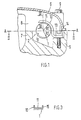
- a camshaft 1 for actuating valves, not shown, held under spring tension, is arranged in bearings 2, 3, 4, which are formed by the housing of an internal combustion engine.
- the housings are a cylinder head 5 and a hood-shaped camshaft bearing housing 6, which are assembled in a parting plane AA running perpendicular to the cylinder axis (not shown), each bearing comprising 2 bearing halves 7, 8, which fit into the cylinder head 5 or the camshaft bearing housing 6 are integrated.
- the camshaft housing 6 is held on the cylinder head 5 by means of several screws 9.
- the camshaft 1 cooperates with a holder 10 in such a way that it forms a preassembled structural unit with the cylinder head 5.
- the holder 10 has a ring-like support section 11 which surrounds a part of the shaft region 12 of the camshaft 1 at a short distance, ie the radius R1 of the support section 11 is larger than the radius R2 of the camshaft 1.
- the holder 10 is with a mounting flange 13th provided, which extends laterally from the camshaft 1 - parallel to the plane AA - and is held on the cylinder head 5 by means of a screw 14.
- two holders 10 are provided over the length of the camshaft 1, which are identical in construction.
- camshaft housing 6 If the camshaft housing 6 is detached from the cylinder head 5, the camshaft 1 assumes position B due to the valves held under spring tension; it remains in an easy-to-use basic position.
- the holder 16 surrounds the shaft region 12 of the camshaft 1 with a half-shell-shaped support section 17, it being provided with fastening flanges 18, 19 which extend on both sides of the camshaft 1 - parallel to the plane A-A.
- the mounting flanges 18, 19 are held on the camshaft bearing housing 6 with screws 20, 21.
- the camshaft 1 forms a preassembled unit with the camshaft housing 1 through the holder 16, the camshaft 1 having the position C.
- camshaft 1 can also cooperate with a holder 22, which is represented by a straight cylindrical pin 23.
- the pin 23 extends obliquely to the plane A-A and projects beyond the camshaft 1, wherein it is fixed in a bore 24 in the cylinder head 5.
Landscapes
- Engineering & Computer Science (AREA)
- Mechanical Engineering (AREA)
- General Engineering & Computer Science (AREA)
- Valve-Gear Or Valve Arrangements (AREA)
Applications Claiming Priority (2)
| Application Number | Priority Date | Filing Date | Title |
|---|---|---|---|
| DE3643673 | 1986-12-20 | ||
| DE19863643673 DE3643673A1 (de) | 1986-12-20 | 1986-12-20 | Nockenwelle fuer eine brennkraftmaschine |
Publications (2)
| Publication Number | Publication Date |
|---|---|
| EP0276372A1 true EP0276372A1 (fr) | 1988-08-03 |
| EP0276372B1 EP0276372B1 (fr) | 1990-09-26 |
Family
ID=6316712
Family Applications (1)
| Application Number | Title | Priority Date | Filing Date |
|---|---|---|---|
| EP87115410A Expired - Lifetime EP0276372B1 (fr) | 1986-12-20 | 1987-10-21 | Arbre à cames dans un moteur à combustion interne |
Country Status (5)
| Country | Link |
|---|---|
| US (1) | US4821693A (fr) |
| EP (1) | EP0276372B1 (fr) |
| JP (1) | JP2654041B2 (fr) |
| DE (2) | DE3643673A1 (fr) |
| ES (1) | ES2018527B3 (fr) |
Families Citing this family (5)
| Publication number | Priority date | Publication date | Assignee | Title |
|---|---|---|---|---|
| US5119776A (en) * | 1991-09-30 | 1992-06-09 | Chrysler Corporation | Compact bearing cap for overhead camshaft |
| FR2915512B1 (fr) * | 2007-04-30 | 2011-08-19 | Timken Co | Ensemble d'arbre et d'un support et procede de montage correspondant |
| DE102008007091B4 (de) | 2008-01-31 | 2010-06-24 | Polytec Automotive Gmbh & Co. Kg | Nockenwellenmodul |
| DE102009009664A1 (de) | 2009-02-19 | 2010-08-26 | Mahle International Gmbh | Nockenwelle |
| DE102013113824A1 (de) * | 2013-12-11 | 2015-06-11 | Dr. Ing. H.C. F. Porsche Aktiengesellschaft | Verfahren zum Montieren einer Nockenwelle |
Citations (3)
| Publication number | Priority date | Publication date | Assignee | Title |
|---|---|---|---|---|
| GB558779A (en) * | 1943-05-19 | 1944-01-20 | Harold Raymond Morgan | Improvements in combustion chambers and overhead valve gear in internal combustion engines |
| FR1217835A (fr) * | 1958-12-10 | 1960-05-05 | Simca Automobiles Sa | Perfectionnements apportés aux moteurs à arbre à cames en tête |
| FR1511082A (fr) * | 1966-12-15 | 1968-01-26 | Peugeot | Nouvel agencement de l'arbre à cames sur un moteur thermique ou compresseur et machine en résultant |
Family Cites Families (7)
| Publication number | Priority date | Publication date | Assignee | Title |
|---|---|---|---|---|
| US1840314A (en) * | 1929-10-22 | 1932-01-12 | Gerard Paul | Valve actuating mechanism for internal combustion engines |
| JPS5325711A (en) * | 1976-08-20 | 1978-03-09 | Toyota Motor Corp | Cam shaft bearing structure for engine |
| DE3217203A1 (de) * | 1981-05-15 | 1982-12-02 | Honda Giken Kogyo K.K., Tokyo | Variable ventilsteuerung |
| SU1044801A1 (ru) * | 1981-11-26 | 1983-09-30 | Pisotskij Polikarp Z | Газораспределительный механизм |
| JPS5967509U (ja) * | 1982-10-27 | 1984-05-08 | 本田技研工業株式会社 | 内燃エンジンにおけるカム軸の軸受装置 |
| JPS5999149U (ja) * | 1982-12-23 | 1984-07-04 | トヨタ自動車株式会社 | 内燃機関のシリンダヘツド |
| DE8503825U1 (de) * | 1985-02-12 | 1986-06-05 | Johnson, Edward, West Harford | Zylinderkopf für Verbrennungsmotoren |
-
1986
- 1986-12-20 DE DE19863643673 patent/DE3643673A1/de active Granted
-
1987
- 1987-10-21 ES ES87115410T patent/ES2018527B3/es not_active Expired - Lifetime
- 1987-10-21 DE DE8787115410T patent/DE3765245D1/de not_active Expired - Lifetime
- 1987-10-21 EP EP87115410A patent/EP0276372B1/fr not_active Expired - Lifetime
- 1987-12-11 US US07/131,502 patent/US4821693A/en not_active Expired - Fee Related
- 1987-12-18 JP JP62319169A patent/JP2654041B2/ja not_active Expired - Lifetime
Patent Citations (3)
| Publication number | Priority date | Publication date | Assignee | Title |
|---|---|---|---|---|
| GB558779A (en) * | 1943-05-19 | 1944-01-20 | Harold Raymond Morgan | Improvements in combustion chambers and overhead valve gear in internal combustion engines |
| FR1217835A (fr) * | 1958-12-10 | 1960-05-05 | Simca Automobiles Sa | Perfectionnements apportés aux moteurs à arbre à cames en tête |
| FR1511082A (fr) * | 1966-12-15 | 1968-01-26 | Peugeot | Nouvel agencement de l'arbre à cames sur un moteur thermique ou compresseur et machine en résultant |
Also Published As
| Publication number | Publication date |
|---|---|
| DE3643673C2 (fr) | 1990-04-19 |
| US4821693A (en) | 1989-04-18 |
| EP0276372B1 (fr) | 1990-09-26 |
| ES2018527B3 (es) | 1991-04-16 |
| JPS63162909A (ja) | 1988-07-06 |
| JP2654041B2 (ja) | 1997-09-17 |
| DE3643673A1 (de) | 1988-06-30 |
| DE3765245D1 (de) | 1990-10-31 |
Similar Documents
| Publication | Publication Date | Title |
|---|---|---|
| DE3909458B4 (de) | Kettenradhalterungs- und Kettenführungselement | |
| DE3426208C1 (de) | Kurbelwellenlager fuer Brennkraftmaschinen | |
| EP0504128B1 (fr) | Culasse de moteur à combustion interne | |
| DE2557967C3 (de) | Kühlerbefestigung eines Kraftfahrzeuges | |
| EP1021321B1 (fr) | Systeme d'essuie-glace pour vehicules | |
| DE3326321C2 (fr) | ||
| DE3519205C2 (fr) | ||
| DE69612087T2 (de) | Kipphebelvorrichtung für brennkraftmaschine | |
| EP0799749B1 (fr) | Dispositif de retenue pour un groupe propulseur | |
| EP0075659B1 (fr) | Moteur à combustion à quatre cylindres | |
| DE602004000201T2 (de) | Verbindungsstange zwischen zwei mechanischen Teilen | |
| DE3728268C2 (fr) | ||
| EP0276372B1 (fr) | Arbre à cames dans un moteur à combustion interne | |
| DE19607819A1 (de) | Kettentrieb-Einheit für den Nockenwellen-Antrieb einer Brennkraftmaschine | |
| DE2849860A1 (de) | Geraeuscharme brennkraftmaschine | |
| EP0228533B1 (fr) | Moteur à combustion interne avec au moins un arbre à came en tête | |
| EP0907008A1 (fr) | Culasse avec commande de soupape pour moteur à combustion interne | |
| DE2711938A1 (de) | Geteiltes gleitlager, insbesondere pleuellager | |
| EP3450706A1 (fr) | Dispositif de logement rotatif d'un arbre à cames | |
| DE3419184A1 (de) | Zuendverteileranordnung an brennkraftmaschinen | |
| DE1198606B (de) | Ventilsteuerung fuer eine Brennkraftmaschine mit obenliegender Nockenwelle | |
| DE69302735T2 (de) | Schiebegelenkverbindung | |
| DE10257234A1 (de) | Spannvorrichtung für eine Brennkraftmaschine | |
| DE69502511T2 (de) | Zusammenbau einer Kipphebelwelle in einem Zylinderkopf einer Brennkraftmaschine | |
| DE19600441A1 (de) | Zylinderkopf einer Brennkraftmaschine |
Legal Events
| Date | Code | Title | Description |
|---|---|---|---|
| PUAI | Public reference made under article 153(3) epc to a published international application that has entered the european phase |
Free format text: ORIGINAL CODE: 0009012 |
|
| AK | Designated contracting states |
Kind code of ref document: A1 Designated state(s): DE ES FR GB IT NL SE |
|
| 17P | Request for examination filed |
Effective date: 19881205 |
|
| 17Q | First examination report despatched |
Effective date: 19891030 |
|
| GRAA | (expected) grant |
Free format text: ORIGINAL CODE: 0009210 |
|
| AK | Designated contracting states |
Kind code of ref document: B1 Designated state(s): DE ES FR GB IT NL SE |
|
| ITF | It: translation for a ep patent filed | ||
| REF | Corresponds to: |
Ref document number: 3765245 Country of ref document: DE Date of ref document: 19901031 |
|
| GBT | Gb: translation of ep patent filed (gb section 77(6)(a)/1977) | ||
| ET | Fr: translation filed | ||
| PLBE | No opposition filed within time limit |
Free format text: ORIGINAL CODE: 0009261 |
|
| STAA | Information on the status of an ep patent application or granted ep patent |
Free format text: STATUS: NO OPPOSITION FILED WITHIN TIME LIMIT |
|
| 26N | No opposition filed | ||
| ITTA | It: last paid annual fee | ||
| PGFP | Annual fee paid to national office [announced via postgrant information from national office to epo] |
Ref country code: SE Payment date: 19931005 Year of fee payment: 7 |
|
| PGFP | Annual fee paid to national office [announced via postgrant information from national office to epo] |
Ref country code: ES Payment date: 19931019 Year of fee payment: 7 |
|
| PGFP | Annual fee paid to national office [announced via postgrant information from national office to epo] |
Ref country code: NL Payment date: 19931031 Year of fee payment: 7 |
|
| PG25 | Lapsed in a contracting state [announced via postgrant information from national office to epo] |
Ref country code: SE Effective date: 19941022 Ref country code: ES Free format text: LAPSE BECAUSE OF EXPIRATION OF PROTECTION Effective date: 19941022 |
|
| EAL | Se: european patent in force in sweden |
Ref document number: 87115410.0 |
|
| PG25 | Lapsed in a contracting state [announced via postgrant information from national office to epo] |
Ref country code: NL Effective date: 19950501 |
|
| NLV4 | Nl: lapsed or anulled due to non-payment of the annual fee | ||
| EUG | Se: european patent has lapsed |
Ref document number: 87115410.0 |
|
| PGFP | Annual fee paid to national office [announced via postgrant information from national office to epo] |
Ref country code: GB Payment date: 19951012 Year of fee payment: 9 |
|
| PGFP | Annual fee paid to national office [announced via postgrant information from national office to epo] |
Ref country code: FR Payment date: 19951030 Year of fee payment: 9 Ref country code: DE Payment date: 19951030 Year of fee payment: 9 |
|
| PG25 | Lapsed in a contracting state [announced via postgrant information from national office to epo] |
Ref country code: GB Effective date: 19961021 |
|
| GBPC | Gb: european patent ceased through non-payment of renewal fee |
Effective date: 19961021 |
|
| PG25 | Lapsed in a contracting state [announced via postgrant information from national office to epo] |
Ref country code: FR Effective date: 19970630 |
|
| PG25 | Lapsed in a contracting state [announced via postgrant information from national office to epo] |
Ref country code: DE Effective date: 19970701 |
|
| REG | Reference to a national code |
Ref country code: FR Ref legal event code: ST |
|
| REG | Reference to a national code |
Ref country code: ES Ref legal event code: FD2A Effective date: 19990601 |
|
| PG25 | Lapsed in a contracting state [announced via postgrant information from national office to epo] |
Ref country code: IT Free format text: LAPSE BECAUSE OF NON-PAYMENT OF DUE FEES;WARNING: LAPSES OF ITALIAN PATENTS WITH EFFECTIVE DATE BEFORE 2007 MAY HAVE OCCURRED AT ANY TIME BEFORE 2007. THE CORRECT EFFECTIVE DATE MAY BE DIFFERENT FROM THE ONE RECORDED. Effective date: 20051021 |