EP0277778A2 - Production de cassettes à bandes préenregistrées - Google Patents
Production de cassettes à bandes préenregistrées Download PDFInfo
- Publication number
- EP0277778A2 EP0277778A2 EP88300752A EP88300752A EP0277778A2 EP 0277778 A2 EP0277778 A2 EP 0277778A2 EP 88300752 A EP88300752 A EP 88300752A EP 88300752 A EP88300752 A EP 88300752A EP 0277778 A2 EP0277778 A2 EP 0277778A2
- Authority
- EP
- European Patent Office
- Prior art keywords
- tape
- recorded
- data
- signals
- recording
- Prior art date
- Legal status (The legal status is an assumption and is not a legal conclusion. Google has not performed a legal analysis and makes no representation as to the accuracy of the status listed.)
- Granted
Links
Images



Classifications
-
- G—PHYSICS
- G11—INFORMATION STORAGE
- G11B—INFORMATION STORAGE BASED ON RELATIVE MOVEMENT BETWEEN RECORD CARRIER AND TRANSDUCER
- G11B27/00—Editing; Indexing; Addressing; Timing or synchronising; Monitoring; Measuring tape travel
- G11B27/10—Indexing; Addressing; Timing or synchronising; Measuring tape travel
- G11B27/19—Indexing; Addressing; Timing or synchronising; Measuring tape travel by using information detectable on the record carrier
- G11B27/28—Indexing; Addressing; Timing or synchronising; Measuring tape travel by using information detectable on the record carrier by using information signals recorded by the same method as the main recording
- G11B27/32—Indexing; Addressing; Timing or synchronising; Measuring tape travel by using information detectable on the record carrier by using information signals recorded by the same method as the main recording on separate auxiliary tracks of the same or an auxiliary record carrier
- G11B27/322—Indexing; Addressing; Timing or synchronising; Measuring tape travel by using information detectable on the record carrier by using information signals recorded by the same method as the main recording on separate auxiliary tracks of the same or an auxiliary record carrier used signal is digitally coded
- G11B27/324—Duty cycle modulation of control pulses, e.g. VHS-CTL-coding systems, RAPID-time code, VASS- or VISS-cue signals
-
- G—PHYSICS
- G11—INFORMATION STORAGE
- G11B—INFORMATION STORAGE BASED ON RELATIVE MOVEMENT BETWEEN RECORD CARRIER AND TRANSDUCER
- G11B23/00—Record carriers not specific to the method of recording or reproducing; Accessories, e.g. containers, specially adapted for co-operation with the recording or reproducing apparatus ; Intermediate mediums; Apparatus or processes specially adapted for their manufacture
- G11B23/02—Containers; Storing means both adapted to cooperate with the recording or reproducing means
- G11B23/113—Apparatus or processes specially adapted for the manufacture of magazines or cassettes, e.g. initial loading into container
-
- G—PHYSICS
- G11—INFORMATION STORAGE
- G11B—INFORMATION STORAGE BASED ON RELATIVE MOVEMENT BETWEEN RECORD CARRIER AND TRANSDUCER
- G11B23/00—Record carriers not specific to the method of recording or reproducing; Accessories, e.g. containers, specially adapted for co-operation with the recording or reproducing apparatus ; Intermediate mediums; Apparatus or processes specially adapted for their manufacture
- G11B23/38—Visual features other than those contained in record tracks or represented by sprocket holes the visual signals being auxiliary signals
- G11B23/40—Identifying or analogous means applied to or incorporated in the record carrier and not intended for visual display simultaneously with the playing-back of the record carrier, e.g. label, leader, photograph
-
- G—PHYSICS
- G11—INFORMATION STORAGE
- G11B—INFORMATION STORAGE BASED ON RELATIVE MOVEMENT BETWEEN RECORD CARRIER AND TRANSDUCER
- G11B27/00—Editing; Indexing; Addressing; Timing or synchronising; Monitoring; Measuring tape travel
- G11B27/10—Indexing; Addressing; Timing or synchronising; Measuring tape travel
- G11B27/19—Indexing; Addressing; Timing or synchronising; Measuring tape travel by using information detectable on the record carrier
- G11B27/28—Indexing; Addressing; Timing or synchronising; Measuring tape travel by using information detectable on the record carrier by using information signals recorded by the same method as the main recording
- G11B27/32—Indexing; Addressing; Timing or synchronising; Measuring tape travel by using information detectable on the record carrier by using information signals recorded by the same method as the main recording on separate auxiliary tracks of the same or an auxiliary record carrier
- G11B27/322—Indexing; Addressing; Timing or synchronising; Measuring tape travel by using information detectable on the record carrier by using information signals recorded by the same method as the main recording on separate auxiliary tracks of the same or an auxiliary record carrier used signal is digitally coded
-
- G—PHYSICS
- G11—INFORMATION STORAGE
- G11B—INFORMATION STORAGE BASED ON RELATIVE MOVEMENT BETWEEN RECORD CARRIER AND TRANSDUCER
- G11B5/00—Recording by magnetisation or demagnetisation of a record carrier; Reproducing by magnetic means; Record carriers therefor
- G11B5/86—Re-recording, i.e. transcribing information from one magnetisable record carrier on to one or more similar or dissimilar record carriers
-
- G—PHYSICS
- G11—INFORMATION STORAGE
- G11B—INFORMATION STORAGE BASED ON RELATIVE MOVEMENT BETWEEN RECORD CARRIER AND TRANSDUCER
- G11B2220/00—Record carriers by type
- G11B2220/90—Tape-like record carriers
Definitions
- This invention relates to a method and apparatus for recording and loading magnetic tape cassettes.
- magnetic tape cassette will be understood to relate to an assembly comprising an enclosing casing or shell housing two spools wound with a length of magnetic tape.
- Such cassettes are widely known for use with audio or video equipment and also as a recording store of data for computers. Regardless of its intended function the magnetic tape carried on the spools is of substantially the same form, comprising a flexible supporting substrate on one face of which there is formed an oxide layer exhibiting specific magnetic properties.
- the most well known types of cassettes are the Phillips "compact" cassette for audio and data information and the JVC "VHS" cassette for video information.
- Magnetic tape for use in such cassettes is manufactured in rolls many thousands of metres long sufficient to fill very many cassettes.
- This tape is wound into the plastic housings or shells to form cassettes using a special machine known as a cassette loader.
- the information to be stored on the magnetic tape may be recorded after the tape has been loaded into the cassettes ("in-cassette duplication") or may be recorded before loading into the cassettes ("reel-to-reel duplication"). If the tape is recorded before being loaded into cassettes this is usually achieved by recording the same programme repeatedly onto a length of tape sufficient to fill several cassettes, and then loading a length of the tape containing one programme into each of several cassettes sequentially.
- the term "programme” will be understood to mean a complete set of use signals, be they video or audio signals for entertainment or education purposes, or data signals for operating a computer or seving as the working basis for computer operation) it is necessary to leave a certain unrecorded length of tape between the end of a recorded programme and the commencement of the next adjacent recorded programme. It has also been known to record identifiable "cue tones" at the beginning or end (or both) of the programme material so that the physical break in the tape can with certainty be made in such a way that it does not impinge on the recorded programme material. In this way, the loader can detect the correct point to complete one cassette and start the next.
- programme material can be recorded at high speed in reel-to-reel recording machines having large-diameter reels of use tape, special machines having been developed for this purpose.
- magnetic use tape equivalent to about 30 to 40 C 60 cassettes is recorded in this way from a length of "master" tape on which the programme information has been recorded with high fidelity.
- the Sony Sprinter system passes a master tape carrying a "mirror image" of the magnetic recording station at which the two tapes are pressed together with a magnetic field applied so that the mirror image magnetic pattern is transferred reversely.
- the two tapes are stationary relative to each other and thus both may be transported at high speed through the recording station.
- This speed facility reduces the space requirements for a particular production level relative to the large space which would otherwise be needed.
- Quality recording requires a very strongly recorded master tape which is difficult to produce, production requiring specialist expensive recording techniques, and the print-through recorder is also itself expensive to produce since video copiers for commercial cassette production operations represent a small market, whose supply involves the economic disadvantage of small scale production operations.
- the Tape Automation ETD system comprises a recording head for recording the programme material onto use tape, and a pair of independantly operative motors (for example stepping motors) for effecting rim drive of each of two non-cassette (open) spools which are in use mounted to the apparatus for rotation about a common axis in parallel juxtaposed planes of rotation, one such spool serving as a supply spool which in use discharges use tape to the recording head and the other such spool serving as a take-up spool to take up recorded tape issuing from the recording head.
- independantly operative motors for example stepping motors
- the stepper motors are operable subject to control means for detecting changes in speed of tape supply and take-up whereby the relative speed of driven rotation of the spools can be adjusted to equalise tape supply to and tape take-up from the recording head.
- the space requirements of the machine are no more than about 25 per cent more than for conventional in-cassette mass copiers, an acceptable increase in practice.
- the spools of tape used in this system are very large diameter unbraced spools, that is the tape is wound on a core without the guiding discs conventionally used on open reels. By winding the tape at the correct high tension such open spools can be made hard and effectively self-supporting. They are known as "pancake" spools for obvious reasons.
- the technical problem to which the present invention relates is that of unambiguously and automatically identifying the programme material recorded on a length of tape to enable the programme content of a casssette containing such tape to be identified without the need to play back the tape.
- a method of recording magnetic tape for subsequent loading into cassettes in which between signals representing the programme material recorded along sections of the tape there are recorded signals representing data related to and/or identifying the programme material and which, upon playback of the tape act to control a cassette loading machine and/or apparatus such as a label printer associated therewith.
- signals representing the programme material and the data are recorded onto the magnetic tape by transporting the tape past a recording head or transducer at a recording station and in any event the programme material is preferably recorded from a master recording made on a recording medium (e.g. a master cassette) on which only the programme material is recorded (although, in fact, some of the data may also be recorded on the master).
- a master may first be sub-mastered to provide one or a plurality of sub-master recordings each used to record part of a very large number of programme copies onto magnetic tape on open or pancake spools, each sub-master having data encoded thereon to identify it as distinct from its parent and other sub-master(s).
- the programme material may be recorded onto magentic tape by transporting the said magnetic tape and a tape carrying a master recording of the programme material through a recording station including means for pressing the two tapes into close contact in an applied magnetic field to induce magnetic "print-through" of the recorded signal from the master recording tape onto the use tape.
- the magnetic tape is recorded with the programme material and data by transporting it through the recording station from an open supply spool to an open take-up spool.
- a method of producing cassettes of magnetic tape recorded with programme material comprising the steps of preparing a reel of tape having a plurality of lengths recorded with programme material intercalated with recorded signals representing data, transferring the reel to a cassette loader having a transducer responsive to the said recorded data signals, transporting tape into a casssette past the said transducer, controlling the operation of the tape transport in dependence on signals generated by the said transducer, and further controlling means for forming visible indicia representing the identity of the programme material recorded on the tape for application to the shell of the cassette.
- the means for forming the visible indicia may comprise a label printer and the method may then include the step of automatically applying a label printed with indicia corresponding to the said data signals onto the shell of the cassette during winding of the length of tape recorded with the programme material to which the data relates or immediately thereafter.
- the said means for forming visible indicia comprise means for directly marking or engraving the shell of the cassette being loaded during winding of the tape or immediately thereafter.
- the data signals detected by the said transducer may include data representing the length of tape occupied by programme material to which the data relates, and the method includes the step of storing the data length signal after detection thereof, generating signals representing the displacement of tape during winding thereof, comparing the said displacement-representative signals with the said stored signals and initiating deceleration of the tape transport when there is a predetermined difference therebetween.
- the present invention also comprehends magnetic tape recorded along successive lengths thereof with first signals representing programme material and second signals representing data indentifying the recorded programme material and/or one or more characteristics of the recorded tape and/or its production, the said second signals acting to control the operation of a cassette loader and/or associated apparatus upon detection thereof by a transducer sensitive to the magnetic recording on the tape.
- the said first signals are television signals and the said second signals are recorded on the tape in pulse code form.
- pulse code signals are preferably recorded on the tape as pulse width modulation of the signal recorded on the sync track of the video recording.
- the said recording transducer means may comprise a simple recording transducer or two separate transducers spaced along the path of the magnetic tape, one for recording signals representing programme material and one for recording signals representing data.
- apparatus for producing cassettes of recorded magnetic tape comprising apparatus as defined above for producing successive recordings of programme material and data onto a length of magnetic tape, means for winding the tape onto open spools after recording, a transducer sensitive to the recorded data signals and operative to generate electrical control signals in response thereto, a cassette loader having a drive spindle engageable with a spool of a cassette to be loaded, drive means for the spindle, a control circuit operative to control the spindle drive means in accordance with electrical control signals received from the said sensor, and cassette identification means operative to provide visible indicia representative of the programme identified by the data signal.
- the said cassette identification means comprises a label printer operative to print labels bearing indicia determined by the said data signals, and there are further provided means for applying the labels to cassette shells before being ejected from the cassette loader.
- the label printer may operate to produce indicia in the form of machine readable bar codes on the labels to be applied to the cassettes, in which case there are preferably provided means for reading the bar code labels and directing the cassettes to one of a plurality of label application stations at which preliminarily prepared labels from a stack thereof are applied to the cassettes.
- the bar codes are read by means which directs the cassettes to one of a plurality of packing stations or the bar codes are read and the cassettes sorted and directed to storage. Of course, read could be effected at a station and label selection effected thereat.
- the invention can be considered as a system for encoding serial binary data by asynchronous modulation of a regularly occurring event signal, in which the event signal is interrupted to encode the binary data and decoding of the interrupted event signal to regenerate the binary data is effected by determining the length of successive periods in which the event signal is interrupted and uninterrupted respectively.
- the present invention can thus be considered to include a system for recording serial binary data onto a magnetic tape in the presence of a regular signal recorded thereon, in which the binary data is recorded as asynchronous interruptions of the regular signal.
- the regular signal is the synchronisation control signal recorded along the edge of a video tape and the interruptions are formed either by selective erasure of a previously recorded synchronisation control signal or by selective inhibition of the recoding transducer by which the synchronisation control signal is recorded, and selective inhibition of the recording transducer may be effected by short-circuiting the recording transducer during the intervals for which the synchronisation control signal is to be interrupted.
- a programme duplication assembly comprising a master playback machine 11, a main recording controller 12 having a keyboard 13 for inputting information, and a bank of tape recorders for recording the video output of the master playback machine 11 and the data output of the main recording controller 12.
- the slave tape recorders which are identified with the reference numeral 141 to 14 n (where n, as mentioned above, may typically be 500 or in some cases may be 1000 or more) are equipped with drive means for carrying large open spools or pancake reels 15 from which tape is drawn over a capstan past two spaced recording heads 16,17 onto a futher open spool or pancake reel 18.
- the master playback machine is a conventional high quality video recorder, of the type generally available for domestic or professional use, modified so that video signals from a master programme cassette are output not to a VDU but to a programme output line 19 leading to the recording heads 16 of the recording machine 14 i in parallel.
- the recording machines may have a construction and operation as described and illustrated in our European Patent Application No 87 307713.5.
- the bank of recorders 14 may comprise several hundred such recorders all receiving the same video signals derived from the master playback machine and the master cassette run thereon. Typically, about 500 recorders may be present in the bank.
- Each of the recording heads 17 is connected to a line 20 on which are applied data signals from the main recording controller 12, which in this embodiment comprises a suitably programmed interface computer.
- the computer also has a control output line 21 for conveying signals for controlling the production of "local" information derived directly from the individual recorders 14, such as a recorder identification code, which is thus recorded at appropriate points along the tape as controlled by the interface computer: this latter is also connected directly to the master playback machine 11 by a line 22 for the purpose of detecting the beginning and end of the programme material and for monitoring and/or controlling a pause period while the playback machine 11 rewinds for a subsequent run or while the cassette is replaced with another containing the same or a different programme.
- a control output line 21 for conveying signals for controlling the production of "local" information derived directly from the individual recorders 14, such as a recorder identification code, which is thus recorded at appropriate points along the tape as controlled by the interface computer: this latter is also connected directly to the master playback machine 11 by a line 22 for the purpose of detecting the beginning and end of the programme material and for monitoring and/or controlling a pause period while the playback machine 11 rewinds for a subsequent run or while the cassette
- the interface computer 12 links the master playback machine 11 to the bank of recorders 14 and controls each production run on the basis of a production plan input to the computer via the keyboard 13 before the run is started (or afterwards and prior to playback of the master cassette to the end of the first master programme). Once a production run is complete, the computer prompts manual loading of the next master cassette and recycles.
- the single control line 20 transmits global information output of the interface computer 12 to each recorder 14 in the recorder bank, the second line 21 being used to transmit trigger signals as discussed above.
- the cassette loading station comprises at least one cassette loader generally indicated 30, which in this embodiment is of the type described and illustrated in our European Patent Application No 0 210 844A.
- the loader 30 is one of a plurality of such loaders the number of which will depend entirely on the number of recorders 14 in the bank of recorders, but due to the much faster speed of loading as compared to recording, the number of loaders 30 will be much less than the number of recorders 14 (typically one loader will be capable of loading the collective output of about 50 recorders).
- the loader 30 is adapted to receive an open spool or pancake reel 18 taken from a recorder 14 after having been recorded with a sequence of programme material and data signals in alternation in a pattern which will be more particularly described in relation to Figure 3. This will include information for identifying the programme material recorded on the tape wound into the cassette and in practice certain other information.
- the data also includes an index "mark” or "cue tones” signifying one end of one set of signals representing programme material and the data signals.
- each pancake reel 18 so produced will have minor differences as concerns the precise physical length of tape used to record a given programme. In order to compensate this it is usual practice to leave a significant length of tape unrecorded in order to ensure that no programme from a relatively slow recorder 14 i is "cropped" during loading. It must be emphasized here that the differences in speed between one recorder and another are very small, typically less than 1 per cent, but on the other hand it must also be appreciated that the lengths of recording tape are extremely great, running into thousands of metres, and therefore even a very small percentage variation can result in quite significant physical differences in the position of a given programme along the tape.
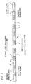
- the tape of a recorded pancake has a number of programmes recorded thereon in sequence.
- the tape includes a short terminal length 1 used for threading the tape of the unrecorded pancake on the recorder.
- An index mark 2 recorded on the tape as an interruption in the video sync track after this length signifies the start of the tape carrying te first recorded programme.
- the following length of tape P is recorded with the programme. This is terminated by a length of tape 3 recorded serially with pulse coded information represented as a sequence of interruptions in the sync track of the video recording.
- a very short length of tape 4 then separates the code signals from another index mark signifying the beginning of the next length of tape recorded with programme material. This very short length is determined by the type of mastering system used in the recording procedure. If a single shuttle master is used, the very short tape length 4 represents the period during which the recorder is paused for the master cassette to rewind. If an alternating master system is employed, length 4 signifies a period inserted into procedures by the control system of the recorder to ensure inter-programme stability.
- sequence index-programme-code-very short length is repeated to the end of the tape (the programmes being the same or different and the codes recorded after each programme representing the details of the programme just recorded, then a final code block 6 at the end of the tape is followed by a short terminal length 5 inserted by the interface computer to allow for handling during winding.
- the length 5 is left at the leading end of the first cassette to be loaded from the recorded pancake reel 18.
- the coded information in the code block 3 and generated by the interface computer 12 is referred to as "global” information.
- the code block 3 also includes "local” information which is provided by the encoder forming part of the recorder 14 on which the particular pancake reel 18 has been recorded.
- the index mark 2 and data 3 are recorded on the tape, as mentioned earlier, as pulses in the form of interruptions in the sync track of the video recording.
- the interruptions are caused by control line pulses of various length output from the interface computer.
- the tape is transported at many times the normal playback speed and it is essential that the signals which convey the coded information can be read with accuracy and consistency: the form of these signals, as will be discussed below, ensures that this can be achieved.
- a magnetic video tape T is recorded with diagonal "stripes" D containing television picture signals comprising raster scan control signals and picture information: even in the so-called "grey" areas at the end of the programme recording the tape has such inclined stripes D containing the television raster scan control signals but no picture information.
- a synchronisation signal S the function of which is to provide a reference signal for the operation of a video playback machine to enable it to compensate for minor variations in the speed at which its motors run in relation to the speed at which the tape was transported during recording. It is this sync track which makes it possible for a video tape to be played back successfully on different playback machines.
- the form of the video sync track is illustrated in more detail with reference to Figure 5.
- the synchronisation signal is recorded by successively applying a magnetising field across the video tape for a very short time period to cause saturation magnetisation first in one direction and then in the other.
- Figure 5 may thus be considered as the form of an electrical signal applied to a recording transducer or one generated by a read transducer, or alternatively as a representation of the magnetisation state of the tape along its length.
- Successive similarly directed peaks K1, K3 etc. are spaced an equal distance apart and the time (when regarded as an electrical signal) or distance (when regarded as magnetisation of the tape) between adjacent peaks represents the time or distance between regularly occurring events.
- the problem which is addressed by the present invention is that the data signals which are to be recorded on the tape as selective interruptions of the synchronising pulse signal Ki occur in an entirely asynchronous manner and must therefore be equally valid and detectable whenever in the synchronisation pulse cycle the data signals should commence, bearing in mind that because the tape is being transported at high speed it is desirable to keep the length of tape occupied by the data code as short as possible.
- Decoding of the coded data is achieved by detecting the sync track of the tape as it is transported at high speed such as for loading and segmenting the encoded signal read from the tape into cells by reference to a stroboscopically generated decode clock signal which is synchronised with the tape movement so that its frequency is always uniquely related to the pulse repetition frequency of the sync track signal pulses Ki. This may be achieved mechanically by means of a stroboscope wheel in the tape transport mechanism or by electrical or electronic means as appropriate.
- the sync track signal pulses Ki may be considered as events which, depending on the encoded signal which suppresses or erases certain pulses, may or may not occur in any given cell in the sequential series of cells into which the signal read from the sync track is segmented for the purpose of decoding. Sequential cells of the same sort (ie containing events or not containing events) are then accumulated in the hardware decoder and interpreted as either a binary 1 or a binary 0 depending on the number of sequential similar cells counted.
- an “include period” is a period, measured in either time or distance (ie as a signal or as a recording on tape) for which the event is allowed to take place to form the code.
- an include 0 period is a short include period, which upon decoding gives rise to a binary 0
- an include 1 is a long include period, which upon decoding gives rise to a binary 1.
- an “exclude period” is a period, again measured in either time or distance, for which the event is inhibited to form the code.
- an “exclude 0" period is a short exclude period which, upon decoding gives rise to a binary 1
- an “exclude 1" period is a long exclude period which, upon decoding gives rise to a binary 1.
- a cell or "length cell” is a period, measured in either time or distance, into which the encoded signal is segmented for decoding, and it is necessary to distinguish between a "full cell” namely a length cell containing an event, and an "empty cell” which is a length cell not containing an event.
- control signal recorded down the edge of the tape which is used as the event, has a different period for PAL from that for NTSC, but calculations may be made for both systems.
- the actual method used depends on the type of tape copying system being used and at what stage the code is being introduced.
- control pulses are prevented from being recorded by shorting out the control track record head to create the exclude periods.
- Control pulses are recorded by passing a DC current through the control track head first in one direction and then in the other. This creates short lengths of magnetic saturation along the tape first in one sense and then the other as described in relation to Figure 5.
- the rapid change in flux during replay creates the control pulse. Shorting out the head leaves the tape unrecorded and the transition from saturated recording in either sense to no recording also creates a flux change in the replay head and thus a pulse. These extra pulses may be seen as an event by the decoder and must be taken into account in the calculations.
- Worst Case Cell Count
- Length The maximum number of full or empty cells created by the Worst case
- the event period must be shorter than the length cell to guarantee that, when examining an include period, an event will be seen. Also both include and exclude 0 and include and exclude 1 must be longer than the Length cell in order that a full or empty cell may be created.
- a 0 may be considered as a minimum of 1 length cell (either full or empty). Since all the possible binary bit generators (include 0, include 1, exclude 0, exclude 1) are asynchronous to both the events and the length cells, more than one full or empty cell may be decoded having encoded a 0. Therefore, a 1 is defined as the minimum number of sequential full or empty cells sufficient to distinguish them from a 0.
- the event period is not relevant in exclude periods. In this worst case an extra full cell is added to the prior full cell count created by the previous include pulse.
- the cell count worst case will occur in an encoding system which does not produce extra events at the beginning and end of an exclusion pulse.
- the exclusion pulse it is possible for the exclusion pulse to occur up to one event period after the beginning of a length cell and the cell still be empty. This means the end of the exclusion poulse occurs at up to one event period after the end of the (EC+1) length cell. If the end of the exclusion pulse occurs just after an event, then a further event period must take place before a full cell is registered. Therefore, if a length cell is less than twice the length of the event period, a further empty cell may occur making a maximum of (EC+2) empty cells.
- the decoder has an event counter which is reset every length cell. Although this reset pulse is short, if it is coincident with an event the result will be indeterminate. Therefore in the "worst case" calculations at least two events must be specified.
- the cell count worst case occurs when the include pulse starts immediately before an event and is followed immediately by a length cell.
- the event included makes the previous cell full. From the worst case (length), it can be seen that the include pulse may extend two event periods beyond the end of the penultimate length cell. This could give rise to a further full cell, that is a total of (FC+2).
- a short pulse (typically in the region of 1 sec) represents binary 0 during serial encoding of global information and a long pulse (typically in the region of 2 secs) represents binary 1 during serial encoding of global information, whilst a very long pulse (typically in the region of 4 secs) represents an index mark.
- Computer-generated short and long pulses are used to make up global information, and also Local Information Clocks (LIC) to which the individual recorders respond by encoding, with similar pulses, the required local information to be recorded onto the tape.
- LIC Local Information Clocks
- Each LIC triggers the recorder to enclode one bit of local information and record it onto the tape, and contains timing information which controls the period of recorder-generated long and short pulses making up the local information codes.
- Global information is output directly from the Interface computer 11 along the control line 20.
- the second control line 21 is held inactive during global output on line 20.
- the global information encoded as described above typically has the following composition.
- Metres Length range - 0-511 Metres Coding method The programme length is converted directly into a 9 bit binary number.
- Coding method The day number is converted into a 5 bit binary number.
- Coding method An equivalent year number is calculated by subtracting 1986 from the actual year. The range is thus reduced to 0-31. This is converted directly to a 5 bit number.
- the global information code sequence is thus as follows:-
- LIC Local Information Clock
- Each LIC pulse is the simultaneous transmission of a long pulse on the main control line 20 used for global output (signifying binary 1) and a short pulse on the second control line 21 from the interface computer 11 (signifying binary 0).
- the leading edges of the pulses must be coincident to a tolerance of ⁇ 5 ms.
- Range of numbers 0-1023 Coding method:- Direct conversion of EVD number to a 10 bit binary number.
- Range of numbers 0-511 Coding method - Direct Conversion to a 9 bit binary number.
- the local information code sequence is thus as follows:-
- a main support panel 31 carries a spindle 32 driven by a drive motor 33 (shown in broken outline in Figure 2). Energisation of the motor 33 causes rotation of the spindle 32 and thus of the pancake reel 18 carried thereon to discharge recorded magnetic tape 7 through a path defined by a series of rollers generally indicated 34, including a capstan 35 to the spindle of which is fixed an optical encoder (not illustrated) in the form of a disc having an annular array of apertures with a light source on one side and a photo detector on the other for encoding the displacement of the tape as it is loaded into a cassette.
- the tape guide rollers 34 guide the tape 7 past a magnetic reed head or transducer 39 which is connected by a line 40 to a decoder 41 having output lines 42 and 43, the first of which leads to a central control panel 44 and the second of which leads to a bar code label printer 45.
- the central control panel 44 has an output line 46 leading to the motor 33 driving the spindle 32 carrying the pancake reel 18, and an output line 47 which controls the displacement of the tape into the loading station 37 and is connected, as mentioned above, to the optical encoder for producing feedback signals representing the actual displacement of the tape.
- the data signals recorded on the tape 7 thus control the operation of the machine loading the tape into the cassette shells and also the printing of bar code labels identifying the programme content and production history of the cassette itself.
- the control unit 44 is operated, via a keyboard, to indicate to the system that a new pancake reel 18 has been placed in position and the capstan motor 48 and main reel drive motor 33 are placed on standby whilst the loader performs the first tape splicing operation, withdrawing a leader tape from the first cassette shell, cutting it, splicing one cut end to the leading end of the magnetic tape 7 and then passing a signal to the control unit 44 to indicate that the first splice has been successfully completed.
- the motors 48 and 33 are then energised, together with a further motor, not illustrated, which drives a spindle on which the hub of the spool within the cassette shell at the loading station is engaged so that magnetic tape 7 is unwound from the pancake reel 18 and wound onto the cassette at the loading station 37 after having passed the rollers 34.
- the transducer 39 As the first code block 6 on the magnetic tape 7 passes the transducer 39 this reads the signals represented thereby and passes them along the line 40 to the decoder 41 which decodes the relevant sections and passes signals along the line 42 to the control unit 44 indicating the length of the programme recorded on the tape being wound into the cassette.
- the controller 44 compares this information with data coming from the encoder linked to the capstan 35 and, a predetermined time (or rather a predetermined distance) before the end of the programme starts to decelerate both the main reel drive motor 33 and the capstan 35 ready for the arrival of the first index mark 4 which will signify the end of the programme and, upon arrival, will cause the control unit 44 to stop the motors and initiate a tape splicing operation for cutting the tape at a point between the index mark 4 and the next code block 6 along the tape.
- the label printer 45 which is thus energised to print a bar code label representing the data read from the tape.
- the label after printing, is automatically passed to a label applicator 51 positioned closely adjacent the loading station 37, and is triggered to apply the label to the cassette shell either during loading of the tape 7 bearing the programme identified by the label just printed, or immediately after loading has been completed as the filled casssette is transferred from the loading station 37 to the discharge rack 38.
- the transducer 39 Since the short length of blank tape between each index mark 4 and code block 6 is very short the transducer 39 will, in practice, read the subsequent code block 6 immediately after the index mark 4 and the data represented thereby will be decoded by the decoder 41 and stored in the short term buffer memory of the control unit 44 so that the necessary information for control of the next tape loading operation is already present immediately the confirmation signals from the tape splicing unit 50 and the labelled applicator 51 are received to allow the motors 33 and 48 to be re-energised to commence the next loading cycle.
- Loaded cassettes bearing the bar code label identifying the tape recording on the magnetic tape contained in the cassette shell are then removed from the discharge rack 38 and fed to a sort line where the bar code labels can be automatically read and the cassettes directed to label applicator stations at which printed labels identifying the programme and containing, for example, advertising and other normal label material can be applied.
- the apparatus of the present invention also allows recordings to be made on a speculative basis since the data concerning the programme material recorded on a pancake reel 18 is carried on the tape itself and it is possible to keep the recorders operating fulltime recording those programmes which it is anticipated will be in demand.
- the pancake reels 18 can be stored without being put into cassettes and withdrawn from store and loaded into cassettes when demand requires. If the demand for any particular programme material does not arise it is a simple matter magnetically to wipe the recording from the page 7 and rerecord a new programme, something which is not convenient once the tape has been loaded into a cassette since this would require individual cassette recorders and, almost inevitably, either expensive automatic cassette recorder loading equipment or even more expensive labour.
- data recorded on tape may be recorded as ordered magnetic domains or as randomised magnetic domains (eg an interruption in a control signal) and the expression "recorded” as used herein should be construed accordingly.
- the data will in general be provided by the interfaced computer linked to signal recording means but could merely be data recorded after completing the programme material recording of a pancake, for example, data encoded on the tape by winding machine and representing any one or more of the identity of the winding machine, the date of winding, cassette or cassette batch identity and/or any one or more items of other information.
Landscapes
- Indexing, Searching, Synchronizing, And The Amount Of Synchronization Travel Of Record Carriers (AREA)
- Controlling Rewinding, Feeding, Winding, Or Abnormalities Of Webs (AREA)
- Management Or Editing Of Information On Record Carriers (AREA)
Priority Applications (1)
| Application Number | Priority Date | Filing Date | Title |
|---|---|---|---|
| AT88300752T ATE99447T1 (de) | 1987-01-29 | 1988-01-28 | Herstellung voraufgezeichneter bandkassetten. |
Applications Claiming Priority (8)
| Application Number | Priority Date | Filing Date | Title |
|---|---|---|---|
| GB8701983 | 1987-01-29 | ||
| GB878701983A GB8701983D0 (en) | 1987-01-29 | 1987-01-29 | Pre-recorded tape cassettes |
| GB8721314 | 1987-09-10 | ||
| GB878721314A GB8721314D0 (en) | 1987-09-10 | 1987-09-10 | Pre-recorded cassettes |
| GB8727275 | 1987-11-20 | ||
| GB8727275A GB2200787B (en) | 1987-01-29 | 1987-11-20 | Improved production of pre-recorded tape casssettes. |
| GB8730168 | 1987-12-24 | ||
| GB878730168A GB8730168D0 (en) | 1987-12-24 | 1987-12-24 | Encoding system |
Related Child Applications (1)
| Application Number | Title | Priority Date | Filing Date |
|---|---|---|---|
| EP91120651.4 Division-Into | 1991-12-01 |
Publications (3)
| Publication Number | Publication Date |
|---|---|
| EP0277778A2 true EP0277778A2 (fr) | 1988-08-10 |
| EP0277778A3 EP0277778A3 (en) | 1988-10-12 |
| EP0277778B1 EP0277778B1 (fr) | 1993-12-29 |
Family
ID=27449875
Family Applications (1)
| Application Number | Title | Priority Date | Filing Date |
|---|---|---|---|
| EP88300752A Expired - Lifetime EP0277778B1 (fr) | 1987-01-29 | 1988-01-28 | Production de cassettes à bandes préenregistrées |
Country Status (8)
| Country | Link |
|---|---|
| US (1) | US5148403A (fr) |
| EP (1) | EP0277778B1 (fr) |
| JP (1) | JPH07114036B2 (fr) |
| AU (1) | AU1185888A (fr) |
| CA (1) | CA1336205C (fr) |
| DE (1) | DE3886556T2 (fr) |
| ES (1) | ES2047025T3 (fr) |
| WO (1) | WO1988005955A2 (fr) |
Cited By (4)
| Publication number | Priority date | Publication date | Assignee | Title |
|---|---|---|---|---|
| EP0496461A1 (fr) * | 1991-01-25 | 1992-07-29 | Koninklijke Philips Electronics N.V. | Cassette pourvue d'une bande magnétique et procédé de fabrication de la cassette |
| EP0430717A3 (en) * | 1989-12-01 | 1993-08-18 | Sony Magnescale Inc. | Improvements in, or relating to tape duplicator systems |
| WO1997001845A1 (fr) * | 1995-06-29 | 1997-01-16 | Eastman Kodak Company | Procede et dispositif pour preparer l'etiquetage de disques numeriques |
| US6109324A (en) * | 1996-06-17 | 2000-08-29 | Eastman Kodak Company | Method and apparatus for preparing labelled digital disc |
Families Citing this family (21)
| Publication number | Priority date | Publication date | Assignee | Title |
|---|---|---|---|---|
| JP2949747B2 (ja) * | 1990-01-21 | 1999-09-20 | ソニー株式会社 | 情報入力装置 |
| US6091884A (en) * | 1991-08-19 | 2000-07-18 | Index Systems, Inc. | Enhancing operations of video tape cassette players |
| US5621579A (en) * | 1991-08-19 | 1997-04-15 | Index Systems, Inc. | Method for selectively playing back programs recorded on a video tape |
| US6487362B1 (en) | 1991-08-19 | 2002-11-26 | Index Systems, Inc. | Enhancing operations of video tape cassette players |
| US6240241B1 (en) | 1991-08-19 | 2001-05-29 | Index Systems, Inc. | Still frame video in index |
| US5724203A (en) * | 1991-08-19 | 1998-03-03 | Index Systems, Inc. | Method and apparatus for determining addresses in time along a recording tape |
| ATE179274T1 (de) * | 1992-02-28 | 1999-05-15 | E Systems Inc | Systembereiche für bandladeoperationen |
| US5383733A (en) * | 1992-07-24 | 1995-01-24 | Summagraphics Corporation | Ribbon cassette for a printer |
| US5543929A (en) * | 1993-01-05 | 1996-08-06 | E. Guide, Inc. | Television for controlling a video cassette recorder to access programs on a video cassette tape |
| WO1994017523A1 (fr) * | 1993-01-25 | 1994-08-04 | Schwab Barry H | Duplicateur de bande magnetique et chargeur de cassettes combines |
| US5420742A (en) * | 1993-07-30 | 1995-05-30 | Minnesota Mining And Manufacturing | Degausser for tape with plural recorded segments |
| US5518325A (en) * | 1994-02-28 | 1996-05-21 | Compulog | Disk label printing |
| US5611066A (en) * | 1994-02-28 | 1997-03-11 | Data/Ware Development, Inc. | System for creating related sets via once caching common file with each unique control file associated within the set to create a unique record image |
| US5721655A (en) * | 1996-07-15 | 1998-02-24 | Electronic Data Systems Corporation | Method for labeling a removable media cartridge |
| US6246655B1 (en) | 1996-10-17 | 2001-06-12 | David Miller | Programmable self-operating caddy-loaded compact disk duplication system |
| US6074031A (en) * | 1997-12-11 | 2000-06-13 | Compulog Corporation | Method and apparatus for printing labels on digital recording media |
| US6270176B1 (en) | 1997-12-11 | 2001-08-07 | Compulog Corporation | Method and apparatus for printing labels on digital recording media |
| AU2001286048A1 (en) | 2000-09-11 | 2002-03-26 | Zipher Limited | Tape drive and printing apparatus |
| JP2004152354A (ja) * | 2002-10-29 | 2004-05-27 | Fuji Photo Film Co Ltd | カートリッジメモリ読取・書込装置 |
| US8270303B2 (en) | 2007-12-21 | 2012-09-18 | Hand Held Products, Inc. | Using metadata tags in video recordings produced by portable encoded information reading terminals |
| US20100198876A1 (en) | 2009-02-02 | 2010-08-05 | Honeywell International, Inc. | Apparatus and method of embedding meta-data in a captured image |
Family Cites Families (28)
| Publication number | Priority date | Publication date | Assignee | Title |
|---|---|---|---|---|
| US2976372A (en) * | 1959-03-02 | 1961-03-21 | Sidney O Sampson | Magnetic tape reproducing system |
| US3072753A (en) * | 1959-11-27 | 1963-01-08 | Minnesota Mining & Mfg | Apparatus for duplicating magnetic recordings |
| FR78218E (fr) * | 1960-08-02 | 1962-06-22 | Heurtey & Cie | Procédé de recouvrement de fils métalliques par une ou plusieurs couches de métaux fondus |
| US3298006A (en) * | 1962-12-19 | 1967-01-10 | American Mach & Foundry | Tape transcriber and transport mechanism therefor |
| GB1321977A (en) * | 1971-03-10 | 1973-07-04 | Feinpruef Feinmess Und Pruefge | Continuous laminar mixer for highly viscous media |
| JPS5228654B2 (fr) * | 1972-11-20 | 1977-07-28 | ||
| US3827077A (en) * | 1973-02-20 | 1974-07-30 | Minnesota Mining & Mfg | Two-stage contact duplication of magnetic signals utilizing a metal-backed intermediate |
| US4185305A (en) * | 1974-03-04 | 1980-01-22 | Bell & Howell Company | Video information recording and reproducing methods and apparatus |
| JPS5353916A (en) * | 1976-10-27 | 1978-05-16 | Sony Corp | Recording unit for video signal |
| US4113196A (en) * | 1976-11-04 | 1978-09-12 | Electro-Sound, Inc. | Magnetic tape cartridge loading apparatus |
| DE2837598A1 (de) * | 1977-09-10 | 1979-03-22 | Ii Peter Copeland | Steuereinrichtung |
| JPS6047652B2 (ja) * | 1978-02-10 | 1985-10-23 | ソニー株式会社 | カ−ド貼着する磁気テ−プの記録方法 |
| JPS6048811B2 (ja) * | 1979-02-09 | 1985-10-29 | 三菱電機株式会社 | 磁気記録再生装置 |
| US4261021A (en) * | 1979-04-16 | 1981-04-07 | Lanier Business Products, Inc. | Cassette labeling apparatus |
| US4377111A (en) * | 1979-11-28 | 1983-03-22 | King Instrument Corporation | Cassette stacking device |
| FR2515403A1 (fr) * | 1981-10-28 | 1983-04-29 | Quadrivium Inf | Procede d'identification d'un enregistrement sonore et installation de duplication mettant en oeuvre le procede |
| JPS58171726A (ja) * | 1982-04-02 | 1983-10-08 | Victor Co Of Japan Ltd | 磁気テ−プのダビング装置 |
| JPS58224485A (ja) * | 1982-06-23 | 1983-12-26 | Toshiba Corp | ビデオテ−プレコ−ダの情報記録再生装置 |
| DE3309029C2 (de) * | 1983-03-14 | 1985-05-15 | Winfried Dipl.-Ing.(FH) 8000 München Walter | Verfahren zum Bestimmen der momentanen Bandlänge eines Videomagnetbandes und nach diesem Verfahren bespielte Videomagnetbänder |
| JPS59215087A (ja) * | 1983-05-20 | 1984-12-04 | Hitachi Ltd | 記録内容表示方式 |
| JPS6025062A (ja) * | 1983-07-21 | 1985-02-07 | Sony Corp | 番地信号の記録方法 |
| JPS6093692A (ja) * | 1983-10-25 | 1985-05-25 | Dainippon Printing Co Ltd | コンピユ−タ用プログラムテ−プの複製方法及び装置 |
| JPS60109044A (ja) * | 1983-11-17 | 1985-06-14 | Pioneer Electronic Corp | 曲間検出方式 |
| DE3504354A1 (de) * | 1984-02-10 | 1985-08-22 | Pioneer Electronic Corp., Tokio/Tokyo | Bandpositionsdaten-aufzeichnungs- und -wiedergabeverfahren |
| DE3405910C1 (de) * | 1984-02-18 | 1985-12-12 | Christian 8521 Effeltrich Ebeling | Verfahren zur Steuerung eines Videobandgeraetes zum automatischen Auffinden von bespielten Videobandabschnitten sowie Videobandgeraet zur Durchfuehrung des Verfahrens |
| JPS60253023A (ja) * | 1984-05-29 | 1985-12-13 | Sony Corp | 磁気転写装置 |
| US4663678A (en) * | 1984-06-18 | 1987-05-05 | Odetics, Inc. | System for writing and reading digital data interspersed with analog audio frequency data on magnetic recording tape |
| JPS61187183A (ja) * | 1985-02-15 | 1986-08-20 | Sony Corp | 記録方式 |
-
1988
- 1988-01-28 ES ES88300752T patent/ES2047025T3/es not_active Expired - Lifetime
- 1988-01-28 WO PCT/GB1988/000051 patent/WO1988005955A2/fr not_active Ceased
- 1988-01-28 DE DE88300752T patent/DE3886556T2/de not_active Expired - Fee Related
- 1988-01-28 JP JP63501237A patent/JPH07114036B2/ja not_active Expired - Lifetime
- 1988-01-28 EP EP88300752A patent/EP0277778B1/fr not_active Expired - Lifetime
- 1988-01-28 AU AU11858/88A patent/AU1185888A/en not_active Abandoned
- 1988-01-29 CA CA000557687A patent/CA1336205C/fr not_active Expired - Fee Related
-
1991
- 1991-07-16 US US07/731,290 patent/US5148403A/en not_active Expired - Fee Related
Cited By (4)
| Publication number | Priority date | Publication date | Assignee | Title |
|---|---|---|---|---|
| EP0430717A3 (en) * | 1989-12-01 | 1993-08-18 | Sony Magnescale Inc. | Improvements in, or relating to tape duplicator systems |
| EP0496461A1 (fr) * | 1991-01-25 | 1992-07-29 | Koninklijke Philips Electronics N.V. | Cassette pourvue d'une bande magnétique et procédé de fabrication de la cassette |
| WO1997001845A1 (fr) * | 1995-06-29 | 1997-01-16 | Eastman Kodak Company | Procede et dispositif pour preparer l'etiquetage de disques numeriques |
| US6109324A (en) * | 1996-06-17 | 2000-08-29 | Eastman Kodak Company | Method and apparatus for preparing labelled digital disc |
Also Published As
| Publication number | Publication date |
|---|---|
| AU1185888A (en) | 1988-08-24 |
| DE3886556D1 (de) | 1994-02-10 |
| ES2047025T3 (es) | 1994-02-16 |
| CA1336205C (fr) | 1995-07-04 |
| US5148403A (en) | 1992-09-15 |
| JPH07114036B2 (ja) | 1995-12-06 |
| WO1988005955A3 (fr) | 1988-09-07 |
| JPH01502703A (ja) | 1989-09-14 |
| EP0277778A3 (en) | 1988-10-12 |
| WO1988005955A2 (fr) | 1988-08-11 |
| EP0277778B1 (fr) | 1993-12-29 |
| DE3886556T2 (de) | 1994-04-21 |
Similar Documents
| Publication | Publication Date | Title |
|---|---|---|
| US5148403A (en) | Production of prerecorded tape cassettes | |
| US3950782A (en) | Data storage and retrieval systems for use with plural track storage medium | |
| US3721757A (en) | Method and apparatus for automatically editing television information | |
| GB2122799A (en) | Improvements in or relating to video tape players and pre-recorded cassettes therefor | |
| US3812532A (en) | Random access memory with tape return to a midtape reference position after reading | |
| GB2131996A (en) | Data storage devices | |
| EP0628197B1 (fr) | Format de piste asservie numerique | |
| US5543977A (en) | Data recording system having improved longitudinal and helical search capability | |
| EP0628196B1 (fr) | Systeme d'enregistrement de donnees comprenant des indicateurs de format de fin d'enregistrement et de debut d'enregistrement | |
| EP0476725A2 (fr) | Production de bande préenregistrée et cassettes à bandes | |
| EP0437219B1 (fr) | Appareil de reproduction avec balayage hélicoidal pour données numériques | |
| GB2200493A (en) | Method and apparatus for recording and loading tape cassette | |
| US5319504A (en) | Method and apparatus for marking a data block defective and re-recording data block in successive regions | |
| GB2200787A (en) | Method and apparatus for recording and loading tape cassette | |
| WO1993017432A1 (fr) | Format de piste longitudinal pour systeme d'enregistrement de donnees | |
| US5341378A (en) | Data recording system having improved automatic rewrite capability and method of rewriting | |
| EP0504973A1 (fr) | Dispositif de lecture d'une plage d'un support d'enregistrement magnétique (position de bande préférée) | |
| US6240242B1 (en) | Recording apparatus for recording moving image and still image | |
| JP2626000B2 (ja) | 記録再生装置 | |
| US5570014A (en) | Method and apparatus for testing the position of a point on edited magnetic tapes packed in cassettes via a cuetone | |
| JP3102071B2 (ja) | ビデオテープレコーダ | |
| EP0639828A1 (fr) | Appareil d'enregistrement/reproduction d'informations magnétiques et milieu magnétique pour l'utilisation avec celui-ci | |
| JPH0156467B2 (fr) | ||
| JPH0740383B2 (ja) | 磁気テープの検査装置 | |
| JPS58171725A (ja) | 磁気テ−プのダビング方法 |
Legal Events
| Date | Code | Title | Description |
|---|---|---|---|
| PUAI | Public reference made under article 153(3) epc to a published international application that has entered the european phase |
Free format text: ORIGINAL CODE: 0009012 |
|
| AK | Designated contracting states |
Kind code of ref document: A2 Designated state(s): AT BE CH DE ES FR GB GR IT LI LU NL SE |
|
| PUAL | Search report despatched |
Free format text: ORIGINAL CODE: 0009013 |
|
| AK | Designated contracting states |
Kind code of ref document: A3 Designated state(s): AT BE CH DE ES FR GB GR IT LI LU NL SE |
|
| 17P | Request for examination filed |
Effective date: 19890412 |
|
| 17Q | First examination report despatched |
Effective date: 19901123 |
|
| RAP1 | Party data changed (applicant data changed or rights of an application transferred) |
Owner name: SONY MAGNESCALE, INC. |
|
| GRAA | (expected) grant |
Free format text: ORIGINAL CODE: 0009210 |
|
| AK | Designated contracting states |
Kind code of ref document: B1 Designated state(s): AT BE CH DE ES FR GB GR IT LI LU NL SE |
|
| PG25 | Lapsed in a contracting state [announced via postgrant information from national office to epo] |
Ref country code: SE Effective date: 19931229 Ref country code: LI Effective date: 19931229 Ref country code: GR Free format text: LAPSE BECAUSE OF FAILURE TO SUBMIT A TRANSLATION OF THE DESCRIPTION OR TO PAY THE FEE WITHIN THE PRESCRIBED TIME-LIMIT Effective date: 19931229 Ref country code: CH Effective date: 19931229 Ref country code: BE Effective date: 19931229 Ref country code: AT Effective date: 19931229 |
|
| REF | Corresponds to: |
Ref document number: 99447 Country of ref document: AT Date of ref document: 19940115 Kind code of ref document: T |
|
| PG25 | Lapsed in a contracting state [announced via postgrant information from national office to epo] |
Ref country code: LU Free format text: LAPSE BECAUSE OF NON-PAYMENT OF DUE FEES Effective date: 19940131 |
|
| REF | Corresponds to: |
Ref document number: 3886556 Country of ref document: DE Date of ref document: 19940210 |
|
| REG | Reference to a national code |
Ref country code: ES Ref legal event code: FG2A Ref document number: 2047025 Country of ref document: ES Kind code of ref document: T3 |
|
| ET | Fr: translation filed | ||
| ITF | It: translation for a ep patent filed | ||
| REG | Reference to a national code |
Ref country code: CH Ref legal event code: PL |
|
| PLBE | No opposition filed within time limit |
Free format text: ORIGINAL CODE: 0009261 |
|
| STAA | Information on the status of an ep patent application or granted ep patent |
Free format text: STATUS: NO OPPOSITION FILED WITHIN TIME LIMIT |
|
| 26N | No opposition filed | ||
| PGFP | Annual fee paid to national office [announced via postgrant information from national office to epo] |
Ref country code: GB Payment date: 19981209 Year of fee payment: 12 |
|
| PGFP | Annual fee paid to national office [announced via postgrant information from national office to epo] |
Ref country code: FR Payment date: 19981217 Year of fee payment: 12 |
|
| PGFP | Annual fee paid to national office [announced via postgrant information from national office to epo] |
Ref country code: ES Payment date: 19990104 Year of fee payment: 12 |
|
| PGFP | Annual fee paid to national office [announced via postgrant information from national office to epo] |
Ref country code: DE Payment date: 19990108 Year of fee payment: 12 |
|
| PGFP | Annual fee paid to national office [announced via postgrant information from national office to epo] |
Ref country code: NL Payment date: 19990129 Year of fee payment: 12 |
|
| PG25 | Lapsed in a contracting state [announced via postgrant information from national office to epo] |
Ref country code: GB Free format text: LAPSE BECAUSE OF NON-PAYMENT OF DUE FEES Effective date: 20000128 |
|
| PG25 | Lapsed in a contracting state [announced via postgrant information from national office to epo] |
Ref country code: ES Free format text: LAPSE BECAUSE OF NON-PAYMENT OF DUE FEES Effective date: 20000129 |
|
| PG25 | Lapsed in a contracting state [announced via postgrant information from national office to epo] |
Ref country code: NL Free format text: LAPSE BECAUSE OF NON-PAYMENT OF DUE FEES Effective date: 20000801 |
|
| GBPC | Gb: european patent ceased through non-payment of renewal fee |
Effective date: 20000128 |
|
| PG25 | Lapsed in a contracting state [announced via postgrant information from national office to epo] |
Ref country code: FR Free format text: LAPSE BECAUSE OF NON-PAYMENT OF DUE FEES Effective date: 20000929 |
|
| NLV4 | Nl: lapsed or anulled due to non-payment of the annual fee |
Effective date: 20000801 |
|
| PG25 | Lapsed in a contracting state [announced via postgrant information from national office to epo] |
Ref country code: DE Free format text: LAPSE BECAUSE OF NON-PAYMENT OF DUE FEES Effective date: 20001101 |
|
| REG | Reference to a national code |
Ref country code: FR Ref legal event code: ST |
|
| REG | Reference to a national code |
Ref country code: ES Ref legal event code: FD2A Effective date: 20010910 |
|
| PG25 | Lapsed in a contracting state [announced via postgrant information from national office to epo] |
Ref country code: IT Free format text: LAPSE BECAUSE OF NON-PAYMENT OF DUE FEES;WARNING: LAPSES OF ITALIAN PATENTS WITH EFFECTIVE DATE BEFORE 2007 MAY HAVE OCCURRED AT ANY TIME BEFORE 2007. THE CORRECT EFFECTIVE DATE MAY BE DIFFERENT FROM THE ONE RECORDED. Effective date: 20050128 |