EP0277953B1 - Förderanordnung von luft - Google Patents
Förderanordnung von luft Download PDFInfo
- Publication number
- EP0277953B1 EP0277953B1 EP87900312A EP87900312A EP0277953B1 EP 0277953 B1 EP0277953 B1 EP 0277953B1 EP 87900312 A EP87900312 A EP 87900312A EP 87900312 A EP87900312 A EP 87900312A EP 0277953 B1 EP0277953 B1 EP 0277953B1
- Authority
- EP
- European Patent Office
- Prior art keywords
- electrode
- corona
- wire
- corona electrode
- target
- Prior art date
- Legal status (The legal status is an assumption and is not a legal conclusion. Google has not performed a legal analysis and makes no representation as to the accuracy of the status listed.)
- Expired
Links
- 230000002093 peripheral effect Effects 0.000 claims abstract description 12
- 150000002500 ions Chemical class 0.000 claims description 16
- 230000005684 electric field Effects 0.000 claims description 4
- 238000011144 upstream manufacturing Methods 0.000 description 9
- IJGRMHOSHXDMSA-UHFFFAOYSA-N Atomic nitrogen Chemical compound N#N IJGRMHOSHXDMSA-UHFFFAOYSA-N 0.000 description 4
- 238000010276 construction Methods 0.000 description 4
- 238000012216 screening Methods 0.000 description 4
- CBENFWSGALASAD-UHFFFAOYSA-N Ozone Chemical compound [O-][O+]=O CBENFWSGALASAD-UHFFFAOYSA-N 0.000 description 3
- 238000004519 manufacturing process Methods 0.000 description 2
- 230000007935 neutral effect Effects 0.000 description 2
- 229910052757 nitrogen Inorganic materials 0.000 description 2
- 239000002341 toxic gas Substances 0.000 description 2
- 239000000443 aerosol Substances 0.000 description 1
- 230000015572 biosynthetic process Effects 0.000 description 1
- 239000004020 conductor Substances 0.000 description 1
- 238000011161 development Methods 0.000 description 1
- 230000018109 developmental process Effects 0.000 description 1
- 239000012777 electrically insulating material Substances 0.000 description 1
- 239000012799 electrically-conductive coating Substances 0.000 description 1
- 239000007788 liquid Substances 0.000 description 1
- 239000000463 material Substances 0.000 description 1
- 239000002245 particle Substances 0.000 description 1
- 230000005855 radiation Effects 0.000 description 1
- 239000007787 solid Substances 0.000 description 1
- 239000000725 suspension Substances 0.000 description 1
Images

Classifications
-
- H—ELECTRICITY
- H01—ELECTRIC ELEMENTS
- H01T—SPARK GAPS; OVERVOLTAGE ARRESTERS USING SPARK GAPS; SPARKING PLUGS; CORONA DEVICES; GENERATING IONS TO BE INTRODUCED INTO NON-ENCLOSED GASES
- H01T23/00—Apparatus for generating ions to be introduced into non-enclosed gases, e.g. into the atmosphere
-
- H—ELECTRICITY
- H01—ELECTRIC ELEMENTS
- H01T—SPARK GAPS; OVERVOLTAGE ARRESTERS USING SPARK GAPS; SPARKING PLUGS; CORONA DEVICES; GENERATING IONS TO BE INTRODUCED INTO NON-ENCLOSED GASES
- H01T19/00—Devices providing for corona discharge
-
- Y—GENERAL TAGGING OF NEW TECHNOLOGICAL DEVELOPMENTS; GENERAL TAGGING OF CROSS-SECTIONAL TECHNOLOGIES SPANNING OVER SEVERAL SECTIONS OF THE IPC; TECHNICAL SUBJECTS COVERED BY FORMER USPC CROSS-REFERENCE ART COLLECTIONS [XRACs] AND DIGESTS
- Y10—TECHNICAL SUBJECTS COVERED BY FORMER USPC
- Y10S—TECHNICAL SUBJECTS COVERED BY FORMER USPC CROSS-REFERENCE ART COLLECTIONS [XRACs] AND DIGESTS
- Y10S261/00—Gas and liquid contact apparatus
- Y10S261/42—Ozonizers
-
- Y—GENERAL TAGGING OF NEW TECHNOLOGICAL DEVELOPMENTS; GENERAL TAGGING OF CROSS-SECTIONAL TECHNOLOGIES SPANNING OVER SEVERAL SECTIONS OF THE IPC; TECHNICAL SUBJECTS COVERED BY FORMER USPC CROSS-REFERENCE ART COLLECTIONS [XRACs] AND DIGESTS
- Y10—TECHNICAL SUBJECTS COVERED BY FORMER USPC
- Y10S—TECHNICAL SUBJECTS COVERED BY FORMER USPC CROSS-REFERENCE ART COLLECTIONS [XRACs] AND DIGESTS
- Y10S430/00—Radiation imagery chemistry: process, composition, or product thereof
- Y10S430/138—Corona discharge process
Definitions
- the present invention relates to an arrangement for transporting air with the aid of a so-called ion wind or corona wind and being of the kind set forth in the pre-characterizing clause of Claim 1.
- a common feature of all of the aforesaid arrangements is that a corona electrode and a target electrode are arranged spaced from one another in the desired direction of air flow, the corona electrode and the target electrode both being constructed so that air can pass therethrough.
- the target electrode is placed downstream of the corona electrode, as seen in the direction of airflow, and a source of d.c. voltage is connected between the corona and target electrodes, the voltage of the d.c. voltage source and the construction of the corona electrode being such as to create at the corona electrode a corona discharge which will produce air ions.
- the electrodes are arranged within the confines of an airflow duct, although when such an arrangement is constructed in accordance with our aforesaid international application the provision of such a duct is not an unavoidable necessity, as is made clear in the aforesaid international application.
- corona electrodes hitherto proposed for use with air transporting arrangements of this kind can be divided into two main categories, namely a first category in which the corona electrode comprises an elongated, substantially wire-like corona element which is intended to extend across the airflow path, and a second category in which the corona electrode comprises pointed corona elements, for example corona elements in the form of short, thin wires or needle-like devices which extend axially in the airflow path, with one end of the element secured in a holder and the other, pointed end, which is unattached, being directed towards the target electrode.
- first category in which the corona electrode comprises an elongated, substantially wire-like corona element which is intended to extend across the airflow path
- pointed corona elements for example corona elements in the form of short, thin wires or needle-like devices which extend axially in the airflow path, with one end of the element secured in a holder and the other, pointed end, which is unattached, being directed towards the target
- corona discharge created at said electrode gives rise to the greatest possible transportation of air.
- the corona discharge is stable and creates but the smallest possible amount of toxic gases, primarily ozone and oxides of nitrogen.
- the object of the present invention is to provide an air transporting arrangement of the aforementioned kind having a corona electrode so constructed as to fulfil the aforementioned requirements more fully than do the corona electrodes hitherto proposed for use in such arrangements.
- the invention is based on the experimental discovery that, when compared with an elongated, wire-like corona electrode that extends transversely across the entire cross-section of the airflow path, the transportation of air can be greatly improved when the corona electrode is constructed and arranged in a manner such as to confine the corona discharge to a minor, central part of the cross-section of the airflow path. This is particularly applicable with airflow paths of, for example, circular cross-section or similarly shaped cross-sections.
- a corona electrode that incorporates at least one substantially wire-like electrode element which is arranged adjacent the symmetry axis of that part of the airflow path in which the corona electrode is to provide for the supply of air ions, and which is so constructed and orientated that its extension in a direction perpendicular to said symmetry axis is essentially much smaller than the dimensions of the cross-sectional area of said part of the airflow path, and in which corona electrode the wire-like corona element is so formed and arranged that it lacks ends at which the field strength exceeds the field strength at the peripheral surface of the electrode element and at which punctiform corona discharges could possibly occur, whereby the corona discharge is confined to the peripheral surface of electrode element.
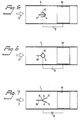
- FIG. 1-7 illustrate schematically a number of mutually different embodiments of an air transporting arrangement constructed in accordance with the invention.
- FIG. 1 illustrates schematically a first embodiment of an air transporting arrangement according to the invention which comprises airflow duct 1, the desired direction of airflow of which is indicated by an arrow 2 and which has a corona electrode K and a target electrode M arranged therein.
- the corona electrode K and the target electrode M are each connected to a respective terminal of a d.c. voltage source 3.
- the airflow duct 1 is of tubular construction, with a circular or like cross-sectional shape, the target electrode M having the form of a cylinder of corresponding shape to the airflow duct 1 and, in the illustrated embodiment, being located closely adjacent the wall of the airflow duct 1 or having the form of an electrically conductive coating applied directly to the inner surface of said wall.
- the arrangement operates in the same manner as the arrangement described in the aforementioned contemporary international patent application, i.e. a corona discharge is created at the corona electrode K and gives rise to air ions which, under the influence of the electric field, migrate from the corona electrode K to the target electrode M, thereby giving rise to the desired flow of air in the duct 1.
- the corona electrode K of the embodiment illustrated in Figure 1 comprises a substantially rectilinear wire 4 of electrically conductive material, the wire being positioned axially in the airflow duct 1 and preferably located along the symmetry axis of said duct.
- the upstream end of the wire-like electrode element 4 is attached to a holder H, which is carried in a suitable manner (not shown) in the airflow duct 1, while the downstream end of the electrode element 4 directed towards the target electrode M is provided with a bulbous body, or droplet-like body 5, which may comprise an electrically conductive or electrically insulating material and which has a substantially larger diameter than the diameter of the wire 4.
- This body 5 prevents the occurrence of a field concentration and therewith a concentration of the corona discharge on the end of the wire-like corona element 4 facing towards the target electrode M. Instead, there is obtained a corona discharge which is spread over the peripheral surface of the electrode element 4 in the manner desired, in the central part of the cross-sectional area of the airflow duct 1, so as to eliminate the disadvantages encountered with the pointed or needle-like corona electrodes hitherto proposed.
- FIG 2 illustrates another embodiment of the invention, in which the corona electrode K comprises a wire-like corona element 4 which although arranged in a similar manner to the corona electrode of the Figure 1 embodiment has both ends attached to respective electrode holders H1 and H2. Because the wire-like electrode element 4 of this embodiment has no free ends, i.e. both ends are attached, the concentration of punctiform corona discharges are effectively avoided, and the corona discharge occurs instead over the peripheral surface of the electrode element 4 in the manner desired.
- the corona electrode K comprises a wire-like corona element 4 which although arranged in a similar manner to the corona electrode of the Figure 1 embodiment has both ends attached to respective electrode holders H1 and H2. Because the wire-like electrode element 4 of this embodiment has no free ends, i.e. both ends are attached, the concentration of punctiform corona discharges are effectively avoided, and the corona discharge occurs instead over the peripheral surface of the electrode element 4 in the manner desired.
- the downstream end of the wire-like electrode element 4 of the corona element K facing towards the target electrode M is surrounded by a tube or sleeve 6, which is operative in screening the end of the electrode wire so that no field concentration, and thus no concentrated corona discharge, can occur on said end of the electrode wire 4.
- This screening of the end of the electrode wire 4 can also be achieved with screening elements having a configuration different to the tube 6.
- corona electrodes K constructed in the manner illustrated by way of example in Figures 1 and 3 can, in principle, be reversed to no disadvantage, so that the holder H of the electrode wire 4 is located downstream, i.e. nearest the target electrode M, while the end of the electrode wire 4 provided with the terminal body 5 or the screening element 6 faces upstream, i.e. away from the target electrode M.
- the corona electrode may conceivably be given the form illustrated by way of example in Figure 4, in accordance with the invention.
- the corona electrode K also comprises a wire-like electrode element 4, the downstream end of which facing towards the target electrode M is secured in a holder H, while the free, unattached end of the wire 4 faces upstream, away from the target electrode M.
- the risk of a punctiform corona discharge concentration at this free end of the electrode wire 4 is very small.
- a terminal body of greater diameter than the diameter of the electrode wire 4 can be provided on the upstream facing end of the electrode wire 4.
- the corona electrode K comprises a substantially U-shaped, thin electrode wire 4, which is attached to a holder H in a manner such as to leave both ends of the electrode unattached, these ends being directed upstream, away from the target electrode M. If desired, these free ends of the electrode wire 4 may be provided with terminal bodies in the aforedescribed manner.
- the corona electrode K comprises a wire-like electrode element 4 which has the shape of a ring or a loop and which is attached to a holder H. Since both ends of the wire-like electrode 4 of this embodiment are held attached, no concentrated or punctiform corona discharges can take place.
- the ring-shaped or loop-shaped electrode element can also be orientated in a plane extending perpendicular to the longitudinal axis of the airflow duct 1.
- a corona electrode according to the invention may also comprise a plurality of electrode elements, for example in the manner illustrated schematically in Figure 7.
- the corona electrode K of the Figure 7 embodiment comprises two or more wire-like electrode elements 4 which are attached at one end thereof to the holder H and which are arranged around the peripheral surface of an imaginary symmetrical cone, the symmetry axis of which coincides with the axis of the airflow duct 1.
- the ends of the wire-like electrode elements 4 facing towards the target electrode M are provided with terminal bodies 5, in a manner similar to the embodiment illustrated in Figure 1, which prevent concentrated corona discharges on the ends of the electrode wires 4.
- the top angle of the imaginary cone, around the peripheral surface of which the electrode wires 4 are arranged, can be varied and in the extreme case may be as large as 180°, such that the electrode wires 4 lie in one and the same plane at right angles to the longitudinal axis of the airflow duct 1.
- corona electrode K illustrated in Figure 7 can also be reversed, so that the unattached ends of the electrode wires 4 are directed upstream, away from the target electrode M, in which case the terminal bodies 5 may optionally be omitted without risk of concentrated, punctiform corona discharges occurring at the ends of the electrode wires 4.
- a corona electrode according to the invention may have a number of different forms.
- the only essential feature of the electrode is that it comprises one or more wire-like electrode elements arranged within the central part of the cross-sectional area of the airflow path and that these electrode elements have, when seen perpendicular to the longitudinal axis of the airflow path, an extension which is essentially much smaller than the dimensions of the cross-sectional area of said airflow path, preferably at most 25% of the cross- dimension of said path, and that the wire-like electrode elements lack ends at which the electric field strength exceeds the field strength at the peripheral surface of respective electrode elements, so as to avoid punctiform corona-discharge concentrations at said electrode element ends, and to confine the corona discharge to the peripheral surfaces of the electrode elements.
- the invention has been described in the aforegoing with reference to an arrangement which incorporates a tubular airflow duct of circular cross-sectional area, or a cross-sectional area of similar configuration.
- the present invention can also be applied, however, in air transporting arrangements comprising an airflow duct of elongated rectangular or slit-like cross-sectional area, in which case a plurality of corona electrodes constructed in accordance with the invention are arranged in mutually spaced relationship in the symmetry plane of the airflow duct that contains the longitudinal axis of the elongated rectangular cross-sectional area of the airflow duct.
- Each such corona electrode will therewith provide for the production of air ions in an associated part of the total airflow duct.
- the wire-like electrode elements of the corona electrode according to the invention are suitably manufactured from, or coated with a material which is resistant to ultraviolet radiation and ozone.
- the electrode element for example, may comprise nickel-plated carbonfibre wires.
Landscapes
- Physics & Mathematics (AREA)
- Engineering & Computer Science (AREA)
- Plasma & Fusion (AREA)
- Electrostatic Separation (AREA)
- Physical Or Chemical Processes And Apparatus (AREA)
- Elimination Of Static Electricity (AREA)
- Supplying Of Containers To The Packaging Station (AREA)
Claims (7)
Priority Applications (1)
| Application Number | Priority Date | Filing Date | Title |
|---|---|---|---|
| AT87900312T ATE54229T1 (de) | 1985-12-20 | 1986-12-02 | Foerderanordnung von luft. |
Applications Claiming Priority (2)
| Application Number | Priority Date | Filing Date | Title |
|---|---|---|---|
| SE8506067A SE453783B (sv) | 1985-12-20 | 1985-12-20 | Anordning for transport av luft med utnyttjande av en elektrisk jonvind |
| SE8506067 | 1985-12-20 |
Publications (2)
| Publication Number | Publication Date |
|---|---|
| EP0277953A1 EP0277953A1 (de) | 1988-08-17 |
| EP0277953B1 true EP0277953B1 (de) | 1990-06-27 |
Family
ID=20362558
Family Applications (1)
| Application Number | Title | Priority Date | Filing Date |
|---|---|---|---|
| EP87900312A Expired EP0277953B1 (de) | 1985-12-20 | 1986-12-02 | Förderanordnung von luft |
Country Status (10)
| Country | Link |
|---|---|
| US (1) | US5006761A (de) |
| EP (1) | EP0277953B1 (de) |
| JP (1) | JPS63501991A (de) |
| AU (1) | AU585428B2 (de) |
| DE (1) | DE3672335D1 (de) |
| DK (1) | DK435187A (de) |
| ES (1) | ES2003630A6 (de) |
| FI (1) | FI84001C (de) |
| SE (1) | SE453783B (de) |
| WO (1) | WO1987004020A1 (de) |
Families Citing this family (47)
| Publication number | Priority date | Publication date | Assignee | Title |
|---|---|---|---|---|
| SE462739B (sv) * | 1988-12-08 | 1990-08-27 | Astra Vent Ab | Anordning vid en koronaurladdningsanordning foer avlaegsnande av vid urladdningen alstrade skadliga aemnen |
| SE9003156L (sv) * | 1990-10-03 | 1992-04-04 | Astra Vent Ab | Anordning foer alstring av en luftstroemning och rening av densamma |
| SE9402641L (sv) * | 1994-08-05 | 1996-02-06 | Strainer Lpb Ab | Anordning för transport av luft med utnyttjande av en elektrisk jonvind. |
| GB9513259D0 (en) * | 1995-06-29 | 1995-09-06 | Univ Southampton | Insect trap device |
| DE19755681C2 (de) * | 1997-12-15 | 2001-06-28 | Rudolf Weyergans | Vorrichtung zur Luftionisation |
| US7695690B2 (en) | 1998-11-05 | 2010-04-13 | Tessera, Inc. | Air treatment apparatus having multiple downstream electrodes |
| US6974560B2 (en) | 1998-11-05 | 2005-12-13 | Sharper Image Corporation | Electro-kinetic air transporter and conditioner device with enhanced anti-microorganism capability |
| US20050210902A1 (en) | 2004-02-18 | 2005-09-29 | Sharper Image Corporation | Electro-kinetic air transporter and/or conditioner devices with features for cleaning emitter electrodes |
| US20020127156A1 (en) * | 1998-11-05 | 2002-09-12 | Taylor Charles E. | Electro-kinetic air transporter-conditioner devices with enhanced collector electrode |
| US6176977B1 (en) | 1998-11-05 | 2001-01-23 | Sharper Image Corporation | Electro-kinetic air transporter-conditioner |
| US7220295B2 (en) | 2003-05-14 | 2007-05-22 | Sharper Image Corporation | Electrode self-cleaning mechanisms with anti-arc guard for electro-kinetic air transporter-conditioner devices |
| US20020155041A1 (en) * | 1998-11-05 | 2002-10-24 | Mckinney Edward C. | Electro-kinetic air transporter-conditioner with non-equidistant collector electrodes |
| US6632407B1 (en) * | 1998-11-05 | 2003-10-14 | Sharper Image Corporation | Personal electro-kinetic air transporter-conditioner |
| US6544485B1 (en) | 2001-01-29 | 2003-04-08 | Sharper Image Corporation | Electro-kinetic device with enhanced anti-microorganism capability |
| US6350417B1 (en) * | 1998-11-05 | 2002-02-26 | Sharper Image Corporation | Electrode self-cleaning mechanism for electro-kinetic air transporter-conditioner devices |
| US20030206837A1 (en) | 1998-11-05 | 2003-11-06 | Taylor Charles E. | Electro-kinetic air transporter and conditioner device with enhanced maintenance features and enhanced anti-microorganism capability |
| US7318856B2 (en) | 1998-11-05 | 2008-01-15 | Sharper Image Corporation | Air treatment apparatus having an electrode extending along an axis which is substantially perpendicular to an air flow path |
| US6911186B2 (en) * | 1998-11-05 | 2005-06-28 | Sharper Image Corporation | Electro-kinetic air transporter and conditioner device with enhanced housing configuration and enhanced anti-microorganism capability |
| US20020122751A1 (en) * | 1998-11-05 | 2002-09-05 | Sinaiko Robert J. | Electro-kinetic air transporter-conditioner devices with a enhanced collector electrode for collecting more particulate matter |
| US6482253B1 (en) | 1999-09-29 | 2002-11-19 | John P. Dunn | Powder charging apparatus |
| DE10038774A1 (de) * | 2000-06-09 | 2001-12-13 | Heidelberger Druckmasch Ag | Vorrichtung zur Erzeugung eines Luftstromes in einer Vervielfältigungsmaschine |
| US6557501B2 (en) | 2001-08-02 | 2003-05-06 | Aos Holding Company | Water heater having flue damper with airflow apparatus |
| US7056370B2 (en) * | 2002-06-20 | 2006-06-06 | Sharper Image Corporation | Electrode self-cleaning mechanism for air conditioner devices |
| US6937455B2 (en) * | 2002-07-03 | 2005-08-30 | Kronos Advanced Technologies, Inc. | Spark management method and device |
| US7053565B2 (en) | 2002-07-03 | 2006-05-30 | Kronos Advanced Technologies, Inc. | Electrostatic fluid accelerator for and a method of controlling fluid flow |
| US7150780B2 (en) * | 2004-01-08 | 2006-12-19 | Kronos Advanced Technology, Inc. | Electrostatic air cleaning device |
| DE10254202B4 (de) * | 2002-11-20 | 2006-05-18 | Siemens Ag | Vorrichtung und Verfahren zum Erkennen der Sitzbelegung in einem Fahrzeug |
| US7405672B2 (en) | 2003-04-09 | 2008-07-29 | Sharper Image Corp. | Air treatment device having a sensor |
| US7483255B2 (en) * | 2003-06-11 | 2009-01-27 | Ion Systems | Ionizing electrode structure and apparatus |
| US6984987B2 (en) * | 2003-06-12 | 2006-01-10 | Sharper Image Corporation | Electro-kinetic air transporter and conditioner devices with enhanced arching detection and suppression features |
| US7077890B2 (en) | 2003-09-05 | 2006-07-18 | Sharper Image Corporation | Electrostatic precipitators with insulated driver electrodes |
| US20050051420A1 (en) | 2003-09-05 | 2005-03-10 | Sharper Image Corporation | Electro-kinetic air transporter and conditioner devices with insulated driver electrodes |
| US7724492B2 (en) | 2003-09-05 | 2010-05-25 | Tessera, Inc. | Emitter electrode having a strip shape |
| US7517503B2 (en) | 2004-03-02 | 2009-04-14 | Sharper Image Acquisition Llc | Electro-kinetic air transporter and conditioner devices including pin-ring electrode configurations with driver electrode |
| US7906080B1 (en) | 2003-09-05 | 2011-03-15 | Sharper Image Acquisition Llc | Air treatment apparatus having a liquid holder and a bipolar ionization device |
| US7767169B2 (en) | 2003-12-11 | 2010-08-03 | Sharper Image Acquisition Llc | Electro-kinetic air transporter-conditioner system and method to oxidize volatile organic compounds |
| US20050146712A1 (en) * | 2003-12-24 | 2005-07-07 | Lynx Photonics Networks Inc. | Circuit, system and method for optical switch status monitoring |
| US7638104B2 (en) * | 2004-03-02 | 2009-12-29 | Sharper Image Acquisition Llc | Air conditioner device including pin-ring electrode configurations with driver electrode |
| US7285155B2 (en) | 2004-07-23 | 2007-10-23 | Taylor Charles E | Air conditioner device with enhanced ion output production features |
| US20060016333A1 (en) | 2004-07-23 | 2006-01-26 | Sharper Image Corporation | Air conditioner device with removable driver electrodes |
| US7311762B2 (en) | 2004-07-23 | 2007-12-25 | Sharper Image Corporation | Air conditioner device with a removable driver electrode |
| US7410532B2 (en) * | 2005-04-04 | 2008-08-12 | Krichtafovitch Igor A | Method of controlling a fluid flow |
| US7236344B2 (en) * | 2005-05-06 | 2007-06-26 | Cool Shield, Inc. | Ionic flow generator for thermal management |
| US7833322B2 (en) | 2006-02-28 | 2010-11-16 | Sharper Image Acquisition Llc | Air treatment apparatus having a voltage control device responsive to current sensing |
| WO2007127810A2 (en) * | 2006-04-25 | 2007-11-08 | Kronos Advanced Technologies, Inc. | Electrostatic loudspeaker and method of acoustic waves generation |
| US9005347B2 (en) | 2011-09-09 | 2015-04-14 | Fka Distributing Co., Llc | Air purifier |
| CN110873030A (zh) * | 2018-08-30 | 2020-03-10 | 上海滨丽电子科技有限公司 | 一种离子加速生风装置 |
Family Cites Families (10)
| Publication number | Priority date | Publication date | Assignee | Title |
|---|---|---|---|---|
| US2765975A (en) * | 1952-11-29 | 1956-10-09 | Rca Corp | Ionic wind generating duct |
| US3361337A (en) * | 1965-08-06 | 1968-01-02 | James N. Hurst | Ionic wind generators |
| US3751715A (en) * | 1972-07-24 | 1973-08-07 | H Edwards | Ionic wind machine |
| DE2538958C3 (de) * | 1975-09-02 | 1981-05-07 | Nieweg Kg, 4800 Bielefeld | Entkeimungsvorrichtung |
| DE2854716A1 (de) * | 1978-12-18 | 1980-06-19 | Philips Patentverwaltung | Vorrichtung zum elektrostatischen bewegen und behandeln von luft |
| US4210847A (en) * | 1978-12-28 | 1980-07-01 | The United States Of America As Represented By The Secretary Of The Navy | Electric wind generator |
| US4380720A (en) * | 1979-11-20 | 1983-04-19 | Fleck Carl M | Apparatus for producing a directed flow of a gaseous medium utilizing the electric wind principle |
| DE3071704D1 (en) * | 1979-11-20 | 1986-09-25 | Fleck Carl M | Device for generating a directed current of a gaeous medium |
| DE3148380C2 (de) * | 1981-12-07 | 1986-09-04 | Philips Patentverwaltung Gmbh, 2000 Hamburg | Ionengenerator zur Erzeugung einer Luftströmung |
| EP0264363B1 (de) * | 1985-06-06 | 1990-12-12 | Astra-Vent Ab | Luftförderanlage |
-
1985
- 1985-12-20 SE SE8506067A patent/SE453783B/sv not_active IP Right Cessation
-
1986
- 1986-12-02 DE DE8787900312T patent/DE3672335D1/de not_active Expired - Fee Related
- 1986-12-02 AU AU68314/87A patent/AU585428B2/en not_active Revoked
- 1986-12-02 JP JP62500505A patent/JPS63501991A/ja active Pending
- 1986-12-02 US US07/199,258 patent/US5006761A/en not_active Expired - Fee Related
- 1986-12-02 WO PCT/SE1986/000548 patent/WO1987004020A1/en not_active Ceased
- 1986-12-02 EP EP87900312A patent/EP0277953B1/de not_active Expired
- 1986-12-18 ES ES8603486A patent/ES2003630A6/es not_active Expired
-
1987
- 1987-08-20 DK DK435187A patent/DK435187A/da not_active Application Discontinuation
-
1988
- 1988-06-17 FI FI882925A patent/FI84001C/fi not_active IP Right Cessation
Also Published As
| Publication number | Publication date |
|---|---|
| SE8506067L (sv) | 1987-06-21 |
| FI84001C (fi) | 1991-09-25 |
| DK435187D0 (da) | 1987-08-20 |
| DE3672335D1 (de) | 1990-08-02 |
| FI84001B (fi) | 1991-06-14 |
| SE453783B (sv) | 1988-02-29 |
| FI882925A7 (fi) | 1988-06-17 |
| FI882925A0 (fi) | 1988-06-17 |
| AU585428B2 (en) | 1989-06-15 |
| AU6831487A (en) | 1987-07-15 |
| WO1987004020A1 (en) | 1987-07-02 |
| JPS63501991A (ja) | 1988-08-04 |
| ES2003630A6 (es) | 1988-11-01 |
| SE8506067D0 (sv) | 1985-12-20 |
| EP0277953A1 (de) | 1988-08-17 |
| DK435187A (da) | 1987-08-20 |
| US5006761A (en) | 1991-04-09 |
Similar Documents
| Publication | Publication Date | Title |
|---|---|---|
| US5006761A (en) | Air transporting arrangement | |
| US5077500A (en) | Air transporting arrangement | |
| EP0370044B1 (de) | Anordnung zur förderung von luft | |
| US4967119A (en) | Air transporting arrangement | |
| US5100440A (en) | Emission electrode in an electrostatic dust separator | |
| RU2265485C2 (ru) | Электростатическое устройство для эмиссии ионизированного воздуха | |
| US4559467A (en) | Ion-generator for producing an air flow | |
| WO1987006501A1 (en) | An arrangement for generating an electric corona discharge in air | |
| KR950701546A (ko) | 항생 물질을 제조하는 전기 장치 및 방법 | |
| WO1996004703A1 (en) | Device for transporting and/or cleaning air by corona discharge | |
| WO2000030755A3 (en) | Electrostatic precipitator | |
| EP0237249B1 (de) | Pulverladevorrichtung und elektrostatische Pulverauftragsvorrichtung | |
| KR102629969B1 (ko) | 대전 장치 및 집진 장치 | |
| US7339778B1 (en) | Corona discharge static neutralizing apparatus | |
| RU70800U1 (ru) | Сотовый ионизатор воздуха | |
| US3258897A (en) | Electrical precipitator | |
| KR100849674B1 (ko) | 탄소섬유를 이용한 입자 하전장치 | |
| EP1164821B1 (de) | Vorrichtung zur Beseitigung statischer Ladung mittels gleichstrompolarisierter Korona mit erweitertem Aufbau | |
| EP0289502B1 (de) | Förderanordnung von luft | |
| US3854903A (en) | Electrostatic air cleaner | |
| RU1796080C (ru) | Устройство дл перемещени воздуха с помощью электрического ионного ветра (его варианты) | |
| CN121769661A (zh) | 电离装置 | |
| KR100201651B1 (ko) | 공기정화기의 전기 집진 필터 | |
| JPS63502065A (ja) | 空気輸送配置 | |
| CA1124188A (en) | Electrostatic precipitator and discharge electrode therefor |
Legal Events
| Date | Code | Title | Description |
|---|---|---|---|
| PUAI | Public reference made under article 153(3) epc to a published international application that has entered the european phase |
Free format text: ORIGINAL CODE: 0009012 |
|
| 17P | Request for examination filed |
Effective date: 19880526 |
|
| AK | Designated contracting states |
Kind code of ref document: A1 Designated state(s): AT BE CH DE FR GB IT LI LU NL SE |
|
| 17Q | First examination report despatched |
Effective date: 19891025 |
|
| GRAA | (expected) grant |
Free format text: ORIGINAL CODE: 0009210 |
|
| AK | Designated contracting states |
Kind code of ref document: B1 Designated state(s): AT BE CH DE FR GB IT LI LU NL SE |
|
| PG25 | Lapsed in a contracting state [announced via postgrant information from national office to epo] |
Ref country code: SE Effective date: 19900627 |
|
| REF | Corresponds to: |
Ref document number: 54229 Country of ref document: AT Date of ref document: 19900715 Kind code of ref document: T |
|
| ET | Fr: translation filed | ||
| REF | Corresponds to: |
Ref document number: 3672335 Country of ref document: DE Date of ref document: 19900802 |
|
| ITF | It: translation for a ep patent filed | ||
| ITTA | It: last paid annual fee | ||
| PG25 | Lapsed in a contracting state [announced via postgrant information from national office to epo] |
Ref country code: LU Free format text: LAPSE BECAUSE OF NON-PAYMENT OF DUE FEES Effective date: 19901231 |
|
| PLBE | No opposition filed within time limit |
Free format text: ORIGINAL CODE: 0009261 |
|
| STAA | Information on the status of an ep patent application or granted ep patent |
Free format text: STATUS: NO OPPOSITION FILED WITHIN TIME LIMIT |
|
| 26N | No opposition filed | ||
| PGFP | Annual fee paid to national office [announced via postgrant information from national office to epo] |
Ref country code: FR Payment date: 19921209 Year of fee payment: 7 |
|
| PGFP | Annual fee paid to national office [announced via postgrant information from national office to epo] |
Ref country code: AT Payment date: 19921211 Year of fee payment: 7 |
|
| PGFP | Annual fee paid to national office [announced via postgrant information from national office to epo] |
Ref country code: CH Payment date: 19921214 Year of fee payment: 7 |
|
| PGFP | Annual fee paid to national office [announced via postgrant information from national office to epo] |
Ref country code: NL Payment date: 19921231 Year of fee payment: 7 |
|
| PGFP | Annual fee paid to national office [announced via postgrant information from national office to epo] |
Ref country code: BE Payment date: 19930115 Year of fee payment: 7 |
|
| PG25 | Lapsed in a contracting state [announced via postgrant information from national office to epo] |
Ref country code: AT Effective date: 19931202 |
|
| PG25 | Lapsed in a contracting state [announced via postgrant information from national office to epo] |
Ref country code: LI Effective date: 19931231 Ref country code: CH Effective date: 19931231 Ref country code: BE Effective date: 19931231 |
|
| BERE | Be: lapsed |
Owner name: ASTRA-VENT A.B. Effective date: 19931231 |
|
| PG25 | Lapsed in a contracting state [announced via postgrant information from national office to epo] |
Ref country code: NL Effective date: 19940701 |
|
| NLV4 | Nl: lapsed or anulled due to non-payment of the annual fee | ||
| PG25 | Lapsed in a contracting state [announced via postgrant information from national office to epo] |
Ref country code: FR Effective date: 19940831 |
|
| REG | Reference to a national code |
Ref country code: CH Ref legal event code: PL |
|
| REG | Reference to a national code |
Ref country code: FR Ref legal event code: ST |
|
| PGFP | Annual fee paid to national office [announced via postgrant information from national office to epo] |
Ref country code: GB Payment date: 19951123 Year of fee payment: 10 |
|
| PG25 | Lapsed in a contracting state [announced via postgrant information from national office to epo] |
Ref country code: GB Effective date: 19961202 |
|
| PGFP | Annual fee paid to national office [announced via postgrant information from national office to epo] |
Ref country code: DE Payment date: 19961206 Year of fee payment: 11 |
|
| GBPC | Gb: european patent ceased through non-payment of renewal fee |
Effective date: 19961202 |
|
| PG25 | Lapsed in a contracting state [announced via postgrant information from national office to epo] |
Ref country code: DE Free format text: LAPSE BECAUSE OF NON-PAYMENT OF DUE FEES Effective date: 19980901 |
|
| PG25 | Lapsed in a contracting state [announced via postgrant information from national office to epo] |
Ref country code: IT Free format text: LAPSE BECAUSE OF NON-PAYMENT OF DUE FEES;WARNING: LAPSES OF ITALIAN PATENTS WITH EFFECTIVE DATE BEFORE 2007 MAY HAVE OCCURRED AT ANY TIME BEFORE 2007. THE CORRECT EFFECTIVE DATE MAY BE DIFFERENT FROM THE ONE RECORDED. Effective date: 20051202 |