EP0278043B1 - Dispositif de suspension pour poches sanguines - Google Patents
Dispositif de suspension pour poches sanguines Download PDFInfo
- Publication number
- EP0278043B1 EP0278043B1 EP87109849A EP87109849A EP0278043B1 EP 0278043 B1 EP0278043 B1 EP 0278043B1 EP 87109849 A EP87109849 A EP 87109849A EP 87109849 A EP87109849 A EP 87109849A EP 0278043 B1 EP0278043 B1 EP 0278043B1
- Authority
- EP
- European Patent Office
- Prior art keywords
- blood bag
- holding device
- clamping
- blood
- jaws
- Prior art date
- Legal status (The legal status is an assumption and is not a legal conclusion. Google has not performed a legal analysis and makes no representation as to the accuracy of the status listed.)
- Expired - Lifetime
Links
Images
Classifications
-
- B—PERFORMING OPERATIONS; TRANSPORTING
- B04—CENTRIFUGAL APPARATUS OR MACHINES FOR CARRYING-OUT PHYSICAL OR CHEMICAL PROCESSES
- B04B—CENTRIFUGES
- B04B5/00—Other centrifuges
- B04B5/04—Radial chamber apparatus for separating predominantly liquid mixtures, e.g. butyrometers
- B04B5/0407—Radial chamber apparatus for separating predominantly liquid mixtures, e.g. butyrometers for liquids contained in receptacles
- B04B5/0428—Radial chamber apparatus for separating predominantly liquid mixtures, e.g. butyrometers for liquids contained in receptacles with flexible receptacles
-
- B—PERFORMING OPERATIONS; TRANSPORTING
- B04—CENTRIFUGAL APPARATUS OR MACHINES FOR CARRYING-OUT PHYSICAL OR CHEMICAL PROCESSES
- B04B—CENTRIFUGES
- B04B5/00—Other centrifuges
- B04B5/04—Radial chamber apparatus for separating predominantly liquid mixtures, e.g. butyrometers
- B04B5/0407—Radial chamber apparatus for separating predominantly liquid mixtures, e.g. butyrometers for liquids contained in receptacles
- B04B2005/0435—Radial chamber apparatus for separating predominantly liquid mixtures, e.g. butyrometers for liquids contained in receptacles with adapters for centrifuge tubes or bags
Definitions
- the invention relates to a holder for blood bags in centrifuges according to the preamble of claim 1.
- Such mounts have become known in various embodiments. All embodiments have in common that pins or hooks are arranged on the holder and the blood bag to be held in each case with its openings arranged in the edge region is attached to these pins or hooks.
- the known holders try to solve the problem, the blood bag in the peripheral area, i.e. thus also in the connection area where the connection tubes open into the blood bag, so that there is no kinking of the tubes and the edge area during the centrifugation process. If such a kinking would happen, then erytrocytes would be trapped in this area, and if the blood bag is released from its holder after the centrifugation process has taken place, these trapped erytrocytes would flow into the blood plasma now produced and contaminate this plasma.
- DE-U-7 314 447, DE-U-7 224 121 and DE-A-2 142 737 provide opposing clamping jaws on the upper part of each blood bag, which are clamped in the edge area of the blood bag, pins of the Clamp through the openings in the edge area of the blood bag.
- the disadvantage here is that tearing out of the more or less full blood bags depending on the filling state and the centrifugal force is not avoided with certainty.
- the object of the invention is to develop a holder for blood bags of the type mentioned in such a way that the hanging and unhooking of the blood bags in the holder is considerably simplified and that damage to the blood bags caused by handling or swiveling before centrifuging can be avoided if the holder operates reliably. especially pulling out when centrifuging.
- the invention is characterized in that the bolts forming the suspension of the blood bag are arranged on jaws which can be hooked onto a central part above oblong holes or hooks on a horizontal shaft above the cups by means of angled legs, the jaws swing to the middle section under centrifugal force.
- a blood bag with its intended openings is placed on the bolts of a cheek with bent legs and remains there in a rest position without any clamping action being provided which could damage the blood bag.
- the hoses of the blood bag are simply led out upwards when the blood bag is hooked onto the bolts of the cheek. This eliminates the need to thread the hoses because there is initially no further part on the jaws that could have a clamping effect.
- the blood bag In this fastening position, the blood bag can be handled or pivoted without a clamping action already provided which could lead to damage to the blood bag.
- the blood bag For centrifugation, the blood bag is inserted into a beaker, the bent legs, on the cheek of which the blood bag hangs, are suspended in a horizontal shaft by means of an oblong hole.
- the edge region of the blood bag which could lead to damage. Only when centrifuging does the cheek press against the edge of the blood bag due to the centrifugal force.
- the jaws are each integrally assigned to two bent legs.
- pins forming the suspension of the blood bag are arranged on a fastening part on which clamping jaws are mounted, which overlap the pins and press against the edge region of the blood bag under the centrifuging force of increasing clamping force .
- pins are not provided on the clamping jaws, but rather on a fastening part of the cups, and that clamping jaws are also arranged in the edge area of the blood bag and thus also in the connection area of the tubes, which clamps the contact pressure in the edge area of the blood bag during the centrifugation process reinforce.
- each jaw is attached to the free, pivotable end of a cranked lever, the pivot axis of the lever being arranged on the fastening part.
- the jaw is understood as the weight on the free, pivotable part of a lever which is pivoted on one side on the fastening part and the lever is bent so that when a centrifugal force acts, the lever is pivoted due to the weight of the jaw and thereby the jaw is caused by the increasingly strong centrifugation force is pressed against the fastening part.
- the additional advantage is achieved that the increasing clamping force upon the action of a centrifugal force supports the edge area of the blood bag produced by welding and thus this edge area from tearing out, Warps, unfolds and the like protects.
- the essential advantage is achieved that the clamping force, which increases during the centrifugation process, does not load the openings in the blood bag, which are attached to the pins, with the centrifugation force, which would entail the risk of tearing out, but rather the entire edge area of the Blood bag is supported by the jaws and pressed against the fastener, thereby resulting these openings are protected from being torn out.
- the inventive concept of the present invention not only encompasses an arrangement with two blood bags, each blood bag being assigned a clamping jaw, but it is also possible to design a holding part in such a way that only a single blood bag is held and fixed with an associated clamping jaw.
- a particularly space-saving construction results when using two blood bags according to the subject matter of claim 6 when the holding part engages in the space between the cups with a shoulder and there with is connected to the cups, and that in each case a clamping jaw, each with a blood bag, is pivotably mounted on levers, which are all located in the same pivot axis.
- the blood bag is easy to hold, because the swivel jaw can simply be swiveled up without loosening the corresponding holding device, the blood bag is then hung up on the released pins and the swivel jaw is simply released, which means that it returns to its rest position due to its weight falls, which corresponds to the clamping position at the same time. All parts are held captive on the fastening part, and no complicated insertion or detachment of different parts is required, as are known in the prior art.
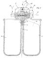
- Fig. 1 the invention is shown with two cups 7, 8, which are attached to a central part 41.
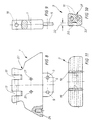
- the middle part 41 has a continuous horizontal shaft 35 in a bore in the upper region, slots being provided in the middle of the middle part 41 according to FIGS. 2 and 3, in which the shaft 35 is exposed. 5, which are each arranged in pairs on a jaw 38 according to FIG. 4, are hooked onto the shaft 35 via elongated holes 36 according to FIG. 1.
- the blood bags not shown here, have solidified openings in the upper edge region, into which the bolts 37 according to FIG. 5 are inserted in pairs.
- the bolts 37 consist of a shaft and a bolt head 43 which protects the blood bag against slipping out.
- the blood bag then hangs freely on the bolt 37 of the leg 34 with the jaw 38 according to FIG. 5 and is inserted from this position into a cup 7 according to FIG. 1 or FIG. 2.
- they In a certain pivot position of the jaws 38, they are pushed onto the shaft 35 via the slot-like bore 36 of the leg 34 and pivoted downward. A firm bond of the cup 7 with the blood bags on bolts 37 of the jaws 34 with respect to the central part 41 and its shaft 35 is thus achieved.
- the bent legs 34 are then pushed over the shaft 35 and the weight-loaded jaws 38 are pivoted down into their rest or fastening position, so that there is then a clear fastening.
- the tubes of the blood bag are advantageously very simply attached.
- the hoses are first led out on recesses 44 according to FIGS. 2, 4 and 6 of the clamping jaws 38 and fixed by hand when the legs 34 are suspended in the shaft 35.
- the otherwise necessary threading of the hoses through clamping devices is thus eliminated, since the jaws 38 on the side of the bolts 37 are open.
- the jaws 38 pivot in the direction of the arrow 42, in particular under the action of the forces which occur in the longitudinal direction of the cups 7, 8 during centrifugation.
- the bolts 37 are inserted with their shafts in holes 40 in the jaws 38.
- the central part 41 has a bore 39 in which the bolts 37 face each other with their bolt heads 43 in the manner of a stop.
- Fig. 3 shows the relatively large one-piece design of the jaws 38 and the arrangement of the legs 34 on the shaft 35.
- the central part 41 has lateral troughs, with the aid of which the entire holder can be grasped.
- the entire holder with the cups 7, 8 is suspended in an arm of the centrifuging device via bores of the central part 41, not shown here.
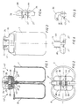
- Fig. 2 shows the oval design of the cups 7, 8, which are attached with their straight sides to the central part 41, preferably by riveting. It can here several smaller cups can also be provided symmetrically or a single cup with one or two jaws on a horizontal shaft 35.
- each blood bag 28 rests in an associated cup 7, 8, both cups 7, 8 being connected to one another by a fastening part 1 in that the fastening part 1 engages with a shoulder 5 in the space 6 between the cups 7, 8 and in the region this approach, a rivet connection 9 is provided, which connects the cups 7, 8 to the approach 5.
- the cups 7, 8 together with the holder according to the invention are inserted into the suspension of a centrifuge in a manner known per se, the centrifuging force acting in the direction of the arrow 25.
- Each blood bag has, in a manner known per se, an edge region 30, which is produced by welding and which passes into a cavity filled with blood or, depending on the intended use, filled with another liquid, which essentially fills the cup 7, 8 in each case.
- Tubes adjoin the edge region 30 of the blood bag 28, only one tube 29 being shown in the exemplary embodiment according to FIG.
- the object of the holder according to the invention is now to generate a clamping force in the edge region 30 of the blood bag, so that the edge region 30 is securely supported during the centrifugation process and at the same time the tubes 29 are led out of the blood bag 28 while avoiding kinks.
- two spaced slots 17 are provided on the upper side of the fastening part, into which one end of each lever 2 pivotably engages, the pivot axis being formed by a dowel pin 18 extending through the entire bore of the fastening part 1.
- the respective lever 2 is supported with its end with play in the slot 17 in order to ensure easy pivoting.
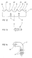
- a mutual spacing - threaded holes 21 are provided, in each of which the threaded shaft of a pin ( Figure 13) is screwed.
- Each pin has a head 10 of an enlarged diameter, which merges into a shaft of smaller diameter.
- the diameter of the head 10 is dimensioned such that it fits tightly through the opening of the blood bag, as a result of which the opening of the blood bag then lies on the shaft of the reduced diameter of the pin 4.
- a bore 24 according to FIG. 8 is arranged on the underside of the fastening part on each side of the fastening part 1, into which a stud bolt, not shown, engages, which in turn engages is firmly connected to the suspension of the centrifuge and looks out of the suspension above.
- each pin 4 engages in an associated recess 2O on the inside of the jaw 3, the depth 32 (see FIG. 10) is chosen so that it is avoided with certainty that the head 10 of the pin 4 to the bottom the recess 2O strikes when the jaw is pressed in the direction of arrow 26 with its inner clamping surface against the fastening part 1.
- the clamping surface of the respective jaw 3 is formed by clamping grooves 23, which receive recesses 12 to 16 between them, through which the tubes 29 of the blood bag 28 are led out without being kinked or pressed.
- a bevel 33 (see FIG. 10) is provided in order to prevent the clamping jaw from contacting the blood bag outside the edge region 30 of the blood bag 28 and possibly including any liquid located there.
- the fastening part 1 is provided on its upper side according to Figure 8 with mutually opposite recessed grips 22, so that the entire fastening part 1 together with the cups attached to it can be easily removed from the hanger of the centrifuge, as a result of which the bores 24 with the stud bolts (not shown) on the hanger disengage.
- the clamping jaw is simply pivoted upwards by hand in the opposite direction to the arrow direction 26, with a holding bevel 31 being provided on the outside of the clamping jaw according to FIG. 10 in order to ensure a favorable gripping with the fingers.
- the pin 4 is exposed and the blood bag 28 is placed with its opening on the pin, as a result of which the head 10 slips through the opening with a slight deformation of the opening and the blood bag then on the shaft reduced diameter of the pin 4 rests.
- the clamping jaw is simply released and swivels automatically under the influence of its weight in the direction of arrow 26 into the position shown in FIG. 7, the hose outlets resting correctly in the recesses 12-16 according to FIG. 12.
- a permanent magnet is arranged in each case, which cooperates with an associated iron strip in the opposite surface of the fastening part, so that this results in a magnetic holding of the clamping jaws in the area shown in FIG. 7 shown location is shown.
Landscapes
- External Artificial Organs (AREA)
- Centrifugal Separators (AREA)
- Medical Preparation Storing Or Oral Administration Devices (AREA)
Claims (10)
- Attache pour sachets de sang disposées dans l'appareil de suspension d'une centrifugeuse, le sachet de sang possédant au moins deux orifices ménages dans la zone du bord et l'attache étant pourvue de goupilles qui traversent les orifices du sachet de sang et qui empêchent celui-ci, ainsi que ses tuyaux disposés dans la zone de raccordement du sachet de sang, de se replier pendant l'opération de centrifugation, caractérisée en ce que les chevilles (37) formant la suspension du sachet de sang sont disposées au niveau de mâchoires (38) qui sont aptes à être suspendues, à l'aide de branches coudées (34) et par l'intermédiaire de perçages (36) en forme de trous longitudinaux, à une broche horizontale (35) au-dessus des godets (8), au niveau d'une partie médiane (41), les mâchoires (38) pivotant au niveau de ladite partie médiane (41) sous l'effet de la force centrifuge (fig. 1).
- Attache pour sachets de sang selon la revendication 1, caractérisée en ce que les chevilles (37) des mâchoires (38) sont disposées symétriquement l'une par rapport à l'autre et sont voisines, au niveau de leur tête, dans une cavité (39) de la partie médiane (41).
- Attache pour sachets de sang selon la revendication 1, caractérisée en ce que les mâchoires (38) sont associées respectivement, en une seule pièce, à deux branches coudées (34).
- Attache pour sachets de sang disposées dans l'appareil de suspension d'une centrifugeuse, le sachet de sang possédant au moins deux orifices ménagés dans la zone du bord et l'attache étant pourvue de goupilles qui traversent les orifices du sachet de sang et qui empêchent celui-ci, ainsi que ses tuyaux disposés dans la zone de raccordement du sachet de sang, de se replier pendant l'opération de centrifugation, caractérisée en ce que les goupilles (4) formant la suspension du sachet de sang (28) sont disposées au niveau d'une pièce de fixation (1) sur laquelle sont montées, pivotantes, des mâchoires de serrage (3) qui entourent les goupilles (4) et appuient contre la zone du bord (39) du sachet de sang (28), sous l'effet de la force de serrage croissante de la force de centrifugation (fig. 7).
- Attache selon la revendication 4, caractérisée en ce que chaque mâchoire de serrage (3) est fixée à l'extrémité pivotante libre d'un levier coudé (2), et en ce que l'axe de pivotement (goupille cylindrique 18) est disposé au niveau de la pièce de fixation (1).
- Attache selon la revendication 4, caractérisée en ce qu'il est associé à chaque sachet de sang (28), en vue de la fixation de deux sachets de sang, un godet (7, 8), en ce que la pièce d'attache (1) pénètre, par une partie saillante (5), dans l'espace intermédiaire (6) séparant les godets (7, 8) et est reliée à cet endroit auxdits godets (7, 8), et en ce qu'il est prévu, sur la pièce de fixation (1), des mâchoires de serrage (3) comportant chacune un sachet de sang (28), qui sont montées pivotantes, par l'intermédiaire de leviers (2) tous situés dans le même axe de pivotement (goupille cylindrique 18).
- Attache selon la revendication 4, caractérisée en ce que chaque mâchoire de serrage (3) possède des nervures de serrage (23) espacées les unes des autres et en ce qu'il est prévu, dans l'espace intermédiaire séparant ces nervures de serrage (23), des cavités (12) pour le passage sans pliage et sans pression des tuyaux (29) du sachet de sang (28).
- Attache selon l'une des revendications 4 à 7, caractérisée en ce que la goupille (4) pénètre dans une cavité (20) de la mâchoire de serrage (3), dont la profondeur (32) est telle que la tête (10) de la goupille (4) ne touche pas le fond de la cavité (20) lorsque la mâchoire de serrage (3) vient buter, au niveau de ses nervures de serrage (23), contre la pièce de fixation (1).
- Attache selon l'une des revendications 4 à 8, caractérisée en ce que chaque goupille (4) se compose d'une tête (10) de diamètre supérieur et d'une tige de diamètre inférieur dans le prolongment de celle-ci.
- Attache selon l'une des revendications 4 à 9, caractérisée en ce qu'il est prévu, dans la zone de la surface de serrage (nervures de serrage (23)) de la mâchoire de serrage (3), une liaison magnétique avec la pièce de fixation (1), facilement détachable.
Priority Applications (1)
| Application Number | Priority Date | Filing Date | Title |
|---|---|---|---|
| AT87109849T ATE67435T1 (de) | 1987-02-10 | 1987-07-08 | Halterung fuer blutbeutel. |
Applications Claiming Priority (2)
| Application Number | Priority Date | Filing Date | Title |
|---|---|---|---|
| DE19873704007 DE3704007C1 (en) | 1986-06-18 | 1987-02-10 | Mounting for blood bag |
| DE3704007 | 1987-02-10 |
Publications (3)
| Publication Number | Publication Date |
|---|---|
| EP0278043A2 EP0278043A2 (fr) | 1988-08-17 |
| EP0278043A3 EP0278043A3 (en) | 1989-06-07 |
| EP0278043B1 true EP0278043B1 (fr) | 1991-09-18 |
Family
ID=6320624
Family Applications (1)
| Application Number | Title | Priority Date | Filing Date |
|---|---|---|---|
| EP87109849A Expired - Lifetime EP0278043B1 (fr) | 1987-02-10 | 1987-07-08 | Dispositif de suspension pour poches sanguines |
Country Status (3)
| Country | Link |
|---|---|
| EP (1) | EP0278043B1 (fr) |
| AT (1) | ATE67435T1 (fr) |
| DE (1) | DE3773178D1 (fr) |
Families Citing this family (5)
| Publication number | Priority date | Publication date | Assignee | Title |
|---|---|---|---|---|
| DE4331138C1 (de) * | 1993-09-14 | 1995-01-05 | Heinz Kruessel | Halter für Blutbeutel |
| DE502004007291D1 (de) * | 2004-09-21 | 2008-07-10 | Hettich Andreas Gmbh & Co Kg | Vorrichtung und Verfahren zum Trennen von in Beuteln befindlichen Blutkomponenten |
| US7744821B2 (en) | 2004-09-21 | 2010-06-29 | Andreas Hettich Gmbh & Co. Kg | Blood bag cup for centrifuges |
| FR2968568B1 (fr) | 2010-12-14 | 2013-01-18 | Maco Pharma Sa | Dispositif destine a rompre au moins un element de fermeture dispose a l'interieur d'un tube souple |
| CN117085862B (zh) * | 2023-09-19 | 2026-02-24 | 郑州中科生物医学工程技术研究院 | 一种离心机用血袋仓 |
Family Cites Families (1)
| Publication number | Priority date | Publication date | Assignee | Title |
|---|---|---|---|---|
| DE7314447U (de) * | 1973-04-16 | 1973-07-26 | Heraeus Christ Gmbh | Vorrichtung zum einsetzen von blutbeuteln in schwenkbecher von zentrifugen |
-
1987
- 1987-07-08 AT AT87109849T patent/ATE67435T1/de not_active IP Right Cessation
- 1987-07-08 EP EP87109849A patent/EP0278043B1/fr not_active Expired - Lifetime
- 1987-07-08 DE DE8787109849T patent/DE3773178D1/de not_active Expired - Lifetime
Also Published As
| Publication number | Publication date |
|---|---|
| EP0278043A2 (fr) | 1988-08-17 |
| ATE67435T1 (de) | 1991-10-15 |
| DE3773178D1 (de) | 1991-10-24 |
| EP0278043A3 (en) | 1989-06-07 |
Similar Documents
| Publication | Publication Date | Title |
|---|---|---|
| CH657551A5 (de) | Bohr-einrichtung. | |
| EP0229973A2 (fr) | Dispositif de fixation pour attacher un porte-bagages de bicyclette | |
| EP0278043A2 (fr) | Dispositif de suspension pour poches sanguines | |
| DE2649349C2 (de) | Lastabwurfvorrichtung für Flugzeuge, bei denen die Last mit Aufhängebeschlägen an Schwenkhaken aufhängbar ist | |
| EP1048544A1 (fr) | Assemblage articulé pour unités - véhicules de véhicules ferroviaires | |
| DE3704007C1 (en) | Mounting for blood bag | |
| DE2846068C2 (de) | Befestigungsvorrichtung für Rohre o.dgl. Gegenstände | |
| DE1965496B2 (de) | Spannhebelverschluß für Schuhwerk, insbesondere Skistiefel | |
| DE69812386T2 (de) | Seilblockiervorrichtung und melkgerätentnahmevorrichtung mit einer solchen seilblockiervorrichtung | |
| DE1481800B1 (de) | Hebeklaue | |
| CH388894A (de) | Vorrichtung zum Festhalten mindestens einer verschiebbar an einer vertikalen Stange gelagerten Hülse bei schirmartig zusammenklappbaren Wäscheaufhängevorrichtungen | |
| DD153142A5 (de) | Verfahren und vorrichtung zur ringlauferentfernung bei ringspinn-oder ringzwirnmaschinen | |
| DE2621719B2 (de) | Einrichtung zur Verlängerung der Haltespreizen bei elektrischen Installationsgeräten | |
| DE3201138C2 (de) | Verriegelungsvorrichtung zur axialen Festlegung von nicht drehbaren Spulen eines Drahtablaufgerätes mit horizontalen feststehenden Achsen | |
| DE3525322A1 (de) | Vorrichtung zum verspannen mindestens eines containers | |
| DE69907670T2 (de) | Vorrichtung zum verbinden eines fahrzeugs mit einer richtbank | |
| EP3246130B2 (fr) | Dispositif de presse | |
| EP1300360A1 (fr) | Crochet de charge avec une griffe de raccourcissement | |
| DE3930766C1 (en) | Erecting device for hospital bed aid - comprises support tube and bearer tube with fitted clamping slide for handle | |
| DE3504920A1 (de) | Vorrichtung zum einhaengen des gabelbaumes am mast eines surfbrettes | |
| DE8902808U1 (de) | Wagenheber | |
| DE2020910A1 (de) | Gussschleuder,insbesondere fuer zahntechnische Zwecke | |
| DE2707397C2 (de) | Gehäuse für elektrische Geräte | |
| DE8111526U1 (de) | Rigg für Surfbretter | |
| DE466644C (de) | Kuenstliche, an einem Armstumpfsockel anschliessbare Arbeitshand |
Legal Events
| Date | Code | Title | Description |
|---|---|---|---|
| PUAI | Public reference made under article 153(3) epc to a published international application that has entered the european phase |
Free format text: ORIGINAL CODE: 0009012 |
|
| AK | Designated contracting states |
Kind code of ref document: A2 Designated state(s): AT BE CH DE FR GB IT LI NL SE |
|
| PUAL | Search report despatched |
Free format text: ORIGINAL CODE: 0009013 |
|
| AK | Designated contracting states |
Kind code of ref document: A3 Designated state(s): AT BE CH DE FR GB IT LI NL SE |
|
| 17P | Request for examination filed |
Effective date: 19891104 |
|
| 17Q | First examination report despatched |
Effective date: 19901130 |
|
| GRAA | (expected) grant |
Free format text: ORIGINAL CODE: 0009210 |
|
| AK | Designated contracting states |
Kind code of ref document: B1 Designated state(s): AT BE CH DE FR GB IT LI NL SE |
|
| PG25 | Lapsed in a contracting state [announced via postgrant information from national office to epo] |
Ref country code: IT Free format text: LAPSE BECAUSE OF FAILURE TO SUBMIT A TRANSLATION OF THE DESCRIPTION OR TO PAY THE FEE WITHIN THE PRE;WARNING: LAPSES OF ITALIAN PATENTS WITH EFFECTIVE DATE BEFORE 2007 MAY HAVE OCCURRED AT ANY TIME BEFORE 2007. THE CORRECT EFFECTIVE DATE MAY BE DIFFERENT FROM THE ONE RECORDED.SCRIBED TIME-LIMIT Effective date: 19910918 Ref country code: BE Effective date: 19910918 Ref country code: FR Effective date: 19910918 Ref country code: SE Effective date: 19910918 Ref country code: GB Effective date: 19910918 Ref country code: NL Effective date: 19910918 |
|
| REF | Corresponds to: |
Ref document number: 67435 Country of ref document: AT Date of ref document: 19911015 Kind code of ref document: T |
|
| REF | Corresponds to: |
Ref document number: 3773178 Country of ref document: DE Date of ref document: 19911024 |
|
| EN | Fr: translation not filed | ||
| NLV1 | Nl: lapsed or annulled due to failure to fulfill the requirements of art. 29p and 29m of the patents act | ||
| GBV | Gb: ep patent (uk) treated as always having been void in accordance with gb section 77(7)/1977 [no translation filed] | ||
| PG25 | Lapsed in a contracting state [announced via postgrant information from national office to epo] |
Ref country code: AT Effective date: 19920708 |
|
| PLBE | No opposition filed within time limit |
Free format text: ORIGINAL CODE: 0009261 |
|
| STAA | Information on the status of an ep patent application or granted ep patent |
Free format text: STATUS: NO OPPOSITION FILED WITHIN TIME LIMIT |
|
| PG25 | Lapsed in a contracting state [announced via postgrant information from national office to epo] |
Ref country code: CH Effective date: 19920731 Ref country code: LI Effective date: 19920731 |
|
| 26N | No opposition filed | ||
| REG | Reference to a national code |
Ref country code: CH Ref legal event code: PL |
|
| PGFP | Annual fee paid to national office [announced via postgrant information from national office to epo] |
Ref country code: DE Payment date: 19940824 Year of fee payment: 8 |
|
| PG25 | Lapsed in a contracting state [announced via postgrant information from national office to epo] |
Ref country code: DE Effective date: 19960402 |