EP0279049A2 - Poutre support de panneaux de coffrage pour coffrages de béton - Google Patents
Poutre support de panneaux de coffrage pour coffrages de béton Download PDFInfo
- Publication number
- EP0279049A2 EP0279049A2 EP87118329A EP87118329A EP0279049A2 EP 0279049 A2 EP0279049 A2 EP 0279049A2 EP 87118329 A EP87118329 A EP 87118329A EP 87118329 A EP87118329 A EP 87118329A EP 0279049 A2 EP0279049 A2 EP 0279049A2
- Authority
- EP
- European Patent Office
- Prior art keywords
- area
- web
- contact area
- carrier according
- perforations
- Prior art date
- Legal status (The legal status is an assumption and is not a legal conclusion. Google has not performed a legal analysis and makes no representation as to the accuracy of the status listed.)
- Granted
Links
Images

Classifications
-
- E—FIXED CONSTRUCTIONS
- E04—BUILDING
- E04G—SCAFFOLDING; FORMS; SHUTTERING; BUILDING IMPLEMENTS OR AIDS, OR THEIR USE; HANDLING BUILDING MATERIALS ON THE SITE; REPAIRING, BREAKING-UP OR OTHER WORK ON EXISTING BUILDINGS
- E04G17/00—Connecting or other auxiliary members for forms, falsework structures, or shutterings
- E04G17/14—Bracing or strutting arrangements for formwalls; Devices for aligning forms
-
- E—FIXED CONSTRUCTIONS
- E04—BUILDING
- E04C—STRUCTURAL ELEMENTS; BUILDING MATERIALS
- E04C3/00—Structural elongated elements designed for load-supporting
- E04C3/02—Joists; Girders, trusses, or trusslike structures, e.g. prefabricated; Lintels; Transoms; Braces
- E04C3/29—Joists; Girders, trusses, or trusslike structures, e.g. prefabricated; Lintels; Transoms; Braces built-up from parts of different material, i.e. composite structures
- E04C3/292—Joists; Girders, trusses, or trusslike structures, e.g. prefabricated; Lintels; Transoms; Braces built-up from parts of different material, i.e. composite structures the materials being wood and metal
-
- E—FIXED CONSTRUCTIONS
- E04—BUILDING
- E04G—SCAFFOLDING; FORMS; SHUTTERING; BUILDING IMPLEMENTS OR AIDS, OR THEIR USE; HANDLING BUILDING MATERIALS ON THE SITE; REPAIRING, BREAKING-UP OR OTHER WORK ON EXISTING BUILDINGS
- E04G11/00—Forms, shutterings, or falsework for making walls, floors, ceilings, or roofs
- E04G11/36—Forms, shutterings, or falsework for making walls, floors, ceilings, or roofs for floors, ceilings, or roofs of plane or curved surfaces end formpanels for floor shutterings
- E04G11/48—Supporting structures for shutterings or frames for floors or roofs
- E04G11/50—Girders, beams, or the like as supporting members for forms
- E04G2011/505—Girders, beams, or the like as supporting members for forms with nailable or screwable inserts
Definitions
- the invention relates to a formwork panel support for concreting formwork, which is designed as a profiled beam made of bent sheet metal, with a contact area for applying the respective formwork sheet, a web area that supports the contact area and a closing area on the edge of the web area facing away from the contact area.
- formwork panel beams made of bent sheet metal are known with a profile that is essentially C-shaped in cross section, so to speak the middle region of the C the web area, which in the state attached to the formwork sheet is essentially perpendicular to the formwork sheet level, forms the web area, so to speak End area of the C forms the contact area and, so to speak, the other end area of the C forms the end area.
- This known C-profile support made of bent sheet metal can be manufactured particularly easily. However, it is considered structurally unfavorable with regard to its load-bearing capacity, which also contributes to the fact that it is a profile that is wide open on one side. In order to achieve the required static values at all, the known support must be bent from relatively thick sheet metal.
- the invention has for its object to provide a formwork panel support of the type mentioned with better load-bearing capacity or more favorable ratio of price and load-bearing capacity.
- the carrier has a substantially T-shaped profile in cross section, in which the contact area is bent over at least for part of its width, the web area has two spaced web sheet areas and the end area connects the two web sheet areas forms.
- the T-shaped profile could therefore be considered in view of the web area with two spaced web sheet areas and in view of the end area connecting the two web sheet areas -shaped profile.
- the multilayered area of the contact area and the connection of the two web plate areas through the sealing area result in a material accumulation in the outer areas of the beam that is favorable for absorbing the bending stress that comes on the beam. This leads to a higher load-bearing capacity or the possibility of working with a lower plate thickness while maintaining the load-bearing capacity. This results in a more favorable ratio of weight or price to load carrying capacity.
- the contact area is preferably not continuous, but rather has a slot-shaped interruption, so to speak.
- This slot makes the carrier easier to manufacture and is favorable for the insertion of a wooden strip, which is discussed in more detail below. With the exception of this slot, it is preferably a closed profile cross section, which is further conducive to the load carrying capacity.
- the carrier preferably has a wooden strip which is inserted adjacent to the contact area between the two web plate areas. This insertion can be carried out particularly economically by spreading the two web plate regions and then inserting them through the widened slot. It is possible to produce a clamping effect on the wooden strip, in particular if the web plate regions are designed to converge slightly before the wooden strip is inserted and run essentially parallel to one another after the wooden strip is inserted and thereby hold the wooden strip in a clamping manner.
- the two web plate regions preferably have inward-facing projections formed by bending as a (rear) stop for the wooden strip.
- the edges of the slot mentioned can be formed by projections of the contact area, which in turn form a (front) stop for the wooden strip, so that the wooden strip is positively enclosed on all sides.
- the wooden strip used primarily serves to fasten the respective formwork panel to the relevant support, in particular by means of screws inserted from the front of the formwork panel or also by means of nails.
- the end region is partially multi-layered and has the shape of an undercut groove in cross section.
- the undercut groove can be used for the particularly convenient attachment of crossbars or cross belts to the formwork panel supports and / or for attaching auxiliary parts, such as props, concrete consoles, etc.
- the contact area preferably has a row of perforations on one side or on both sides of the web area. These perforations can be used in particular for fastening the formwork panel to the respective support, preferably for screwing on from the rear of the formwork panel.
- the web area has at least one row of perforations, in particular a row of perforations in the area where the wooden strip is inserted.
- This can be a row of perforations which alternately have larger and smaller holes, in particular the smaller holes can be used to additionally fix the wooden strip by means of nails or screws.
- the perforations described in the last two paragraphs can preferably be provided in a grid dimension which is preferably an integral fraction of the standard carrier length. This is a practical relief for the possibility of shortening the carrier, in particular to a shorter standard length, or of placing shorter carriers connected to one another in the longitudinal direction, in order to thereby produce carriers of a larger standard length.
- a series of perforations in the web area in the vicinity of the end area can be used in particular to attach transverse bolts there, in which parts of a connecting and aligning system for connecting beams in the longitudinal direction engage.
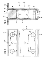
- a bearing area 2 a land area 4 and a termination area 6 of a beam 8 can be seen particularly clearly.
- the beam profile is bent from sheet metal 10.
- the profile shape of the carrier 8 can be considered substantially T-shaped or more precise than -shaped or omega-shaped (if you look at the letter omega with straightening instead of the general rounding).
- the cross section of the beam is completely symmetrical to its central axis 12.
- the web area 4 is formed by two web plate areas 14 running parallel to one another with a mutual spacing of approximately three to fifteen centimeters.
- the sheet 10 is bent outwards by 90 ° and bent back by 180 ° after a distance which is somewhat smaller than the distance between the web sheet area, the bent-back area forming an extension 16 somewhat further in the direction the central axis 12 further goes as corresponds to the web plate area 14 there.
- a slot 18 is thus formed between the two extensions 16, which is slightly narrower than the distance between the two web plate regions 14.
- the sheet metal bends described have created a two-layer contact region 2, the plane of which extends at right angles to the planes of the two web plate regions 14.
- the sheet 10 is first bent inwards by 90 ° on each side, then bent back by a piece by 180 °, then bent again by 90 °, parallel to the edge of the web sheet area 14 in question, and then by 90 ° bent inwards, here, with a continuous sheet 10, so to speak, the connection between the two halves of the carrier 8, which are symmetrical to the central axis 12, is made.
- a bend region 6 is formed by the bends described, which has the shape of an undercut groove and which, with the exception of the actual connecting region 20, has two layers.
- a wooden strip 24 with a square cross section is received in a form-fitting manner.
- the slot 18 has been widened by elastically spreading the web plate regions 14. If the web plate regions 14 run slightly towards one another before the wooden strip 24 is inserted, there is additionally a clamping engagement of the wooden strip 24 between the two web plate regions 14.
- a series of perforations 26 is provided in the contact area 2 on each side of the web area 4. Furthermore, the web plate regions 14 are provided with perforations where the wooden strip 24 is inserted, namely alternately large-diameter perforations 28 and small-diameter perforations 30. Finally, the web plate regions 14 in the vicinity of the end region 6 are each provided with a series of perforations 32. The perforations 28 and the perforations 32 are punched at a mutual pitch a. The perforations 30 are located in the middle between two adjacent perforations 28.
- FIG. 3 shows an example of the construction of a concreting formwork with the aid of beams 8 according to the invention.
- a formwork plate 34 is fastened to a plurality of beams 8 which run parallel to one another, specifically by means of screws which extend from the front of the formwork plate 34 into the wooden strip 24 are screwed, and / or with the aid of screws which are screwed into the back of the formwork plate 34 from the support through the contact area 2.
- the level of the contact area 2 is parallel to the level of the formwork plate 34, and the web area 4 protrudes at right angles from the level of the formwork plate 34.
- a cross bar 36 connects a plurality of beams 8.
- the cross bar 36 is fastened to the beams 8 by inserting a fastening tab, not shown, into the undercut groove 38 of the end region 6 of the respective beam 8 by approximately 90 ° has been rotated to reach behind the groove projections and then tightened by means of a screw bolt 40.
- the nut of the screw bolt is pulled against a further tab 42 which engages behind suitable projections of the cross bar 36.
- FIG. 3 also shows how adjacent beams 8 can be coupled to one another in the longitudinal direction, specifically by means of a connection and alignment system 44.
- This system has a rail 46 which is placed on the end regions 6 of the two beams 8.
- Clamping pieces 48 which cooperate with bolts 50 inserted into the bores 32, clamp the rail 46 between them and the respective carrier 8. This results in a very stable longitudinal connection of two adjacent beams 8 and also an alignment of the two formwork panels 34 which are fastened to the adjacent beams 8.
- the perforations 28 and 32 can in particular also serve as attachment or engagement points for a wide variety of auxiliary parts, for example butt straps, crane hooks, etc.
Landscapes
- Engineering & Computer Science (AREA)
- Architecture (AREA)
- Civil Engineering (AREA)
- Structural Engineering (AREA)
- Mechanical Engineering (AREA)
- Life Sciences & Earth Sciences (AREA)
- Wood Science & Technology (AREA)
- Chemical & Material Sciences (AREA)
- Composite Materials (AREA)
- Forms Removed On Construction Sites Or Auxiliary Members Thereof (AREA)
- Moulds, Cores, Or Mandrels (AREA)
Priority Applications (1)
| Application Number | Priority Date | Filing Date | Title |
|---|---|---|---|
| AT87118329T ATE68843T1 (de) | 1987-02-19 | 1987-12-10 | Schalungsplatten-traeger fuer betonierungsschalungen. |
Applications Claiming Priority (2)
| Application Number | Priority Date | Filing Date | Title |
|---|---|---|---|
| DE3705356 | 1987-02-19 | ||
| DE19873705356 DE3705356A1 (de) | 1987-02-19 | 1987-02-19 | Schalungsplatten-traeger fuer betonierungsschalungen |
Publications (3)
| Publication Number | Publication Date |
|---|---|
| EP0279049A2 true EP0279049A2 (fr) | 1988-08-24 |
| EP0279049A3 EP0279049A3 (en) | 1989-02-01 |
| EP0279049B1 EP0279049B1 (fr) | 1991-10-23 |
Family
ID=6321361
Family Applications (1)
| Application Number | Title | Priority Date | Filing Date |
|---|---|---|---|
| EP87118329A Expired - Lifetime EP0279049B1 (fr) | 1987-02-19 | 1987-12-10 | Poutre support de panneaux de coffrage pour coffrages de béton |
Country Status (4)
| Country | Link |
|---|---|
| EP (1) | EP0279049B1 (fr) |
| AT (1) | ATE68843T1 (fr) |
| DE (2) | DE3705356A1 (fr) |
| ES (1) | ES2027684T3 (fr) |
Cited By (6)
| Publication number | Priority date | Publication date | Assignee | Title |
|---|---|---|---|---|
| WO1995008036A1 (fr) * | 1993-09-13 | 1995-03-23 | Channel Form Systems Inc. | Systeme de poutres en u et de boulons a t |
| EP0869233A1 (fr) * | 1997-04-04 | 1998-10-07 | Encofrados J. Alsina, S.A. | Poutre de coffrage |
| EP0959199A1 (fr) * | 1998-05-19 | 1999-11-24 | Pierangelo Giachino | Elément pour former des coffrages |
| FR2840001A1 (fr) * | 2002-05-27 | 2003-11-28 | Jalmat Ind Mediterranee | Poutre de coffrage et son procede de fabrication |
| EP3073029A1 (fr) | 2015-03-24 | 2016-09-28 | Voestalpine Krems GmbH | Support de coffrage |
| EP3075924A1 (fr) * | 2015-03-30 | 2016-10-05 | Voestalpine Krems GmbH | Fer de traverse destiné à la fixation de support de coffrage |
Families Citing this family (2)
| Publication number | Priority date | Publication date | Assignee | Title |
|---|---|---|---|---|
| RU2120005C1 (ru) * | 1998-03-03 | 1998-10-10 | Соболев Валериан Маркович | Металлодеревянная балка |
| DE102016111211B4 (de) | 2016-06-20 | 2024-11-14 | Ewald Kläs | Schalungssystem für die Errichtung niedriger Bauabschnitte aus Ortbeton |
Family Cites Families (10)
| Publication number | Priority date | Publication date | Assignee | Title |
|---|---|---|---|---|
| US2167835A (en) * | 1937-12-29 | 1939-08-01 | Gerald G Greulich | Structural joist or nailer stud |
| GB560461A (en) * | 1942-08-27 | 1944-04-05 | Walter John Worthington | Improvements in beams for use in building construction |
| DE829783C (de) * | 1943-06-23 | 1952-01-28 | Nat Steel Corp | Nagelbares metallisches Bauelement |
| FR993567A (fr) * | 1949-06-10 | 1951-11-02 | Nat Steel Corp | Perfectionnements aux poutres métalliques |
| NL6906946A (fr) * | 1969-05-07 | 1970-11-10 | ||
| BE780922A (fr) * | 1972-03-20 | 1972-07-17 | Tropimex A G | Structure porteuse pour coffrages, cintres de charpente et analogues |
| GB1551031A (en) * | 1975-04-15 | 1979-08-22 | Catnic Components Ltd | Lintels |
| DE3004860A1 (de) * | 1980-02-09 | 1981-08-20 | geb. Layher Ruth 7129 Güglingen Langer | I-foermiges traegerprofil aus leichtmetall |
| DE8110483U1 (de) * | 1981-04-07 | 1981-10-08 | Schwechheimer, Jürgen, 4053 Jüchen | Schalungstraeger |
| FR2538435B1 (fr) * | 1982-12-22 | 1985-08-23 | Latappy Pierre | Poutrelles en alliage leger a moment d'inertie accru et leur procede de fabrication |
-
1987
- 1987-02-19 DE DE19873705356 patent/DE3705356A1/de not_active Withdrawn
- 1987-12-10 EP EP87118329A patent/EP0279049B1/fr not_active Expired - Lifetime
- 1987-12-10 ES ES198787118329T patent/ES2027684T3/es not_active Expired - Lifetime
- 1987-12-10 DE DE8787118329T patent/DE3774116D1/de not_active Expired - Lifetime
- 1987-12-10 AT AT87118329T patent/ATE68843T1/de not_active IP Right Cessation
Cited By (8)
| Publication number | Priority date | Publication date | Assignee | Title |
|---|---|---|---|---|
| WO1995008036A1 (fr) * | 1993-09-13 | 1995-03-23 | Channel Form Systems Inc. | Systeme de poutres en u et de boulons a t |
| EP0869233A1 (fr) * | 1997-04-04 | 1998-10-07 | Encofrados J. Alsina, S.A. | Poutre de coffrage |
| EP0959199A1 (fr) * | 1998-05-19 | 1999-11-24 | Pierangelo Giachino | Elément pour former des coffrages |
| FR2840001A1 (fr) * | 2002-05-27 | 2003-11-28 | Jalmat Ind Mediterranee | Poutre de coffrage et son procede de fabrication |
| EP3073029A1 (fr) | 2015-03-24 | 2016-09-28 | Voestalpine Krems GmbH | Support de coffrage |
| WO2016151128A1 (fr) | 2015-03-24 | 2016-09-29 | Voestalpine Krems Gmbh | Porte-coffrage et coffrage à béton avec ce porte-coffrage |
| EP3075924A1 (fr) * | 2015-03-30 | 2016-10-05 | Voestalpine Krems GmbH | Fer de traverse destiné à la fixation de support de coffrage |
| WO2016156444A1 (fr) * | 2015-03-30 | 2016-10-06 | Voestalpine Krems Gmbh | Coffrage en béton et traverse associée |
Also Published As
| Publication number | Publication date |
|---|---|
| EP0279049B1 (fr) | 1991-10-23 |
| ES2027684T3 (es) | 1992-06-16 |
| DE3774116D1 (de) | 1991-11-28 |
| EP0279049A3 (en) | 1989-02-01 |
| DE3705356A1 (de) | 1988-09-01 |
| ATE68843T1 (de) | 1991-11-15 |
Similar Documents
| Publication | Publication Date | Title |
|---|---|---|
| DE2546235A1 (de) | Blechriegelschiene zum aufbau von waermeisolierenden bauteilen | |
| EP0293460A1 (fr) | Fenetre de pan de comble a corniere de montage. | |
| DE102020123075A1 (de) | Rahmenschalungselement und Rahmenschalungssystem, Verwendung einer Leiste in einem Rahmenschalungssystem | |
| DE202012104033U1 (de) | Haltevorrichtung für eine Brüstungs- oder Geländerplatte sowie Geländer oder Brüstung mit Scheibe | |
| EP0448120B1 (fr) | Panneau de coffrage pour béton | |
| EP0279049B1 (fr) | Poutre support de panneaux de coffrage pour coffrages de béton | |
| DE2255086C2 (de) | Abstandhaltendes Verbindungsglied zur Herstellung einer mehrschaligen Wand | |
| DE69824076T2 (de) | Befestigungssystem für Platten, insbesondere Platten für belüftete Fassaden | |
| EP4131682A1 (fr) | Pièce tête de liaison permettant de fixer une tige de suspension d'un système de porte-câble à un plafond | |
| DE69326483T2 (de) | Konstruktionsverbindung | |
| EP2862984B1 (fr) | Structure pour le vitrage d'un bâtiment | |
| EP4296453A1 (fr) | Dispositif pour le chargement et le positionnement d'éléments préfabriqués de surfaces de toit | |
| DE29720907U1 (de) | Verbindung von Bauelementen mittels Dreh-/Spannverschlüssen | |
| EP0412445A2 (fr) | Rail pouvant être encastré dans des poutres en béton ou similaires | |
| DE2718135A1 (de) | Schalungstraeger fuer den betonbau | |
| DE29901412U1 (de) | Lochrasterplatte, insbesondere für Textilien-Transportfahrzeuge, Container, Behälter und Aufbauten jeglicher Art | |
| DE2707718A1 (de) | Aus platten zusammengesetzte unterdecke | |
| DE102020126866A1 (de) | Konsole für Fassadenelemente | |
| DE29612053U1 (de) | Bewehrungsvorrichtung | |
| EP1445395B1 (fr) | Système de toiture et procédé de couverture d'une toiture | |
| DE202025104833U1 (de) | Anhebeanordnung zum Anheben eines plattenförmigen Teils | |
| DE2843457A1 (de) | Fassadenverkleidung | |
| DE2710298A1 (de) | Zweiteilige stahlgurtung | |
| EP0274133A2 (fr) | Coffrage pour bétonnage | |
| DE102022202157A1 (de) | Vorrichtung zum Verbinden von Schalelementen mit einem Gurt und einer Kupplung |
Legal Events
| Date | Code | Title | Description |
|---|---|---|---|
| PUAI | Public reference made under article 153(3) epc to a published international application that has entered the european phase |
Free format text: ORIGINAL CODE: 0009012 |
|
| AK | Designated contracting states |
Kind code of ref document: A2 Designated state(s): AT BE CH DE ES FR GB IT LI |
|
| PUAL | Search report despatched |
Free format text: ORIGINAL CODE: 0009013 |
|
| AK | Designated contracting states |
Kind code of ref document: A3 Designated state(s): AT BE CH DE ES FR GB IT LI |
|
| 17P | Request for examination filed |
Effective date: 19890731 |
|
| 17Q | First examination report despatched |
Effective date: 19891005 |
|
| GRAA | (expected) grant |
Free format text: ORIGINAL CODE: 0009210 |
|
| AK | Designated contracting states |
Kind code of ref document: B1 Designated state(s): AT BE CH DE ES FR GB IT LI |
|
| REF | Corresponds to: |
Ref document number: 68843 Country of ref document: AT Date of ref document: 19911115 Kind code of ref document: T |
|
| ITF | It: translation for a ep patent filed | ||
| REF | Corresponds to: |
Ref document number: 3774116 Country of ref document: DE Date of ref document: 19911128 |
|
| GBT | Gb: translation of ep patent filed (gb section 77(6)(a)/1977) | ||
| ET | Fr: translation filed | ||
| REG | Reference to a national code |
Ref country code: ES Ref legal event code: FG2A Ref document number: 2027684 Country of ref document: ES Kind code of ref document: T3 |
|
| PLBE | No opposition filed within time limit |
Free format text: ORIGINAL CODE: 0009261 |
|
| STAA | Information on the status of an ep patent application or granted ep patent |
Free format text: STATUS: NO OPPOSITION FILED WITHIN TIME LIMIT |
|
| 26N | No opposition filed | ||
| REG | Reference to a national code |
Ref country code: GB Ref legal event code: IF02 |
|
| REG | Reference to a national code |
Ref country code: CH Ref legal event code: PUE Owner name: ALPI AG Free format text: DIPL.-ING. NIELS HOLLMANN#NIEDEROLANG 107 B#OLANG (BOLZANO) (IT) -TRANSFER TO- ALPI AG#INDUSTRIEZONE OST#39035 WELSBERG (IT) |
|
| REG | Reference to a national code |
Ref country code: GB Ref legal event code: 732E |
|
| REG | Reference to a national code |
Ref country code: ES Ref legal event code: PC2A |
|
| REG | Reference to a national code |
Ref country code: FR Ref legal event code: TP |
|
| PGFP | Annual fee paid to national office [announced via postgrant information from national office to epo] |
Ref country code: FR Payment date: 20061215 Year of fee payment: 20 |
|
| PGFP | Annual fee paid to national office [announced via postgrant information from national office to epo] |
Ref country code: GB Payment date: 20061218 Year of fee payment: 20 |
|
| PGFP | Annual fee paid to national office [announced via postgrant information from national office to epo] |
Ref country code: ES Payment date: 20061220 Year of fee payment: 20 |
|
| PGFP | Annual fee paid to national office [announced via postgrant information from national office to epo] |
Ref country code: AT Payment date: 20061222 Year of fee payment: 20 |
|
| PGFP | Annual fee paid to national office [announced via postgrant information from national office to epo] |
Ref country code: CH Payment date: 20061227 Year of fee payment: 20 |
|
| PGFP | Annual fee paid to national office [announced via postgrant information from national office to epo] |
Ref country code: IT Payment date: 20061231 Year of fee payment: 20 |
|
| PGFP | Annual fee paid to national office [announced via postgrant information from national office to epo] |
Ref country code: DE Payment date: 20070221 Year of fee payment: 20 |
|
| PGFP | Annual fee paid to national office [announced via postgrant information from national office to epo] |
Ref country code: BE Payment date: 20070627 Year of fee payment: 20 |
|
| BE20 | Be: patent expired |
Owner name: *ALPI A.G. Effective date: 20071210 |
|
| REG | Reference to a national code |
Ref country code: GB Ref legal event code: PE20 |
|
| REG | Reference to a national code |
Ref country code: CH Ref legal event code: PL |
|
| REG | Reference to a national code |
Ref country code: ES Ref legal event code: FD2A Effective date: 20071211 |
|
| PG25 | Lapsed in a contracting state [announced via postgrant information from national office to epo] |
Ref country code: ES Free format text: LAPSE BECAUSE OF EXPIRATION OF PROTECTION Effective date: 20071211 Ref country code: GB Free format text: LAPSE BECAUSE OF EXPIRATION OF PROTECTION Effective date: 20071209 |