EP0279631A2 - Verfahren und Gerät zur Untersuchung von Streifen - Google Patents
Verfahren und Gerät zur Untersuchung von Streifen Download PDFInfo
- Publication number
- EP0279631A2 EP0279631A2 EP88301281A EP88301281A EP0279631A2 EP 0279631 A2 EP0279631 A2 EP 0279631A2 EP 88301281 A EP88301281 A EP 88301281A EP 88301281 A EP88301281 A EP 88301281A EP 0279631 A2 EP0279631 A2 EP 0279631A2
- Authority
- EP
- European Patent Office
- Prior art keywords
- strip
- marking
- properties
- zones
- inspection
- Prior art date
- Legal status (The legal status is an assumption and is not a legal conclusion. Google has not performed a legal analysis and makes no representation as to the accuracy of the status listed.)
- Withdrawn
Links
Images


Classifications
-
- G—PHYSICS
- G01—MEASURING; TESTING
- G01N—INVESTIGATING OR ANALYSING MATERIALS BY DETERMINING THEIR CHEMICAL OR PHYSICAL PROPERTIES
- G01N21/00—Investigating or analysing materials by the use of optical means, i.e. using sub-millimetre waves, infrared, visible or ultraviolet light
-
- G—PHYSICS
- G01—MEASURING; TESTING
- G01N—INVESTIGATING OR ANALYSING MATERIALS BY DETERMINING THEIR CHEMICAL OR PHYSICAL PROPERTIES
- G01N21/00—Investigating or analysing materials by the use of optical means, i.e. using sub-millimetre waves, infrared, visible or ultraviolet light
- G01N21/84—Systems specially adapted for particular applications
- G01N21/88—Investigating the presence of flaws or contamination
- G01N21/89—Investigating the presence of flaws or contamination in moving material, e.g. running paper or textiles
-
- G—PHYSICS
- G01—MEASURING; TESTING
- G01N—INVESTIGATING OR ANALYSING MATERIALS BY DETERMINING THEIR CHEMICAL OR PHYSICAL PROPERTIES
- G01N21/00—Investigating or analysing materials by the use of optical means, i.e. using sub-millimetre waves, infrared, visible or ultraviolet light
- G01N21/84—Systems specially adapted for particular applications
- G01N21/88—Investigating the presence of flaws or contamination
- G01N21/8851—Scan or image signal processing specially adapted therefor, e.g. for scan signal adjustment, for detecting different kinds of defects, for compensating for structures, markings, edges
Definitions
- THE PRESENT INVENTION relates to apparatus and an associated method for providing indicia on a strip identifying specific properties which depart from predetermined ranges.
- organic coatings are generally applied on sheets and the integrity and thickness of such coatings as well as other properties have been monitored.
- U.S. Patent 2,930,228 discloses a system for inspecting a coiled metal strip for various defects and placing markings corresponding to defects within certain zones on an associated tape.
- U.S. Patent 3,455,672 discloses a system for inspecting defects in glass and providing corresponding markings on the glass within the zones where the defects exist.
- U.S. Patent 3,619,578 discloses an inspection device for detecting depressions in softwood veneer by providing a light source, an associated plate member and a sensor monitoring for light passing between the plate member and the veneer.
- apparatus for inspecting strip including inspection means for monitoring a plurality of properties of such strip, transport means for passing said strip past said inspection means, said inspection means having signal generating means for emitting signals related to the properties being monitored when said strip passes thereby, signal processing means for receiving said signals and emitting a responsive error signal when one of said properties in a portion of said strip departs from predetermined property limits, and strip marking means for providing markings in one or more of a plurality of longitudinal zones on said strip responsive to said error signals with each said zone representing a particular type of defect and with said markings being placed within the longitudinal section of said strip wherein said defect exists.
- the system is capable of creating a printout which lists which defects are present in a strip and the longitudinal position at which the defects occur.
- a plurality of marking elements are provided as a unit and are adapted to be positioned in a predetermined position with respect to the longitudinal zones by actuator means which cooperate with strip edge detecting means.
- fabricating equipment for converting into fabricated products a strip marked by the apparatus of the invention, and comprising feed means for feeding said marked strip into said fabricating equipment, and mark decoder means for providing an indication of what defects exist in portions of the strip passing adjacent thereto.
- metal fabricating equipment which receives the marked coil and to have mark decoders monitoring the strip so that as the strip progresses through the metal fabricating equipment, an operator can determine what defects exist within what regions and, if desired, allow those regions to be eliminated or passed through the metal fabricating equipment without fabricating products, thereby enhancing the efficiency of the operation.
- a method of inspecting metal may provide the inspection means for monitoring a plurality of strip properties and emitting signals responsive thereto, marking the strip in a plurality of longitudinal zones each related to a particular strip property when a defect in said property exists and effecting the marking within the section of the strip where said defect exists.
- a method of fabricating products comprising feeding to fabricating equipment strip marked by the inspection apparatus or method of the invention and monitoring the markings on said strip prior to introduction of said strip into said equipment to determine what defects exist and in what portions of said strip.
- the present invention is usable with a wide variety of strip products which may advantageously be presented in coil form.
- a plurality of properties of the strip will be monitored simultaneously and automatically and the sheet marked so as to give a tangible indication as to where a defect exists and as to the nature of the defect.
- properties which might be monitored for example, on a steel strip having a tin or galvanised coating and an organic coating on one surface, would be variations in thickness of the sheet, variations in thickness of the coatings, the presence of undesired pin holes in the sheets, defects in the welds which are frequently used to secure together adjacent longitudinal sections of the coil, and surface defects such as scale, laminations and mill marks, for example.
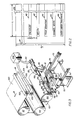
- a coil of metal strip 2 is positioned on a suitable uncoiler and is paid out and advances through an accumulator 4 which may be of a conventional type and have a predetermined number of rolls so as to provide for accumulation of the desired length of strip.
- the strip 3 passes through a weld detection unit 5 which is employed to track coil sequencing through the process.
- the strip 3 then passes through a metal preparation unit 6 within which the strip may be subjected to conventional cleaning and metal treatment operations.
- the strip 3 continues to advance in the direction indicated by the arrows, it passes through a series of inspection devices, which may be of a conventional variety. Shown for purposes of illustration are a pin hole detector 7, a bottom coating weight gauge 8, a top coating weight gauge 9 and a total strip thickness gauge 10. It will be appreciated that other sorts of property monitoring devices may be provided at this point such as a weld integrity gauge or surface inspection gauges, for example.
- a tachometer 11 In the upper left-hand portion of the apparatus there is shown a tachometer 11. This unit provides to a computer (not shown in Figure 1) reference data for use in tracking coil to coil identity as well as reference data significant of the locations, on the strip, of defects as determined by the inspection devices upstream and downstream of the tachometer 11.
- the organic coating applicator unit 12 Downstream of the tachometer 11 is the organic coating applicator unit 12 which provides the organic coating on one or both surfaces of the strip.
- the strip After passing through the organic coater 12, the strip passes through an inspection device 14 which provides an indication of the wet film gauge of the organic coating applied by unit 12. By means of a servo system (not shown) feedback to the coater is provided from the inspection system 14 as well as other feedback.
- the strip 3 then passes through an oven which cures the organic coating applied at station 12. After emerging from the oven 16, the strip passes through a water quench 18 in order to reduce the temperature of the coated strip.
- a dry coating weight gauge to monitor the dry gauge or the organic coating applied in section 12. A servomechanism providing feedback to unit 12 regarding this inspection is also provided.
- an inspector 30 or automated surface inspection system may monitor the strip and visually inspect the same with the ability to take desired action should he, she or it perceive that the organic coating is defective.
- the marking unit of the present invention is preferably introduced to the system at this location with or without the presence of the observer 30. After emerging from the marking station, the coal passes through an additional accumulator 22 and then is wound on to takeup reel 24.
- zone 40 may represent pin holes. Should a pin hole defect occur with zone L anywhere across the width T of the strip, a mark will be placed within zone 40. As a result, a person or automatic facility examining the strip will be informed that a pin hole is present in zone L somewhere within width T of the strip.
- zone 42 may be employed for weld defects
- zone 44 may be used for variations in organic film thickness
- zone 46 may be employed for pin holes in the organic coating
- zone 48 may be used for metal strip being over or under the desired gauge thickness.
- the strip may have a width T of about 30 to 36 inches with the width W of each of the longitudinal zones D being about 0.1 to 5 inches.
- each of the longitudinal zones may be subdivided into smaller units such that position of a marking within the width W of the marking in any of zones 40 to 48, would indicate which quadrant of the full transverse width T of the strip contains the particular defect.
- This may readily be accomplished by means known to those skilled in the art for example by providing inspection devices adapted to provide the computer with data as to which quadrant of the strip width detected defects occur in, by providing additional responsive marking means to provide markings within desired transverse portions of the respective longitudinal zones and by arranging for the computer to control these additional marking means in accordance with the respective more specific signals received from the inspection devices.
- a strip 60 having trailing portion 61 passes through the marking section of the equipment in a direction indicated by arrow B, passes over guide rolls 62, 64, and then around guide roll 66 with the leading edge 63 emerging therefrom.
- the marking station has a foundation 70 with the marking unit 72 providing a plurality of marker dispensing outlets.
- Marker dispenser 76 has an outlet 78 and a hose 82 connecting it with a source 84 of the marking material to be deposited, such as paint, for example.
- the additional marking elements 88, 90, 92, 94, 96, 98 are positioned in relative transverse spaced relationship preferably with substantially equal spacing between adjacent discharge nozzles which spacing corresponds to the centre-to-centre spacing of the longitudinal zones 40-48 on the metal strip.
- a pair of rails 74, 75 support the wheeled carriages 77, 79 on which the marking unit is mounted to permit relative movement between the marked unit and roll 66.
- Marking unit 72 has adjacent plate portion 81 which is fixedly secured to the base of support 90.
- Actuator 192 which may preferably be a linear actuator has a projecting piston rod 89 which is secured to plate 81. It will be appreciated that as the rod 94 reciprocates, the plate 81 and the marking unit 72 will be subjected to relative transverse movement with respect to the longitudinal direction of the strip. In this manner, the marking unit may be moved with respect to the strip edge.
- the actuator 192 is secured to base 95 which in turn is supported on element 91.
- the actuator 192 is surmounted by a casing 93 accommodating ancillary control means.
- the sensor In order to effect a precise determination regarding the position of the edge of strip 60 an edge sensor is provided.
- the sensor consists of a light source 100 and an array of sensors 102.
- a suitable edge detector is that sold by North American Manufacturing Co. of Cleveland, Ohio). By determining what portions of the sensors are receiving light it is possible to determine the precise position of the strip edge. Knowing the precise position of the strip edge, and knowing the positions of the marking unit dispensing nozzles such as 78, it is possible precisely to position the marking dispensers within the desired longitudinal zones which are to be marked.
- a source of electrical power 108 energises light source 100 through lead 104 and receives feedback from the sensor arrays 102 through lead 106.
- the linear actuator 192 is operated through leads 110, 112 to precisely position the marking unit.
- a suitable linear actuator is that sold by Rayco International, Inc. of Methel Park, PA. It will be appreciated that in this manner when the width of the strip being processed is changed, or the position of the same on the rolls is changed, proper indexing of the marking units with respect to the desired longitudinal zones may readily be effected. It will be understood that the zones are preferably not physically defined on the strip. However, the markings which are applied will appear within the respective zones. It will be appreciated that hydraulic cylinders or other means for positioning the marking unit 72 may be employed in lieu of linear actuator 192. It will further be appreciated that positioning of the marking unit with respect to the strip edge is preferably effected automatically, for example by means of the computer referred to.
- Figure 5 shows schematically the interrelationship between the marking unit 72, the paint reservoir 84 and one of the discharge nozzles 78.
- the computer will receive signals from a plurality of inspection units 124, 126, 128 which may be inspection devices such as those described hereinbefore in connection with Figure 1, and indicated at 7 to 10, 14 and 20 in Figure 1, or may be other devices depending upon the number and identity of properties which are being measured.
- the inspection devices 124, 126, 128 will send signals, preferably on a very frequent basis, to the computer which in turn will compare the signals with the predetermined allowable values for the property being monitored.
- the computer will emit an error signal to the marking unit 90 at the appropriate time, taking into account the distance, along the strip run, between the relevant inspection device and the marking facility, and the strip advancement as determined by the tachometer, such that the relevant particular nozzle of the marking unit 90 will deposit marking material in the longitudinal zone W related to that property, within the particular sector L where the defect exists.
- the length of the line within sector L will correspond to the length of the particular section wherein the defect occurs. For example, if a coating defect of one-eighth of an inch exists, a mark of one length would be applied to the zone at that location and if the defect were of an inch, the marking applied would be substantially longer.
- the computer 120 may also advantageously provide a printout 130 which contains a matrix identifying which property defects exist and at what longitudinal positions within the coil they exist. This printout may advantageously be employed when the coil is subjected to fabrication of products therefrom.
- a piece of strip fabricating equipment which may be any suitable equipment for converting the strip into fabricated (or semi-fabricated) products.
- the strip 142 passes over support roll 144 and support rolls 150, 152, 154 and 156.
- a mark decoder 160 Positioned upstream of the fabricating equipment 140 is a mark decoder 160 which is adapted to "read" markings on the strip indicating particular defects.
- a series of transversely spaced sensors such as 162, 164, 166 are positioned at transverse positions corresponding to the location of the longitudinal zones on the strip.
- the space between the centre of the first sensor 162 and the adjacent edge of the strip is E which will correspond with the spacing between the edge of the strip and the centre of the first longitudinal zone such as 48.
- the strip is supported by side guide 68.
- a suitable mark decoder may be of the type sold under the trade designation Dolan-Jenner Led-Pak Infrared decoder by Dolan-Jenner of Woburn, MA.
- An operator station 172 is connected to the mark decoder 160 by lead 170 and is adapted to provide the operator of the equipment 140 with an indication of the property profile of the strip portion about to enter the equipment.
- a portion of the strip which is defective may either be severed from the strip prior to introduction of the strip into the equipment 140 as by shearing means (not shown) or the equipment may be turned off to permit the marked strip section to pass therethrough without the product being made therefrom.
- the present invention has provided an efficient automatic means for effectively marking a strip so as to provide a visual indication of where in the strip property defects exist and the specific nature of the defects. All of this is accomplished in an efficient, automated manner and facilitates subsequent use of the coil in the production of products therefrom.
Landscapes
- Analytical Chemistry (AREA)
- Immunology (AREA)
- Physics & Mathematics (AREA)
- Health & Medical Sciences (AREA)
- Life Sciences & Earth Sciences (AREA)
- Chemical & Material Sciences (AREA)
- General Health & Medical Sciences (AREA)
- Biochemistry (AREA)
- Pathology (AREA)
- General Physics & Mathematics (AREA)
- Engineering & Computer Science (AREA)
- Textile Engineering (AREA)
- Investigating Materials By The Use Of Optical Means Adapted For Particular Applications (AREA)
- Length Measuring Devices By Optical Means (AREA)
Applications Claiming Priority (2)
| Application Number | Priority Date | Filing Date | Title |
|---|---|---|---|
| US07/015,695 US4865872A (en) | 1987-02-17 | 1987-02-17 | Strip inspecting apparatus and associated method |
| US15695 | 1987-02-17 |
Publications (2)
| Publication Number | Publication Date |
|---|---|
| EP0279631A2 true EP0279631A2 (de) | 1988-08-24 |
| EP0279631A3 EP0279631A3 (de) | 1990-05-16 |
Family
ID=21773001
Family Applications (1)
| Application Number | Title | Priority Date | Filing Date |
|---|---|---|---|
| EP88301281A Withdrawn EP0279631A3 (de) | 1987-02-17 | 1988-02-16 | Verfahren und Gerät zur Untersuchung von Streifen |
Country Status (8)
| Country | Link |
|---|---|
| US (1) | US4865872A (de) |
| EP (1) | EP0279631A3 (de) |
| JP (1) | JPS63206639A (de) |
| KR (1) | KR910004157B1 (de) |
| AU (1) | AU601813B2 (de) |
| BR (1) | BR8800615A (de) |
| CA (1) | CA1295394C (de) |
| NZ (1) | NZ223538A (de) |
Cited By (3)
| Publication number | Priority date | Publication date | Assignee | Title |
|---|---|---|---|---|
| EP0335155A3 (de) * | 1988-03-26 | 1991-01-02 | BASF Magnetics GmbH | Verfahren sowie Anordnung zur Darstellung von Oberflächenfehlern an Aufzeichnungsträgern |
| WO1998021568A1 (en) * | 1996-11-13 | 1998-05-22 | Svante Björk AB | Arrangement and method for marking defects |
| CN103586166A (zh) * | 2013-09-26 | 2014-02-19 | 中航锂电(洛阳)有限公司 | 一种涂布生产线及其在线自动标识装置 |
Families Citing this family (18)
| Publication number | Priority date | Publication date | Assignee | Title |
|---|---|---|---|---|
| DE4105364C1 (de) * | 1991-02-21 | 1992-05-27 | Zibulla & Sohn Gmbh Raziol Schmierungstechnik, 5860 Iserlohn, De | |
| DE4130677C2 (de) * | 1991-09-14 | 1995-11-23 | Roland Man Druckmasch | Vorrichtung zur lichtelektrischen Überwachung des Laufes von Bahnen in Rotationsdruckmaschinen |
| JP2911685B2 (ja) * | 1992-09-09 | 1999-06-23 | 本州製紙株式会社 | 塗工機における紙切れ防止方法および紙切れ防止装置 |
| EP0685761A1 (de) * | 1994-05-31 | 1995-12-06 | Eastman Kodak Company | Präzisionszentrierung eines mit einem photographischen lichtempfindlichen Material-beschichteten Bandes |
| US5628227A (en) * | 1994-10-06 | 1997-05-13 | Htrc Automation Inc. | Method and apparatus for determining at least one sheet stretch value of a roll of material |
| US5508622A (en) * | 1994-12-14 | 1996-04-16 | Gatzlaff; Harold | Coating defect detector system |
| JPH0924317A (ja) * | 1995-07-12 | 1997-01-28 | Ngk Insulators Ltd | 被覆剤の塗布装置及び塗布方法 |
| US5766352A (en) * | 1996-01-11 | 1998-06-16 | Kuntz Mfg. Co., Inc. | Stripe applicator device |
| US5628574A (en) * | 1996-03-19 | 1997-05-13 | Roll Systems, Inc. | Web error recovery divert system |
| GB9712709D0 (en) * | 1997-06-18 | 1997-08-20 | Crabtree Gateshead Ltd | Sheet coating machine |
| US6231917B1 (en) * | 1998-06-19 | 2001-05-15 | Kabushiki Kaisha Toshiba | Method of forming liquid film |
| DE19906701C1 (de) * | 1999-02-18 | 2000-12-14 | Parsytec Comp Gmbh | Verfahren und Vorrichtung zum Detektieren, Kennzeichnen und Wiederauffinden von Fehlern eines Materialbandes |
| US7564020B2 (en) * | 2005-11-09 | 2009-07-21 | Black & Decker Inc. | System and method for laser detector with marker |
| SE531120C2 (sv) * | 2007-09-25 | 2008-12-23 | Abb Research Ltd | En anordning och ett förfarande för stabilisering och visuell övervakning av ett långsträckt metalliskt band |
| JP5199932B2 (ja) * | 2009-03-25 | 2013-05-15 | 富士フイルム株式会社 | ガスバリア膜の製造方法 |
| KR101378346B1 (ko) * | 2014-01-22 | 2014-04-04 | 하노스 주식회사 | 바이오 마커 코팅 스트립 제조장치 |
| US9589246B2 (en) * | 2014-06-26 | 2017-03-07 | Ford Global Technologies, Llc | Marking the surface of metal coils with material property data |
| CN113030114B (zh) * | 2021-02-25 | 2023-03-17 | 首钢京唐钢铁联合有限责任公司 | 一种带钢检测系统及立式质检台制造方法 |
Family Cites Families (30)
| Publication number | Priority date | Publication date | Assignee | Title |
|---|---|---|---|---|
| US2246906A (en) * | 1939-05-16 | 1941-06-24 | Westinghouse Electric & Mfg Co | Marking device for hole detectors |
| US2576043A (en) * | 1950-05-19 | 1951-11-20 | United States Steel Corp | Apparatus for detecting and marking pin holes |
| US2930228A (en) * | 1956-11-30 | 1960-03-29 | United States Steel Corp | Apparatus for detecting and recording defects in a strip |
| US3188478A (en) * | 1962-01-11 | 1965-06-08 | Melvin J Binks | Pinhole detector optical system |
| US3269178A (en) * | 1963-08-02 | 1966-08-30 | Kohler Coating Machinery Corp | Paper machine flaw detecting and marking apparatus |
| GB1077561A (en) * | 1964-02-18 | 1967-08-02 | Omron Tateisi Electronics Co | System of detecting and marking defects in a moving web |
| US3445672A (en) * | 1966-08-15 | 1969-05-20 | Philco Ford Corp | Flaw detection and marking system |
| US3448279A (en) * | 1966-10-17 | 1969-06-03 | Lindly & Co Inc | Photoelectric defect detector having reflection test transmission test and edgewise test |
| US3500437A (en) * | 1968-04-09 | 1970-03-10 | Scott Paper Co | Marker device |
| US3619578A (en) * | 1969-09-22 | 1971-11-09 | Canadian Patents Dev | Indicating surface depressions in a material |
| US3633211A (en) * | 1969-10-17 | 1972-01-04 | American Electronic Lab | Inspection recorder means |
| US3700909A (en) * | 1972-03-09 | 1972-10-24 | Columbia Research Corp | Method for detecting pinhole defects in foil material |
| DE2433683C3 (de) * | 1974-07-12 | 1979-02-22 | Erwin Sick Gmbh Optik-Elektronik, 7808 Waldkirch | Vorrichtung zur Überwachung einer Materialbahn auf Fehlstellen |
| JPS5296084A (en) * | 1976-02-06 | 1977-08-12 | Konan Camera Res Inst | System for processing surface flaw |
| JPS5340037A (en) * | 1976-09-27 | 1978-04-12 | Daikin Ind Ltd | Electrically controlled marking apparatuses |
| US4099482A (en) * | 1977-05-11 | 1978-07-11 | Smrt Thomas John | Marking apparatus with measuring device |
| IT1077171B (it) * | 1977-05-20 | 1985-05-04 | Anic Spa | Detettore e registratore di fori e strappi per fogli e nastri in materia plastica |
| DE2726454B2 (de) * | 1977-06-11 | 1979-08-23 | Hoesch Werke Ag, 4600 Dortmund | Verfahren zum Kennzeichnen von bewegten Tafeln und Bändern |
| CH623281A5 (de) * | 1977-10-27 | 1981-05-29 | Sig Schweiz Industrieges | |
| JPS554781A (en) * | 1978-08-17 | 1980-01-14 | Pioneer Video Corp | Movable mirror unit |
| US4204012A (en) * | 1978-11-01 | 1980-05-20 | Opelika Manufacturing Corp. | Sheet inspection and marking system |
| DE2930870C2 (de) * | 1979-07-30 | 1981-04-02 | Felten & Guilleaume Carlswerk AG, 5000 Köln | Verfahren und Vorrichtung zum Herstellen von lackisolierten Wickeldrähten, insbesondere Starkdrähten |
| US4306808A (en) * | 1979-12-14 | 1981-12-22 | Ford Aerospace & Communications Corp. | Glass flaw inspection system |
| JPS5761483A (en) * | 1980-09-29 | 1982-04-13 | Kobe Steel Ltd | Measuring device for steel plate |
| DD201435A1 (de) * | 1981-11-27 | 1983-07-20 | Andreas Engel | Verfahren und einrichtung zur bestimmung von falzabweichungen |
| JPS59180316A (ja) * | 1983-03-31 | 1984-10-13 | Toshiba Corp | 放射線厚さ計 |
| DE3325125C1 (de) * | 1983-07-12 | 1985-02-14 | Erwin Sick Gmbh Optik-Elektronik, 7808 Waldkirch | Anordnung zur Markierung von Fehlstellen an schnell laufenden Materialbahnen |
| US4514436A (en) * | 1983-07-28 | 1985-04-30 | At&T Technologies, Inc. | Methods of highlighting pinholes in a surface layer of an article |
| DE3439313C2 (de) * | 1984-10-26 | 1994-07-07 | Focke & Co | Vorrichtung zum Verbinden von Bahnen aus Verpackungsmaterial |
| US4817424A (en) * | 1987-02-17 | 1989-04-04 | Enamel Products & Planting Company | Strip inspecting apparatus and associated method |
-
1987
- 1987-02-17 US US07/015,695 patent/US4865872A/en not_active Expired - Fee Related
-
1988
- 1988-02-12 BR BR8800615A patent/BR8800615A/pt unknown
- 1988-02-12 AU AU11681/88A patent/AU601813B2/en not_active Ceased
- 1988-02-15 KR KR8801537A patent/KR910004157B1/ko not_active Expired
- 1988-02-16 EP EP88301281A patent/EP0279631A3/de not_active Withdrawn
- 1988-02-16 CA CA000558984A patent/CA1295394C/en not_active Expired - Fee Related
- 1988-02-16 JP JP63033842A patent/JPS63206639A/ja active Pending
- 1988-02-16 NZ NZ223538A patent/NZ223538A/xx unknown
Cited By (4)
| Publication number | Priority date | Publication date | Assignee | Title |
|---|---|---|---|---|
| EP0335155A3 (de) * | 1988-03-26 | 1991-01-02 | BASF Magnetics GmbH | Verfahren sowie Anordnung zur Darstellung von Oberflächenfehlern an Aufzeichnungsträgern |
| WO1998021568A1 (en) * | 1996-11-13 | 1998-05-22 | Svante Björk AB | Arrangement and method for marking defects |
| US6295129B1 (en) | 1996-11-13 | 2001-09-25 | Svante Bjork Ab | Arrangement and method for marking defects |
| CN103586166A (zh) * | 2013-09-26 | 2014-02-19 | 中航锂电(洛阳)有限公司 | 一种涂布生产线及其在线自动标识装置 |
Also Published As
| Publication number | Publication date |
|---|---|
| US4865872A (en) | 1989-09-12 |
| CA1295394C (en) | 1992-02-04 |
| KR880010325A (ko) | 1988-10-08 |
| KR910004157B1 (en) | 1991-06-22 |
| EP0279631A3 (de) | 1990-05-16 |
| AU601813B2 (en) | 1990-09-20 |
| BR8800615A (pt) | 1988-09-27 |
| JPS63206639A (ja) | 1988-08-25 |
| AU1168188A (en) | 1988-08-18 |
| NZ223538A (en) | 1990-05-28 |
Similar Documents
| Publication | Publication Date | Title |
|---|---|---|
| US4865872A (en) | Strip inspecting apparatus and associated method | |
| EP1953616B1 (de) | Verfahren zur Erstellung eines optimierten Schnittplans für ein streifenförmiges Material | |
| EP1030172B1 (de) | Verfahren und Vorrichtung zum Detektieren, Kennzeichnen und Wiederauffinden von Fehlern eines Materialbandes | |
| US11738495B2 (en) | Apparatus and method for automatically analyzing extruded films | |
| US2930228A (en) | Apparatus for detecting and recording defects in a strip | |
| CN101024314B (zh) | 波纹纸板内嵌入rfid标签的方法 | |
| US4817424A (en) | Strip inspecting apparatus and associated method | |
| JP7684998B2 (ja) | 基準マーカを有するバッテリ電極の改善されたトレーサビリティ | |
| US20060090319A1 (en) | Defect locating system for moving web | |
| US5975745A (en) | Method of and apparatus for measuring curl of web, method of and apparatus for correcting curl of web, and apparatus for cutting web | |
| JP2021502623A (ja) | 薄製品のログを製造する方法及びプラント | |
| CN118434658A (zh) | 参考点标记设备及卷图生成设备 | |
| FI111413B (fi) | Laite kaavinterän kuluman mittaamiseksi sekä menetelmä kaavinterän kulumisen mittauksessa | |
| CN114813741A (zh) | 一种管棒材缺陷在线标识装置及方法 | |
| US6264793B1 (en) | Method and apparatus for measuring caliper of paper | |
| US20120247643A1 (en) | Tape flaw and splice avoidance | |
| US5872715A (en) | Automatic inspection and certification system | |
| US4330941A (en) | Measuring linear displacement of an object | |
| CN113074645A (zh) | 检查线开卷带头形状不规则区域和跑偏的检测装置及方法 | |
| AT408580B (de) | Messvorrichtung zumindest zur ermittlung der dicke einer bahn sowie verfahren hierfür | |
| JP2001347315A (ja) | 欠陥マーキングしたコイルの製造方法、欠陥マーキング方法及び欠陥マーキングしたコイルの作業方法 | |
| CN224168051U (zh) | 一种用于圆管状产品的质量检测系统 | |
| JP2004351711A (ja) | ホース連続生産ラインにおける異常検出方法及びその異常検出部の識別検出装置 | |
| JPS597657A (ja) | ロ−ルペ−パ−製造装置 | |
| CN118354969A (zh) | 参考点标记设备及卷图生成设备 |
Legal Events
| Date | Code | Title | Description |
|---|---|---|---|
| PUAI | Public reference made under article 153(3) epc to a published international application that has entered the european phase |
Free format text: ORIGINAL CODE: 0009012 |
|
| AK | Designated contracting states |
Kind code of ref document: A2 Designated state(s): BE DE FR GB IT LU NL |
|
| PUAL | Search report despatched |
Free format text: ORIGINAL CODE: 0009013 |
|
| AK | Designated contracting states |
Kind code of ref document: A3 Designated state(s): BE DE FR GB IT LU NL |
|
| 17P | Request for examination filed |
Effective date: 19901112 |
|
| STAA | Information on the status of an ep patent application or granted ep patent |
Free format text: STATUS: THE APPLICATION IS DEEMED TO BE WITHDRAWN |
|
| 18D | Application deemed to be withdrawn |
Effective date: 19920903 |