EP0279855B1 - Befestigungsanordnung - Google Patents
Befestigungsanordnung Download PDFInfo
- Publication number
- EP0279855B1 EP0279855B1 EP87906340A EP87906340A EP0279855B1 EP 0279855 B1 EP0279855 B1 EP 0279855B1 EP 87906340 A EP87906340 A EP 87906340A EP 87906340 A EP87906340 A EP 87906340A EP 0279855 B1 EP0279855 B1 EP 0279855B1
- Authority
- EP
- European Patent Office
- Prior art keywords
- sections
- interfitting
- crests
- troughs
- hole
- Prior art date
- Legal status (The legal status is an assumption and is not a legal conclusion. Google has not performed a legal analysis and makes no representation as to the accuracy of the status listed.)
- Expired - Lifetime
Links
- 238000004873 anchoring Methods 0.000 claims abstract description 34
- 239000007787 solid Substances 0.000 claims abstract description 21
- 238000003780 insertion Methods 0.000 claims abstract description 18
- 230000037431 insertion Effects 0.000 claims abstract description 18
- 239000002991 molded plastic Substances 0.000 claims abstract description 4
- 239000000463 material Substances 0.000 claims description 13
- 230000000295 complement effect Effects 0.000 claims description 4
- 230000003014 reinforcing effect Effects 0.000 claims description 4
- 230000014759 maintenance of location Effects 0.000 claims 1
- 230000009471 action Effects 0.000 description 5
- 238000012986 modification Methods 0.000 description 3
- 230000004048 modification Effects 0.000 description 3
- 239000004033 plastic Substances 0.000 description 3
- 229920003023 plastic Polymers 0.000 description 3
- 239000004743 Polypropylene Substances 0.000 description 2
- 230000001419 dependent effect Effects 0.000 description 2
- 239000011796 hollow space material Substances 0.000 description 2
- 239000002184 metal Substances 0.000 description 2
- -1 polypropylene Polymers 0.000 description 2
- 229920001155 polypropylene Polymers 0.000 description 2
- 239000004677 Nylon Substances 0.000 description 1
- 230000001154 acute effect Effects 0.000 description 1
- 230000015572 biosynthetic process Effects 0.000 description 1
- 238000006073 displacement reaction Methods 0.000 description 1
- 238000005553 drilling Methods 0.000 description 1
- 229920002457 flexible plastic Polymers 0.000 description 1
- 238000002347 injection Methods 0.000 description 1
- 239000007924 injection Substances 0.000 description 1
- 238000009434 installation Methods 0.000 description 1
- 230000003993 interaction Effects 0.000 description 1
- 230000007246 mechanism Effects 0.000 description 1
- 238000000034 method Methods 0.000 description 1
- 238000000465 moulding Methods 0.000 description 1
- 229920001778 nylon Polymers 0.000 description 1
- 238000005192 partition Methods 0.000 description 1
- 230000009467 reduction Effects 0.000 description 1
- 238000010079 rubber tapping Methods 0.000 description 1
- 239000011343 solid material Substances 0.000 description 1
- 238000005728 strengthening Methods 0.000 description 1
- 239000012815 thermoplastic material Substances 0.000 description 1
- 230000003313 weakening effect Effects 0.000 description 1
Images

Classifications
-
- F—MECHANICAL ENGINEERING; LIGHTING; HEATING; WEAPONS; BLASTING
- F16—ENGINEERING ELEMENTS AND UNITS; GENERAL MEASURES FOR PRODUCING AND MAINTAINING EFFECTIVE FUNCTIONING OF MACHINES OR INSTALLATIONS; THERMAL INSULATION IN GENERAL
- F16B—DEVICES FOR FASTENING OR SECURING CONSTRUCTIONAL ELEMENTS OR MACHINE PARTS TOGETHER, e.g. NAILS, BOLTS, CIRCLIPS, CLAMPS, CLIPS OR WEDGES; JOINTS OR JOINTING
- F16B13/00—Dowels or other devices fastened in walls or the like by inserting them in holes made therein for that purpose
- F16B13/04—Dowels or other devices fastened in walls or the like by inserting them in holes made therein for that purpose with parts gripping in the hole or behind the reverse side of the wall after inserting from the front
-
- F—MECHANICAL ENGINEERING; LIGHTING; HEATING; WEAPONS; BLASTING
- F16—ENGINEERING ELEMENTS AND UNITS; GENERAL MEASURES FOR PRODUCING AND MAINTAINING EFFECTIVE FUNCTIONING OF MACHINES OR INSTALLATIONS; THERMAL INSULATION IN GENERAL
- F16B—DEVICES FOR FASTENING OR SECURING CONSTRUCTIONAL ELEMENTS OR MACHINE PARTS TOGETHER, e.g. NAILS, BOLTS, CIRCLIPS, CLAMPS, CLIPS OR WEDGES; JOINTS OR JOINTING
- F16B13/00—Dowels or other devices fastened in walls or the like by inserting them in holes made therein for that purpose
- F16B13/04—Dowels or other devices fastened in walls or the like by inserting them in holes made therein for that purpose with parts gripping in the hole or behind the reverse side of the wall after inserting from the front
- F16B13/08—Dowels or other devices fastened in walls or the like by inserting them in holes made therein for that purpose with parts gripping in the hole or behind the reverse side of the wall after inserting from the front with separate or non-separate gripping parts moved into their final position in relation to the body of the device without further manual operation
- F16B13/0808—Dowels or other devices fastened in walls or the like by inserting them in holes made therein for that purpose with parts gripping in the hole or behind the reverse side of the wall after inserting from the front with separate or non-separate gripping parts moved into their final position in relation to the body of the device without further manual operation by a toggle-mechanism
-
- F—MECHANICAL ENGINEERING; LIGHTING; HEATING; WEAPONS; BLASTING
- F16—ENGINEERING ELEMENTS AND UNITS; GENERAL MEASURES FOR PRODUCING AND MAINTAINING EFFECTIVE FUNCTIONING OF MACHINES OR INSTALLATIONS; THERMAL INSULATION IN GENERAL
- F16B—DEVICES FOR FASTENING OR SECURING CONSTRUCTIONAL ELEMENTS OR MACHINE PARTS TOGETHER, e.g. NAILS, BOLTS, CIRCLIPS, CLAMPS, CLIPS OR WEDGES; JOINTS OR JOINTING
- F16B13/00—Dowels or other devices fastened in walls or the like by inserting them in holes made therein for that purpose
- F16B13/12—Separate metal or non-separate or non-metal dowel sleeves fastened by inserting the screw, nail or the like
- F16B13/124—Separate metal or non-separate or non-metal dowel sleeves fastened by inserting the screw, nail or the like fastened by inserting a threaded element, e.g. screw or bolt
-
- F—MECHANICAL ENGINEERING; LIGHTING; HEATING; WEAPONS; BLASTING
- F16—ENGINEERING ELEMENTS AND UNITS; GENERAL MEASURES FOR PRODUCING AND MAINTAINING EFFECTIVE FUNCTIONING OF MACHINES OR INSTALLATIONS; THERMAL INSULATION IN GENERAL
- F16B—DEVICES FOR FASTENING OR SECURING CONSTRUCTIONAL ELEMENTS OR MACHINE PARTS TOGETHER, e.g. NAILS, BOLTS, CIRCLIPS, CLAMPS, CLIPS OR WEDGES; JOINTS OR JOINTING
- F16B21/00—Means for preventing relative axial movement of a pin, spigot, shaft or the like and a member surrounding it; Stud-and-socket releasable fastenings
Definitions
- This invention relates to fastening devices and, more particularly, to multi-function, integrally molded, plastic fasteners which function in hollow, thick or solid support members such as walls or partitions.
- Multi-function plastic expansible fasteners of the type disclosed in U.S. Pat. No. 3,651,734, issued to one of the inventors herein on March 28, 1972, have attained wide-ranging commercial success throughout the world.
- This fastener can act as a wedge in a solid wall and also has the capability of opening, upon insertion through a hollow wall, to provide a positive blind side anchorage so that it can reliably function in this mode as well.
- Modifications of fasteners as disclosed in U.S. Pat. No. 4,181,061, issued to the same inventor on January 1, 1980, have tended to be more limited in their application.
- an integrally molded plastic fastener is disclosed with enhanced load bearing capability but is described as being specifically for use in hollow walls.
- Dowel fasteners for example as described in U.S. Pat. Nos. 4,142,440, and 4,518,291, issued March 6, 1979 and May 21, 1985 respectively, represent other types of fasteners which are exclusively for use in solid wall applications.
- a hole, of sufficient width to permit passage of the anchoring element portion of the fastener is initially formed in a support member such as a wall.
- the anchoring element of the fastener is then inserted therethrough for fixed deployment of the fastener.
- many fastening devices particularly those designed for utilization in hollow wall applications, are specifically designed to permit temporary folding or collapsing of the anchoring elements of the fasteners to reduce the size required for the passage hole. Attempts to actually reduce the dimension of the anchoring elements to concomitantly further reduce hole size have generally only resulted in reduction of the load bearing capability of such fasteners.
- DE-A-2846070 discloses a multi-function anchor, consisting of a tubular body and a pair of pivotable sections, the inner ends of which are moved by an inserted fastener.
- each section is of generally U-shaped cross section, with the limbs interdigitated, leaving a significant hollow space between.
- the fastener is inserted into this hollow space and engages opposite side limbs of the pivotable section.
- This provides only a weak interaction between the fastener and the ends of the sections, U-shaped in cross section, they are also inherently weak. High fixing strength therefore requires the use of a bulky anchor, and a large hole to accommodate it.
- the present invention resides in A multi-function device for fastening items, at will, to any of a hollow, thick or solid support member, wherein at least a portion of the fastening device is inserted within a hole formed in the support member, said fastening device being comprised of an anchoring element connected to a base element having a longitudinal axis, with said anchoring element being capable of movement between a closed minimal dimension position, for insertion within said hole, and a fully opened anchoring position, suitable for use with a hollow support member, wherein said anchoring element passes completely beyond said hole; with said insertion situating said base element within said hole, wherein said longitudinal axis of said base element is in line with the wails of said hole, and said anchoring element is situated into a position, from completely contained within said hole in a solid support member, to a position wherein said anchoring element passes completely beyond said hole in a hollow support member; and said anchoring element passes completely beyond said hole in a hollow support member; and said anchoring element comprising at least two separate sections which are
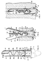
- the fastening device 10 of FIGS. 1 through 7 comprises a base socket element 1 having a bore 2 for receiving an elongated fastening member 16 (shown in FIGS 5-7).
- the bore is preferably dimensioned for threading by a self tapping fastening member such as a screw.
- Base socket element 1 is preferably generally rounded and is integrally joined to pillar-like webs 3. The webs, in turn extend outwardly away from the axis of the base socket element 1 and merge with a pair of outstretched toggle arms 4.
- the base socket element is also preferably fitted at the end thereof opposite the toggle arms 4, with a flange 5 which becomes seated against the exterior wall surface when the fastener is installed in an opening in a solid or hollow wall or the like.
- This flange is preferably dimensioned to have a cross-sectional area approximately 75% greater than the cross-sectional area of the base socket element 1.
- the exterior of the base socket element is also fitted with antirotational fins 6 which engage the wall material and prevent rotation of the fastener in such opening during installation.
- the outer edges of the webs 3 preferably project out away from the exterior surface of the base socket member 1 to act as reinforcing elements and additional antirotation elements, as shown in FIG. 2.
- Inner ends 9 of the toggle arms 4 are separated and spaced from base socket member 1, with the inner ends, together with the pillar like webs 3 and the surface of the base socket element 1, closest to the toggle arms, peripherally defining inner space 8.
- the inner space 8 is suitably dimensioned so that when the toggle arms 4 are folded together for insertion into an opening, the pillar-like webs 3 flex resiliently inwardly toward the axis of the base socket element 1, and the inner ends 9 of the toggle arms 4 pivot down into the inner space, as shown in FIG. 4.
- Groove 7, at the end of the base socket element is oriented to accommodate the material of the hinge-like connection 13 after such material has pivoted down into the inner space 8 upon the folding together of the toggle arms 4 and the collapse of the fastener, as shown in FIG. 4.
- FIGS. 1-3 and 5 show the toggle arms 4 in their molded, outstretched condition.
- the surfaces of the toggle arms 4 facing away from the base socket element 1 are each configured in two sets (a and b) of successive wave crests 10a and 10b and troughs 11a and 11b which extend in direction parallel to the lengths of the toggle arms 4.
- the sets of wave crests and troughs are staggered with respect to each other so that the wave crests 10a are aligned transversely on each toggle arm with the troughs 11b, and the crests 10b being similarly transversely aligned with the troughs 11a, across the width of the toggle arm.
- each toggle arm 4 The wave crests and troughs on each toggle arm 4 are thus positioned in a keyed relationship with the troughs and wave crests on the other toggle arm so that, when the toggle arms are folded together, as shown in FIG. 4, the crests 10a of each toggle arm interfit with the troughs 11a of the other toggle arm, and the crests 10b of each toggle arm interfit with the troughs 11b of the other toggle arm.
- An anchoring element of minimal cross section is formed thereby.
- the outer tip elements of the surfaces having the crests and troughs are configured as flat surfaces 12 which abut each other when the toggle arms are completely folded to facilitate complete and even folding together of the toggle arms.
- the inner ends 9 of the toggle arms 4 are preferably joined together by a hinge-like connection 13 of sufficiently reduced thickness to permit flexing thereof and pivoting of the inner ends 9 of the toggle arms 4 down into the inner space 8 as the toggle arms are folded together.
- the hinge-like connection 13 is provided with a hole 14 coaxially aligned with the bore 2 of the base element 1, to facilitate passage of an elongated fastening member therethrough. The periphery of hole 14 engages the fastening member whereby the toggle arms 4 are locked into a fully extended beam position as shown in Figure 5.
- the fastening device 10 has a central stiffening rib 15 formed, on each of the toggle arms 4, by transversely spacing apart the sets of wave crests and troughs on each toggle arm, as seen in FIGS. 2 and 3.
- This rib provides strengthening of the toggle arms 4 for utilization in hollow or thick walls to compensate for weakening caused by the formation of the troughs.
- the upper peripheries of the sets of crests 10a and 10b which are slightly inwardly inclined toward each other, as seen in FIG. 3, frictionally engage the adjacent wall of the stiffening rib when the toggle arms 4 are juxtaposed, for insertion into a hole into the minimal dimension configuration. This frictional engagement maintains the fastening device 10 in the minimal dimension configuration as shown in FIG.
- fastening device 10 is suitable for automatic insertion with a dispensing mechanism such as a gun.
- the fastening device may be inserted and the toggle arms separated (when used in hollow or thick walls) during a single dispensing procedure.
- the central rib 15 serves the additional purpose of providing a narrow guide for the insertion of the elongated fastening element 16.
- the central rib 15 serves the additional purpose of providing a narrow guide for the insertion of the elongated fastening element 16.
- the surfaces of the toggle arms 4, opposite the surfaces configured with the crests and troughs, are preferably curved so that when the toggle arms 4 are folded together, for insertion into an opening, a partially cylindrical exterior is formed, for a snug fit within the opening of substantially equal diameter. This snug fit increases the wedging action of the fastener when installed in conjunction with an elongated fastening member 16 within an opening in a solid or thick wall or the like.
- This is achieved by molding the inner ends 9 of the toggle area 4 to such a dimension that, upon the pivoting of the toggle arms, a springing action is applied by the resilient webs 3 through the inner ends 9 and to the fulcrum of the pivoting toggle arms at the hinge-like connection 13. With closely juxtaposed but separated ends a key or fastening member serves to move the toggle arms from the collapsed to expanded position.
- the fastener 10 of the present invention may have external holding means integrated with base element 1 as shown in phantom in FIG. 4.
- Such holding means may be in the form of a strap 1' as shown and as more fully described in commonly assigned copending application serial no. 663,613 filed October 22, 1984.
- Other holding means described in said copending application include hooks, rings, cylinders and the like.
- FIGS. 5-7 show the fastener 10 installed in walls 17 a & b, 19 and 20, respectively, of various thicknesses.
- the fastener is locked into position by elongated threaded screw 16 which is at least approximately equal in length to the entire length of the fastener.
- the fastener is initially collapsed for insertion in the holes by the folding together of the toggle arms 4, as shown in FIG. 4. After insertion the antirotation fins 6 become embedded in the material of the walls and screw 16 is inserted into the fastening device until the head 18 thereof becomes flush with the flange 5.
- FIG. 5 shows the fastener installed in a bi-layered wall approximately equal to the length of the base socket element 1 and pillar-like webs 3.
- Screw 16 having passed through the bore 2 engages the inner ends 9 of the toggle arms 4, and pushes them, at the hinge-like connection 13, out of the inner space 8 and through their toggling motion to an unfolded, outstretched locked position.
- the fastener is securely held in the opening by the action of the screw 16 pressing against the inner ends 9 which, in turn, causes the rigid toggle arms 4 to press back against the interior surface of the thin or hollow wall.
- the fastener is thus securely locked in place and the screw 16 is thereby securely held within the opening.
- Any fixture which is desired to be attached to the wall is in turn securely sandwiched between the screw head 18 and the flange 5.
- the two wall layers 17a and 17b are also firmly compressively held together by the fastener.
- FIG.6 shows the fastener installed in a wall 19 of thickness greater than the length of the base socket element 1 and pillar-like webs 3, but not of a thickness as great as the entire length of the fastener.
- the screw 16 passes through the bore 2 and hole 14 into engagement with the interface between adjacent rib portions 15 and wove crests 10a and 10b. This in turn causes the outer curved surfaces of the toggle arms 4 to be securely wedged against the inner surface of the hole in lateral directions away from the axis of the screw, and the portions of the toggle arms extending behind the wall to expand beyond the edges of the opening.
- Angle A between the toggle arms and the screw axis, having a vertex at the juncture of toggle an ends 9, defines the degree to which the toggle arms expand against and behind the wall with a greater angle providing enhanced wedging and shear strength and thus greater load bearing capability.
- the wedging and holding strength is dependent on an angle with a vertex at the point of engagement between the screw and the base element which is more acute relative to the screw axis, with a concomitant lesser degree of wedging and load bearing strength.
- FIG. 7 shows the fastener installed in a solid wall 20 having a drilled opening of a depth slightly greater than the length of the fastening device.
- the load bearing capability of the fastening device is entirely due to the action of the screw 16 upon the wave crests 10a and 10b and the arms 4, which causes the curved outer surfaces of the toggle arms to be firmly wedged against the inner surface of the opening in radial directions away from the axis of the fastener.
- the angle A' between the wedged arms 4 and the screw axis has a vertex at the juncture of toggle arm ends 9 and is thus greater than the wedging angle of prior art fasteners having a vertex at the point of engagement between a screw and the base element.
- a fastener as disclosed herein, comprised of injection molded polypropylene possesses the preferred degree of toughness and resiliency for its usual intended applications.
- Other thermoplastic materials having predetermined strength and flexibility properties sufficient for specific intended applications may also by used.
- the insertion of metal reinforcing elements into portions of the base socket element 1 and/or toggle arms 4 provides greater strength for heavier load applications.
- the molded fastener can also be made to include metal surfaces to be electrically conductive for use in electrical applications.
- the device is preferably formed of a molded flexible plastic material such as polypropylene. Other less flexible but stronger materials such as nylon may be utilized with modifications such as described above.
- the base element may be integrally molded with an external fastening member which holds or supports objects against the support member.
- fastener described above and illustrated in the drawings is illustrative of the present invention and is not to be construed as a limitation on the present invention.
- the fastener is comprised of two toggle arms, additional toggle arms may be utilized with a similar type of nesting for achieving the requisite minimal dimensions for hole insertion.
Landscapes
- General Engineering & Computer Science (AREA)
- Engineering & Computer Science (AREA)
- Mechanical Engineering (AREA)
- Dowels (AREA)
- Seal Device For Vehicle (AREA)
- Paper (AREA)
- Basic Packing Technique (AREA)
- Insertion Pins And Rivets (AREA)
- Injection Moulding Of Plastics Or The Like (AREA)
- Iron Core Of Rotating Electric Machines (AREA)
- Details Of Spanners, Wrenches, And Screw Drivers And Accessories (AREA)
- Slide Fasteners, Snap Fasteners, And Hook Fasteners (AREA)
- Flanged Joints, Insulating Joints, And Other Joints (AREA)
- Finishing Walls (AREA)
- Snaps, Bayonet Connections, Set Pins, And Snap Rings (AREA)
- Window Of Vehicle (AREA)
- Control And Other Processes For Unpacking Of Materials (AREA)
- Gripping Jigs, Holding Jigs, And Positioning Jigs (AREA)
- Orthopedics, Nursing, And Contraception (AREA)
- Materials For Medical Uses (AREA)
- Connection Of Plates (AREA)
- Joining Of Building Structures In Genera (AREA)
- Massaging Devices (AREA)
- Chair Legs, Seat Parts, And Backrests (AREA)
- Sanitary Device For Flush Toilet (AREA)
- Saccharide Compounds (AREA)
Claims (10)
- Vielzweckvorrichtung (10) zur Befestigung von Gegenständen nach Belieben an einem hohlen (17a, 17b), dicken (19) oder massiven Tragbauteil (20), wobei zumindest ein Teil der Befestigungsvorrichtung (10) in eine in dem Tragbauteil (17a & 17b, 19, 20) eingeformte Öffnung eingeführt ist, welche Befestigungsvorrichtung (10) zusammengesetzt ist aus einem Verankerungselement (4), das mit einem Basiselement (1) verbunden ist, welches eine Längsachse aufweist und in der Lage ist, eine Bewegung zwischen einer geschlossenen Stellung mit minimaler Ausdehnung zum Einführen in die besagte Öffnung und einer völlig geöffneten Stellung zur Verankerung auszuführen, geeignet zum Einsatz bei einem Hohlbauteil (17a, 17b), wobei das besagte Verankerungselement (4) vollständig hinter die Öffnung gelangt, mit einer Einbaustellung, in der das Basiselement (1) innerhalb der Öffnung liegt, wobei die betreffende Längsachse des besagten Basiselements (1) mit den Wänden der besagten Öffnung in einer Linie liegt und das besagte Verankerungselement (4) in einer Lage angeordnet ist von gänzlich aufgenommen in der besagten, in einem massiven Tragbauteil (20) befindlichen Öffnung bis zu einer Lage, in welcher das besagte Verankerungselement (4) die besagte Öffnung in einem hohlen Tragbauteil (17a, 17b) vollständig überragt, und wobei besagtes Verankerungselement (4) wenigstens zwei getrennte Abschnitte aufweist, welche in besagter geschlossener Stellung mit minimaler Ausdehnung zueinander parallel sind und ineinandergreifen, wobei die besagten Abschnitte am Basiselement angelenkt und voneinander weg nach außen in eine teilweise oder völlig geöffnete Position schwenkbar sind und die besagten ineinandergreifenden Abschnitte jeweils entsprechende innere Enden (9) haben, welche Mittel zum Eingriff mit einem äußeren Befestigungsteil (16) definieren, das an einem Punkt entfernt und zum Basiselement (1) im Abstand angeordnet ist, und wobei die betreffenden Enden (9) der besagten ineinandergreifenden Abschnitte nebeneinander angeordnet sind, um mit den äußeren Befestigungsteilen (16) dazwischen in Eingriff zu sein,
dadurch gekennzeichnet, daß die besagten Enden entsprechend angrenzende Randbereiche aufweisen, von denen sich jeder stetig in eine Richtung quer zu der Achse des Basiselements (1) und zur Längsrichtung der besagten Abschnitte erstreckt, derart angeordnet, daß sie mit dem Befestigungsteil am Umfang in Bereichen im Eingriff sind, die auf einer Linie zwischen der besagten Achse und den Längsachsen der Abschnitte liegen, daß die Abschnitte in der geschlossenen Stellung direkt aneinander angrenzen und entsprechende komplementäre Oberflächenformen haben, deren Höhe sich über die Länge der Abschnitte in komplementärer Weise derart ändert, daß die Abschnitte in geschlossener Stellung ineinandergreifen und Bereiche mit erhöhter Dicke aufweisen in einer solchen Art, daß in der Stellung mit minimaler Ausdehnung die ineinandergreifenden Abschnitte eine im wesentlichen massive Masse an Material bilden und daß jeder Abschnitt einzelne querlaufende, zueinander im Abstand angeordnete Bereiche aufweist, von denen jeder besagte Oberflächenformen hat, bei denen die Höhe sich über die Länge der Abschnitte ändert, mit einer Unterbrechung in Längsrichtung zwischen diesen Bereichen, um eine enge Führung für das Einführen eines Befestigungselements vorzusehen. - Vorrichtung nach Anspruch 1, wobei besagte Vorrichtung aus Kunststofformmasse besteht und die ineinandergreifenden Abschnitte (4) von einer zur Oberfläche der betreffenden Abschnitte senkrechten Ebene ausgehende Vorsprünge (10a, 10b) und Einformungen (11a, 11b) aufweisen, welche aneinander angrenzen, wenn das Verankerungselement (4) in der geschlossenen Stellung minimaler Ausdehnung, wobei die Vorsprünge 10a, 10b) und die Einformungen (11a, 11b) Wellenberge beziehungsweise Mulden aufweisen, welche aufeinanderfolgend in Form einer Sinuswelle angeordnet sind und deren Abmessung und Lage relativ zueinander so sind, daß sie das nötige Ineinandergreifen ermöglichen, um die geschlossene Stellung mit minimaler Ausdehnung zu erreichen.
- Vorrichtung nach Anspruch 2, wobei besagte ineinandergreifende Abschnitte (4) jeweils von wenigstens zwei Satz von seitlich aneinander angrenzenden aufeinanderfolgenden Wellenbergen (10a, 10b) und Wellentälern (11a, 11b) gebildet sind, welche sich in einer Richtung erstrecken, die mit der Länge der Öffnung fluchtet, wenn das Verankerungselement (4) sich in der Stellung mit minimaler Ausdehnung befindet, und wobei die Wellenberge (10a, 10b) und Wellentäler (11a, 11b) eines jeden der besagten Sätze in bezug auf die Wellenberge und Wellentäler zueinander versetzt angeordnet sind, wobei die Berge (10a, 10b) des einen Satzes mit dem Tal (11a, 11b) des anderen Satzes des betreffenden ineinandergreifenden Abschnittes (4) in Querrichtung fluchten, so daß, wenn die ineinandergreifenden Abschnitte ineinander gesetzt sind, im wesentlichen alle Berge und Täler jeweils ineinander greifen, um die Stellung mit minimaler Ausdehnung zu erreichen und so die besagte weitgehend massive Masse zu bilden.
- Vorrichtung nach Anspruch 3, wobei jeder der ineinandergreifenden Abschnitte ferner Mittel (15) zur Verstärkung aufweist.
- Vorrichtung nach Anspruch 3, wobei besagtes Verankerungselement ferner Mittel umfaßt, welche besagte ineinandergreifende Abschnitte in besagter Stellung mit minimaler Ausdehnung zurückhalten.
- Vorrichtung nach Anspruch 3 mit einem Haltemittel (1') zum Halten von Gegenständen von außen gegen besagtes Tragteil, das in besagtem Basiselement einstückig eingeformt ist.
- Vorrichtung nach Anspruch 4, wobei jeder der besagten ineinandergreifenden Abschnitte (4) zusätzlich Verstärkungsmittel aufweist, die eine versteifende Abstandsrippe (15) enthalten, die längs zwischen den aneinander angrenzenden Sätzen von Wellenbergen (10a, 10b) und Wellentälern (11a, 11b) in jedem der besagten ineinandergreifenden Abschnitte (4) angeordnet ist.
- Vorrichtung nach Anspruch 7, wobei besagte Versteifungsrippe (15) einstückig mit dem Material des ineinandergreifenden Abschnitts (4) ausgebildet ist und sich vertikal wenigstens von dem niedrigsten Punkt des Wellentals (11a, 11b) bis zu einer Höhe erstreckt, die nicht höher liegt als etwa die halbe Dicke des ineinandergreifenden Abschnitts (4).
- Vorrichtung nach Anspruch 7, wobei die besagten Wellenberge (10a, 10b) an ihren oberen Randbereichen leicht nach innen vorgespannt sind, wobei ein reibschlüssiger Eingriff zwischen den Wellenbergen (10a, 10b) und dem angrenzenden Abschnitt der Rippe (15) besteht, wenn die ineinandergreifenden Abschnitte (4) in die ineinandergreifenden Abschnitte eingesetzt sind, die sich hierbei selbsthemmend in der geschlossenen Stellung mit minimaler Ausdehnung befinden, wobei der reibschlüssige Eingriff leicht durch Entfaltung von Mitteln zum Auseinandergehen der ineinandergreifenden Abschnitte beseitigt werden kann.
- Vorrichtung nach Anspruch 1, welche Vorrichtung aus Kunststofformmasse besteht und in der das Verankerungselement (4) wenigstens zwei getrennte ineinandergreifende Längsabschnitte umfaßt, welche miteinander in einer geschlossenen Stellung mit minimaler Ausdehnung im Eingriff sind, welche ineinandergreifenden Abschnitte (4) von einer Ebene senkrecht zur Oberfläche der ineinandergreifenden Abschnitte ausgehende Vorsprünge (10a, 10b) und Einformungen (11a, 11b) aufweisen, welche aneinanderangrenzen, wenn das Verankerungselement (4) sich in der geschlossenen Stellung mit minimaler Ausdehnung befindet, welche Vorsprünge (10a, 10b) und Einformungen (11a, 11b) Berge beziehungsweise Täler aufweisen, welche entlang der Abschnitte aufeinanderfolgend angeordnet sind und Abmessungen sowie eine Lage relativ zueinander haben, die es ihnen gestattet, daß die ineinandergesetzten und die besagten ineinandergreifenden Abschnitte (4) jeweils mit wenigstens zwei seitlich angrenzenden Sätzen von aufeinanderfolgenden Bergen (10a, 10b) und Tälern (11a, 11b) ausgebildet sind, welche sich in einer Richtung erstrecken, die mit der Länge der Öffnung fluchtet, wenn das Verankerungselement (4) seine geschlossene Stellung mit minimaler Ausdehnung einnimmt und in welcher die Berge (10a, 10b) und Täler (11a, 11b) jedes der Sätze in bezug auf die Berge (10a, 10b) und Täler (11a, 11b) des anderen Satzes zueinander versetzt angeordnet sind, so daß, wenn die ineinandergreifenden Abschnitte (4) ineinandergesetzt sind, im wesentlichen alle Berge und Täler jeweils ineinandergreifen, um die Stellung mit minimaler Ausdehnung zu erreichen, dadurch gekennzeichnet, daß jeder der ineinandergreifenden Abschnitte (4) ferner eine versteifende Abstandsrippe (15) enthält, die längs zwischen den aneinander angrenzenden Sätzen von Wellenbergen (10a, 10b) und Wellentälern (11a, 11b) und daß in der geschlossenen Stellung mit minimaler Ausdehnung ineinandergreifenden Abschnitte (4) eine weitgehend feste Masse von Material bilden.
Priority Applications (1)
| Application Number | Priority Date | Filing Date | Title |
|---|---|---|---|
| EP95105082A EP0669471B1 (de) | 1986-09-04 | 1987-09-03 | Befestigungsanordnung |
Applications Claiming Priority (3)
| Application Number | Priority Date | Filing Date | Title |
|---|---|---|---|
| US06/903,636 US4752170A (en) | 1986-09-04 | 1986-09-04 | Fastening device with nesting anchoring elements |
| US903636 | 1986-09-04 | ||
| PCT/US1987/002246 WO1988001700A1 (en) | 1986-09-04 | 1987-09-03 | Fastening device |
Related Child Applications (2)
| Application Number | Title | Priority Date | Filing Date |
|---|---|---|---|
| EP95105082A Division EP0669471B1 (de) | 1986-09-04 | 1987-09-03 | Befestigungsanordnung |
| EP95105082.2 Division-Into | 1995-04-05 |
Publications (3)
| Publication Number | Publication Date |
|---|---|
| EP0279855A1 EP0279855A1 (de) | 1988-08-31 |
| EP0279855A4 EP0279855A4 (en) | 1991-04-24 |
| EP0279855B1 true EP0279855B1 (de) | 1995-11-29 |
Family
ID=25417841
Family Applications (2)
| Application Number | Title | Priority Date | Filing Date |
|---|---|---|---|
| EP87906340A Expired - Lifetime EP0279855B1 (de) | 1986-09-04 | 1987-09-03 | Befestigungsanordnung |
| EP95105082A Expired - Lifetime EP0669471B1 (de) | 1986-09-04 | 1987-09-03 | Befestigungsanordnung |
Family Applications After (1)
| Application Number | Title | Priority Date | Filing Date |
|---|---|---|---|
| EP95105082A Expired - Lifetime EP0669471B1 (de) | 1986-09-04 | 1987-09-03 | Befestigungsanordnung |
Country Status (26)
| Country | Link |
|---|---|
| US (1) | US4752170A (de) |
| EP (2) | EP0279855B1 (de) |
| JP (1) | JPH0733843B2 (de) |
| KR (1) | KR910004258B1 (de) |
| CN (1) | CN1010246B (de) |
| AT (2) | ATE174667T1 (de) |
| AU (1) | AU581387B2 (de) |
| BR (1) | BR8707449A (de) |
| CA (1) | CA1287757C (de) |
| DD (2) | DD271548A5 (de) |
| DE (4) | DE8790057U1 (de) |
| DK (1) | DK163191C (de) |
| ES (1) | ES2008202A6 (de) |
| FI (1) | FI87945C (de) |
| GR (1) | GR871362B (de) |
| HU (1) | HU210384B (de) |
| IE (2) | IE72200B1 (de) |
| IL (1) | IL83581A (de) |
| MX (1) | MX160486A (de) |
| NO (1) | NO174359C (de) |
| NZ (2) | NZ221637A (de) |
| PT (1) | PT85654B (de) |
| RO (1) | RO105278B1 (de) |
| RU (1) | RU1787225C (de) |
| WO (1) | WO1988001700A1 (de) |
| ZA (1) | ZA876559B (de) |
Families Citing this family (28)
| Publication number | Priority date | Publication date | Assignee | Title |
|---|---|---|---|---|
| USD325869S (en) | 1989-07-18 | 1992-05-05 | Admiral Molding Corporation | Toggle anchor |
| US4993901A (en) * | 1990-02-26 | 1991-02-19 | Mechanical Plastics Corp. | Over-center hollow wall anchor with enhanced holding strength |
| US5161296A (en) * | 1991-07-30 | 1992-11-10 | Mechanical Plastics Corp | Method of securing an anchor with extrusion plastic molding in a solid wall substrate |
| FR2745047B1 (fr) * | 1996-02-21 | 1998-04-03 | Spit Soc Prospect Inv Techn | Cheville d'ancrage pour materiaux plein et creux |
| US5938385A (en) * | 1998-05-22 | 1999-08-17 | Garfield; Nathaniel H. | Nested solid, solid wall anchor |
| US6494653B2 (en) | 2001-04-17 | 2002-12-17 | Emerson Electric Company | Wall anchor |
| US20030233095A1 (en) * | 2002-06-12 | 2003-12-18 | Urbanski Mark G. | Device and method for attaching soft tissue to bone |
| FR2849121B1 (fr) * | 2002-12-18 | 2005-08-26 | Prospection & Inventions | Cheville a frapper |
| US20040170559A1 (en) * | 2003-02-28 | 2004-09-02 | Frank Hershkowitz | Hydrogen manufacture using pressure swing reforming |
| US20060165506A1 (en) * | 2004-02-05 | 2006-07-27 | Panasik Cheryl L | Anchor |
| US7762751B2 (en) * | 2004-02-05 | 2010-07-27 | Illinois Tool Works Inc. | Anchor |
| US7001124B2 (en) * | 2004-02-05 | 2006-02-21 | Illinois Tool Works Inc. | Anchor |
| US8764364B2 (en) * | 2004-03-24 | 2014-07-01 | Illinois Tool Works Inc. | System and methods for wall and ceiling fastening |
| US20050278023A1 (en) * | 2004-06-10 | 2005-12-15 | Zwirkoski Paul A | Method and apparatus for filling a cavity |
| US8128670B2 (en) * | 2005-04-15 | 2012-03-06 | Biodynamics Llc | Surgical expansion fasteners |
| USD554488S1 (en) * | 2005-10-14 | 2007-11-06 | International Engineering And Manufacturing, Inc. | Stabilizing stud mount |
| USD577285S1 (en) | 2007-03-28 | 2008-09-23 | Power Fasteners, Inc. | Anchor |
| US8057147B2 (en) | 2008-07-03 | 2011-11-15 | Illinois Tool Works Inc | Self-drilling anchor |
| KR100915189B1 (ko) * | 2008-10-14 | 2009-09-03 | (주)씨스이엔지 | 관 보수용 세그먼트 장치 |
| US7883307B2 (en) | 2009-02-27 | 2011-02-08 | Illinois Tool Works Inc. | Self-drilling fastener |
| US8858143B2 (en) * | 2010-05-03 | 2014-10-14 | Black & Decker Inc. | Wall anchor |
| USD660139S1 (en) * | 2010-09-27 | 2012-05-22 | Powers Products Iii, Llc | Anchor |
| US20120099942A1 (en) * | 2010-10-26 | 2012-04-26 | Powers Products Iii, Llc | Anchor |
| US20140058461A1 (en) * | 2012-08-27 | 2014-02-27 | Michael Black | Fenestrated Bone Screw |
| DE102012018947A1 (de) * | 2012-09-26 | 2014-04-17 | GM Global Technology Operations LLC (n. d. Ges. d. Staates Delaware) | Befestigungselement, insbesondere Käfigmutter |
| GB2562242B (en) | 2017-05-08 | 2020-02-19 | Tavismanor Ltd | Fixing device |
| ES2964328T3 (es) * | 2019-11-04 | 2024-04-05 | Bullfix Ltd | Dispositivo de fijación |
| MX2023000608A (es) | 2022-01-12 | 2023-07-13 | Masonite Corp | Inserto de tornillo y metodo de uso del mismo. |
Family Cites Families (10)
| Publication number | Priority date | Publication date | Assignee | Title |
|---|---|---|---|---|
| FR1289166A (fr) * | 1960-05-14 | 1962-03-30 | Cheville expansible | |
| DE2759958C2 (de) | 1976-07-07 | 1987-10-22 | Arnold Kappel Ch Schefer | |
| AU510498B2 (en) * | 1976-09-15 | 1980-06-26 | Mechanical Plastics Corporation | Expansible fastener |
| JPS5951B2 (ja) * | 1977-12-20 | 1984-01-05 | 東レ株式会社 | ポリエステルフイルムまたはその加工品の密封包装体 |
| DE2819862A1 (de) * | 1978-05-05 | 1979-11-08 | Hilti Ag | Spreizduebel zur hintergreifenden befestigung |
| DE2846070A1 (de) * | 1978-10-23 | 1980-05-08 | Hilti Ag | Spreizduebel mit spreizarmen |
| DE3046290A1 (de) * | 1980-12-09 | 1982-07-08 | Hilti AG, 9494 Schaan | Spreizduebel fuer platten, mauerwerk und dgl. hohlraeume aufweisende bauteile |
| DE3308755A1 (de) * | 1983-03-11 | 1984-09-13 | Hilti Ag, Schaan | Kunststoffspreizduebel |
| GB8401148D0 (en) * | 1984-01-17 | 1984-02-22 | Plas Plugs Ltd | Moulded fixing devices |
| DE3419923A1 (de) * | 1984-05-28 | 1985-11-28 | Hilti Ag, Schaan | Spreizduebel |
-
1986
- 1986-09-04 US US06/903,636 patent/US4752170A/en not_active Expired - Lifetime
-
1987
- 1987-08-18 IL IL83581A patent/IL83581A/xx not_active IP Right Cessation
- 1987-09-01 NZ NZ221637A patent/NZ221637A/en unknown
- 1987-09-01 NZ NZ235381A patent/NZ235381A/en unknown
- 1987-09-02 ZA ZA876559A patent/ZA876559B/xx unknown
- 1987-09-03 IE IE236387A patent/IE72200B1/en not_active IP Right Cessation
- 1987-09-03 JP JP62505788A patent/JPH0733843B2/ja not_active Expired - Lifetime
- 1987-09-03 GR GR871362A patent/GR871362B/el unknown
- 1987-09-03 DD DD87306637A patent/DD271548A5/de not_active IP Right Cessation
- 1987-09-03 CA CA000546098A patent/CA1287757C/en not_active Expired - Lifetime
- 1987-09-03 AU AU80332/87A patent/AU581387B2/en not_active Expired
- 1987-09-03 DE DE8790057U patent/DE8790057U1/de not_active Expired
- 1987-09-03 EP EP87906340A patent/EP0279855B1/de not_active Expired - Lifetime
- 1987-09-03 AT AT95105082T patent/ATE174667T1/de not_active IP Right Cessation
- 1987-09-03 EP EP95105082A patent/EP0669471B1/de not_active Expired - Lifetime
- 1987-09-03 DE DE3751619T patent/DE3751619T2/de not_active Expired - Lifetime
- 1987-09-03 HU HU875190A patent/HU210384B/hu not_active IP Right Cessation
- 1987-09-03 IE IE960741A patent/IE960741L/xx not_active IP Right Cessation
- 1987-09-03 AT AT87906340T patent/ATE130914T1/de not_active IP Right Cessation
- 1987-09-03 DE DE198787906340T patent/DE279855T1/de active Pending
- 1987-09-03 BR BR8707449A patent/BR8707449A/pt not_active IP Right Cessation
- 1987-09-03 DE DE3752243T patent/DE3752243T2/de not_active Expired - Fee Related
- 1987-09-03 WO PCT/US1987/002246 patent/WO1988001700A1/en not_active Ceased
- 1987-09-03 DD DD87332937A patent/DD284952A5/de not_active IP Right Cessation
- 1987-09-04 CN CN87106142A patent/CN1010246B/zh not_active Expired
- 1987-09-04 ES ES8702561A patent/ES2008202A6/es not_active Expired
- 1987-09-04 PT PT85654A patent/PT85654B/pt not_active IP Right Cessation
- 1987-09-04 MX MX8117A patent/MX160486A/es unknown
-
1988
- 1988-04-29 RO RO133315A patent/RO105278B1/ro unknown
- 1988-05-03 DK DK239188A patent/DK163191C/da active
- 1988-05-03 NO NO881935A patent/NO174359C/no unknown
- 1988-05-04 FI FI882093A patent/FI87945C/fi not_active IP Right Cessation
- 1988-05-04 KR KR1019880700503A patent/KR910004258B1/ko not_active Expired
- 1988-05-30 RU SU884355749A patent/RU1787225C/ru active
Also Published As
Similar Documents
| Publication | Publication Date | Title |
|---|---|---|
| EP0279855B1 (de) | Befestigungsanordnung | |
| US4181061A (en) | Fastening element | |
| AU580869B2 (en) | Expansible fastening element | |
| US3651734A (en) | Expansible fastener | |
| US3448651A (en) | Expansion bolts | |
| US4289062A (en) | Expansion dowel | |
| US6254325B1 (en) | Anchor assembly for a wall, floor or like supporting structure | |
| US4089248A (en) | Self-locking unitary molded plastic fastener | |
| US4993901A (en) | Over-center hollow wall anchor with enhanced holding strength | |
| IE960471A1 (en) | Door latch for cooker door | |
| US4712956A (en) | Plastic wall anchor | |
| CZ278958B6 (en) | Fastening detail | |
| CA1248793A (en) | Fastening element | |
| GB2129899A (en) | Expansible anchor | |
| JPH0516403Y2 (de) | ||
| EP0137874B1 (de) | Spreizdübel | |
| JPH0610922A (ja) | 変形可能な締付装置 |
Legal Events
| Date | Code | Title | Description |
|---|---|---|---|
| PUAI | Public reference made under article 153(3) epc to a published international application that has entered the european phase |
Free format text: ORIGINAL CODE: 0009012 |
|
| AK | Designated contracting states |
Kind code of ref document: A1 Designated state(s): AT BE CH DE FR GB IT LI LU NL SE |
|
| ITCL | It: translation for ep claims filed |
Representative=s name: BUGNION S.P.A. |
|
| 17P | Request for examination filed |
Effective date: 19880913 |
|
| TCNL | Nl: translation of patent claims filed | ||
| TCAT | At: translation of patent claims filed | ||
| EL | Fr: translation of claims filed | ||
| DET | De: translation of patent claims | ||
| A4 | Supplementary search report drawn up and despatched |
Effective date: 19910306 |
|
| AK | Designated contracting states |
Kind code of ref document: A4 Designated state(s): AT BE CH DE FR GB IT LI LU NL SE |
|
| 17Q | First examination report despatched |
Effective date: 19920210 |
|
| RAP1 | Party data changed (applicant data changed or rights of an application transferred) |
Owner name: MECHANICAL PLASTICS CORP. |
|
| GRAA | (expected) grant |
Free format text: ORIGINAL CODE: 0009210 |
|
| AK | Designated contracting states |
Kind code of ref document: B1 Designated state(s): AT BE CH DE FR GB IT LI LU NL SE |
|
| REF | Corresponds to: |
Ref document number: 130914 Country of ref document: AT Date of ref document: 19951215 Kind code of ref document: T |
|
| XX | Miscellaneous (additional remarks) |
Free format text: TEILANMELDUNG 95105082.2 EINGEREICHT AM 03/09/87. |
|
| ITF | It: translation for a ep patent filed | ||
| REF | Corresponds to: |
Ref document number: 3751619 Country of ref document: DE Date of ref document: 19960111 |
|
| ET | Fr: translation filed | ||
| REG | Reference to a national code |
Ref country code: CH Ref legal event code: NV Representative=s name: KIRKER & CIE SA |
|
| PLBE | No opposition filed within time limit |
Free format text: ORIGINAL CODE: 0009261 |
|
| STAA | Information on the status of an ep patent application or granted ep patent |
Free format text: STATUS: NO OPPOSITION FILED WITHIN TIME LIMIT |
|
| 26N | No opposition filed | ||
| REG | Reference to a national code |
Ref country code: GB Ref legal event code: IF02 |
|
| PGFP | Annual fee paid to national office [announced via postgrant information from national office to epo] |
Ref country code: AT Payment date: 20050913 Year of fee payment: 19 |
|
| PGFP | Annual fee paid to national office [announced via postgrant information from national office to epo] |
Ref country code: LU Payment date: 20050928 Year of fee payment: 19 |
|
| PGFP | Annual fee paid to national office [announced via postgrant information from national office to epo] |
Ref country code: CH Payment date: 20060830 Year of fee payment: 20 Ref country code: GB Payment date: 20060830 Year of fee payment: 20 |
|
| PGFP | Annual fee paid to national office [announced via postgrant information from national office to epo] |
Ref country code: DE Payment date: 20060831 Year of fee payment: 20 |
|
| PG25 | Lapsed in a contracting state [announced via postgrant information from national office to epo] |
Ref country code: AT Free format text: LAPSE BECAUSE OF NON-PAYMENT OF DUE FEES Effective date: 20060903 |
|
| PGFP | Annual fee paid to national office [announced via postgrant information from national office to epo] |
Ref country code: NL Payment date: 20060903 Year of fee payment: 20 |
|
| PGFP | Annual fee paid to national office [announced via postgrant information from national office to epo] |
Ref country code: FR Payment date: 20060908 Year of fee payment: 20 |
|
| PGFP | Annual fee paid to national office [announced via postgrant information from national office to epo] |
Ref country code: IT Payment date: 20060930 Year of fee payment: 20 |
|
| PGFP | Annual fee paid to national office [announced via postgrant information from national office to epo] |
Ref country code: BE Payment date: 20061110 Year of fee payment: 20 |
|
| REG | Reference to a national code |
Ref country code: GB Ref legal event code: PE20 |
|
| REG | Reference to a national code |
Ref country code: CH Ref legal event code: PL |
|
| NLV7 | Nl: ceased due to reaching the maximum lifetime of a patent |
Effective date: 20070903 |
|
| EUG | Se: european patent has lapsed | ||
| PG25 | Lapsed in a contracting state [announced via postgrant information from national office to epo] |
Ref country code: GB Free format text: LAPSE BECAUSE OF EXPIRATION OF PROTECTION Effective date: 20070902 |
|
| BE20 | Be: patent expired |
Owner name: *MECHANICAL PLASTICS CORP. Effective date: 20070903 |
|
| PG25 | Lapsed in a contracting state [announced via postgrant information from national office to epo] |
Ref country code: NL Free format text: LAPSE BECAUSE OF EXPIRATION OF PROTECTION Effective date: 20070903 |
|
| PGFP | Annual fee paid to national office [announced via postgrant information from national office to epo] |
Ref country code: SE Payment date: 20060906 Year of fee payment: 20 |
|
| PG25 | Lapsed in a contracting state [announced via postgrant information from national office to epo] |
Ref country code: LU Free format text: LAPSE BECAUSE OF NON-PAYMENT OF DUE FEES Effective date: 20060903 |