EP0280080A1 - Dispositif de traitement de la viande de volailles abattues ou similaires - Google Patents
Dispositif de traitement de la viande de volailles abattues ou similaires Download PDFInfo
- Publication number
- EP0280080A1 EP0280080A1 EP88101522A EP88101522A EP0280080A1 EP 0280080 A1 EP0280080 A1 EP 0280080A1 EP 88101522 A EP88101522 A EP 88101522A EP 88101522 A EP88101522 A EP 88101522A EP 0280080 A1 EP0280080 A1 EP 0280080A1
- Authority
- EP
- European Patent Office
- Prior art keywords
- processing machine
- machine according
- workpiece
- cutting
- holding
- Prior art date
- Legal status (The legal status is an assumption and is not a legal conclusion. Google has not performed a legal analysis and makes no representation as to the accuracy of the status listed.)
- Granted
Links
- 235000013372 meat Nutrition 0.000 title claims abstract description 27
- 244000144977 poultry Species 0.000 title claims description 16
- 238000005520 cutting process Methods 0.000 claims abstract description 30
- 238000011144 upstream manufacturing Methods 0.000 claims abstract 3
- 210000000988 bone and bone Anatomy 0.000 claims description 22
- 210000000845 cartilage Anatomy 0.000 claims description 9
- 238000004080 punching Methods 0.000 claims description 9
- 230000036346 tooth eruption Effects 0.000 claims 2
- 238000004026 adhesive bonding Methods 0.000 claims 1
- 241000287828 Gallus gallus Species 0.000 abstract description 4
- 238000006073 displacement reaction Methods 0.000 abstract 4
- 235000013594 poultry meat Nutrition 0.000 description 15
- 210000001519 tissue Anatomy 0.000 description 2
- 235000020990 white meat Nutrition 0.000 description 2
- 241000196324 Embryophyta Species 0.000 description 1
- 240000008415 Lactuca sativa Species 0.000 description 1
- 206010034203 Pectus Carinatum Diseases 0.000 description 1
- 210000001188 articular cartilage Anatomy 0.000 description 1
- 210000000481 breast Anatomy 0.000 description 1
- 239000000969 carrier Substances 0.000 description 1
- 230000007423 decrease Effects 0.000 description 1
- 210000001930 leg bone Anatomy 0.000 description 1
- 238000003754 machining Methods 0.000 description 1
- 238000004519 manufacturing process Methods 0.000 description 1
- 238000000034 method Methods 0.000 description 1
- 235000012045 salad Nutrition 0.000 description 1
- 238000000926 separation method Methods 0.000 description 1
- 230000008719 thickening Effects 0.000 description 1
Images


Classifications
-
- A—HUMAN NECESSITIES
- A22—BUTCHERING; MEAT TREATMENT; PROCESSING POULTRY OR FISH
- A22C—PROCESSING MEAT, POULTRY, OR FISH
- A22C21/00—Processing poultry
- A22C21/0069—Deboning poultry or parts of poultry
- A22C21/0076—Deboning poultry legs and drumsticks
-
- A—HUMAN NECESSITIES
- A22—BUTCHERING; MEAT TREATMENT; PROCESSING POULTRY OR FISH
- A22C—PROCESSING MEAT, POULTRY, OR FISH
- A22C17/00—Other devices for processing meat or bones
- A22C17/02—Apparatus for holding meat or bones while cutting
Definitions
- the invention relates to a processing machine for poultry parts, pieces of meat, or the like. as workpieces with a circulating conveyor, such as a chain, belt, on which, as holding devices, chassis with gripping arms, nail plates or the like. are arranged for holding a workpiece.
- a circulating conveyor such as a chain, belt
- Such a system is to be used, for example, to release the bones of poultry legs. This also enables other pieces of meat to be skeletonized.
- poultry white meat for example chicken breast fillets.
- the white meat located on the poultry legs should also be able to be used, for which purpose rationally working processing systems are required.
- the meat of the chicken drumsticks can be used, for example, to process delicatessen products such as chicken salad with and without skin.
- the invention has for its object to provide a processing machine which makes it possible, particularly in poultry, to remove the meat from bones, cartilage embedded therein, as completely and in large pieces as possible in an automatic run, by cutting or cutting.
- This object is achieved according to the invention in a processing machine of the type mentioned by a cartilage, bone, bone parts or the like. from the meat separating, punch-like, annular cutting device is released, which is mounted on the machine frame automatically displaceable transversely to the direction of movement of the workpiece.
- a processing machine which has a cutting station with a saw band moving parallel to the direction of movement of the transport device and an additional fastening device for the workpiece, such as a piece of meat, poultry part or the like. having. It is thus possible to cut the piece of meat containing the bone, for example a leg of poultry, in the longitudinal direction of the bone in the middle thereof and to remove the two bone halves from the two pieces of meat piece in a simple manner.
- the workpiece on the horizontally movable chassis, projecting from it can be clamped over a smaller part of its length between the gripping arms.
- this part mainly contains tendinous tissue in poultry legs, which is not very much appreciated anyway. With a poultry leg clamped in this way, only the lowest part of the lower leg is clamped, the largest part of the lower leg and the entire upper leg originating from the cartilaginous joint can be used for further processing.
- the piece of meat is preferably clamped in the frozen state at a temperature slightly below 0 ° on the gripping arms of the chassis.
- a processing machine for workpieces has a conveyor drive on a machine frame 10 with a conveyor chain 11 designed as a hinged belt chain, which is guided in horizontal running rails 12.
- Carrying rollers 13 with horizontal axes, on which the chain links 14 are supported, are arranged within the running rails 12, which are designed with a U-profile carrier.
- the conveyor chain 11 has a horizontal upper run and a horizontal lower run located below it.
- Your chain links 14 are connected to one another via hinges 15. At the ends of the runs there are deflection rollers 16, which are mounted on the machine frame 10, for the conveyor chain.
- Connection carriers 17 are fastened to individual chain links 14, on each of which a chassis 18 for receiving a workpiece 19 can be mounted.
- Each chassis has a fixed gripper arm 20 and a pivotable gripper arm 21 which can be pivoted about a pivot axis 22 on the chassis.
- the pivot axis 22 extends in the direction of travel of the chassis 18 moved by the conveyor chain 12.
- the gripping arms 20 and 21 are closed, they form a cavern in which a small length portion of the workpiece 19 can be arranged and clamped.
- the workpieces 19 include, for example, poultry legs such as chicken legs, in which there are still the leg bones connected to one another via a cartilaginous joint 23.
- the workpiece 19 clamped in the chassis 18 protrudes from the top of the chassis 18 with most of its length.
- This cutting station is therefore provided with a band saw, the saw band 24 of which is tensioned on a drive wheel and a deflection wheel 25 located at a distance therefrom.
- the drive wheel and the deflection wheel are arranged at the cutting station with vertical axes of rotation 26 such that the working area of the saw band 24 is above the chassis 18 and the space in which the majority of the workpiece 19 projects from the chassis 18.
- the drive wheel and the deflection wheel 25 can be moved in the vertical direction by a common holding device.
- a horizontal profile carrier 27 which is guided in parallel in the vertical direction along two guide bars 28 at the cutting station.
- a horizontal arm 19 connects the profile carrier 27 to the piston rod 30 of a vertical pressure medium cylinder 31, which is attached to the machine frame 10 and can be designed as a double-acting pneumatic cylinder.
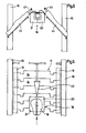
- the cutting station has an additional fastening device, which consists of there are two perpendicular nail plates 32 (FIG. 1) which are mounted with their coaxial shafts 33 and 34 in lifting cylinders 35 which are fastened to the machine frame 10.
- At least one nail plate 32 has a hollow shaft for rotary and transverse movement as a shaft 34, which ends in an annular punching knife 36 which projects at the end of the hollow shaft facing the workpiece 19 and is axially displaceable within the shaft 34 of the nail plate 32.
- the opposite nail plate 31 has a recess 38 in which the punching knife 36 abuts and can thus completely cut through the meat tissue in an annular manner.
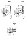
- the hollow shaft 34 is also slidably mounted in the lifting cylinder 35, in which the further slidable hollow shaft 36a is supported with a protruding toothing 50 instead of an annular and uniform cutting edge 36.
- a protruding toothing 50 instead of an annular and uniform cutting edge 36.
- FIG. 8 A further improved version is shown in FIG. 8.
- the hollow shafts 34 and 36a are slidably supported, but between the inner hollow shaft 36a with teeth 50 and the outer hollow shaft 34, a third hollow shaft 51 is mounted, which is also like the inner hollow shaft 36a Can move towards the workpiece 19.
- This middle hollow shaft 51 is formed on the end face as a projecting annular holding surface 52, which lies on the workpiece and additionally holds it in place during the cut.
- only two hollow shafts 53 and 36a are slidably mounted within the lifting cylinder 35, a nail plate 32 being omitted and therefore an end-side widening surface 55 projecting from the outer hollow shaft 53 as a holding device for the workpiece 19.
- a narrowly designed lateral holding surface additionally pushes the near area of the meat around the cartilage joint 23 laterally, so that the cartilage 23 itself is freer to cut.
- 3 and 4 of the drawing show a modified additional fastening device for the workpiece 19.
- This consists of several pairs of conveyor belts assigned to one another. in the first pair of two conveyor belts 39, three rollers 40 with vertical axes are provided on each belt.
- the two conveyor belts 39 are at a horizontal distance from one another. This decreases from a greatest value when the workpiece 19 runs in to a constant smallest value which is so small that the workpiece 19 is held between the conveyor belts 39.
- This pair of conveyor belts 39 can be followed by an upper and a lower pair of conveyor belts 41, which are arranged one above the other keeping a horizontal distance in order to form a passage space for the punching knife 36.
- the conveyor belts 41 are also tensioned on rollers 40 with vertical axes.
- the chassis 18 with the cut workpiece 19 comes into a Cutting station of the processing plant.
- the workpiece 19, which has been cut open for most of its length is still held at its lower end by the gripping arms 20 and 21 of the chassis 18 and moves with its parting line against the tip of an expanding wedge 42.
- the expanding wedge 42 separates the two halves of the workpiece 19, so that these are separated from one another at the clamping point until the bone of the lower leg breaks and can be removed as machined pieces.
- the bone halves 43 can now be removed from the cutting planes of the workpiece parts 44 in a simple manner.
- the processing system has a printing template 45, on the inclined surface 46 of which the pivotable gripper arm 21 slides along while the chassis 18 is traveling and is pressed there on the fixed gripper arms 20 and thus pivoted into the closed position.
- the workpiece 19 fastened in this position moves with the chassis 18 into the cutting station and stops.
- the nail plates 32 move towards the workpiece and hold it in the cutting station, so that the punching out of the cartilaginous joint 23 and the sawing along the bones of the workpiece 19 can then take place.
- the saw band 24 has moved out of the processing area again, the nail plates 32 move back into their starting position, so that the workpiece 19 is released again.
- the chassis 18 can continue to move into the separating station, where the expanding wedge 42 presses the two parts of the workpiece 19 apart until their bone halves 43 break off at the clamping points.
- the workpiece parts 44 thus created can then be removed from the chassis 18 and the bone halves 43 removed are released from the meat.
- the conveyor chain 11 has conveyed the next chassis 18 with a new workpiece 19 into the cutting station for slicing.
- the diameter of the annular cutting device 36, 50 depends on whether only the cartilage 23 alone between an upper lobe and lower lobe (small diameter) or whether the adjacent bone thickenings are also punched out (large diameter).
Landscapes
- Life Sciences & Earth Sciences (AREA)
- Engineering & Computer Science (AREA)
- Wood Science & Technology (AREA)
- Zoology (AREA)
- Food Science & Technology (AREA)
- Processing Of Meat And Fish (AREA)
Priority Applications (1)
| Application Number | Priority Date | Filing Date | Title |
|---|---|---|---|
| AT88101522T ATE70163T1 (de) | 1987-02-07 | 1988-02-03 | Bearbeitungsmaschine fuer gefluegelfleisch o. dgl. |
Applications Claiming Priority (2)
| Application Number | Priority Date | Filing Date | Title |
|---|---|---|---|
| DE3703836A DE3703836C2 (de) | 1987-02-07 | 1987-02-07 | Bearbeitungsanlage für Geflügelfleisch |
| DE3703836 | 1987-02-07 |
Publications (2)
| Publication Number | Publication Date |
|---|---|
| EP0280080A1 true EP0280080A1 (fr) | 1988-08-31 |
| EP0280080B1 EP0280080B1 (fr) | 1991-12-11 |
Family
ID=6320514
Family Applications (1)
| Application Number | Title | Priority Date | Filing Date |
|---|---|---|---|
| EP88101522A Expired - Lifetime EP0280080B1 (fr) | 1987-02-07 | 1988-02-03 | Dispositif de traitement de la viande de volailles abattues ou similaires |
Country Status (6)
| Country | Link |
|---|---|
| US (1) | US4811457A (fr) |
| EP (1) | EP0280080B1 (fr) |
| JP (1) | JP2603678B2 (fr) |
| AT (1) | ATE70163T1 (fr) |
| DE (2) | DE3703836C2 (fr) |
| ES (1) | ES2029855T3 (fr) |
Cited By (5)
| Publication number | Priority date | Publication date | Assignee | Title |
|---|---|---|---|---|
| EP0321718A1 (fr) * | 1987-12-22 | 1989-06-28 | Nordischer Maschinenbau Rud. Baader Gmbh + Co Kg | Dispositif pour enlever la viande des extrémités de volailles |
| EP0544103A1 (fr) * | 1991-10-23 | 1993-06-02 | SCHAAR TEC SPEZIALMASCHINEN GmbH & Co KG | Dispositif pour désosser les ailes de volailles |
| EP0544094A1 (fr) * | 1991-11-27 | 1993-06-02 | Nordischer Maschinenbau Rud. Baader Gmbh + Co Kg | Dispositif pour le traitement des jarrets de volailles |
| FR2696322A1 (fr) * | 1992-10-06 | 1994-04-08 | Arbor Sa | Dispositif de désossage de cuisses de volailles. |
| EP0594934A3 (fr) * | 1992-10-28 | 1994-10-19 | Gordex Corp | Dispositif à désosser des pattes de volailles. |
Families Citing this family (20)
| Publication number | Priority date | Publication date | Assignee | Title |
|---|---|---|---|---|
| DE3838236A1 (de) * | 1987-12-04 | 1990-05-17 | Lohmann Anlagenbau | Vorrichtung zum entbeinen von huehnerkeulen oder dergleichen |
| DE8907406U1 (de) * | 1989-06-16 | 1990-10-18 | Lindert, Heinrich, 4802 Halle | Vorrichtung zum Bearbeiten von Geflügel o.dgl. |
| JPH0732664B2 (ja) * | 1990-01-31 | 1995-04-12 | 有限会社埴生鉄工所 | 動物の肉の切断方法及び切断装置 |
| US5080631A (en) * | 1990-06-04 | 1992-01-14 | James Edwin Mauer | Method and apparatus of cutting the second joint of a poultry wing and product therefrom |
| US5176562A (en) * | 1991-04-26 | 1993-01-05 | Foodcraft Holdings, Inc. | Dark meat deboner with leg scraper |
| US5102369A (en) * | 1991-04-26 | 1992-04-07 | Foodcraft Holdings, Inc. | Dark meat deboner |
| US5494479A (en) * | 1991-10-23 | 1996-02-27 | Schaartec Gmbh & Co.Kg | Device for boning wings of poultry or the like |
| US5277649A (en) * | 1992-12-01 | 1994-01-11 | Systemate Holland B.V. | Method and apparatus for removing meat from poultry legs and thighs |
| NL1012703C2 (nl) * | 1999-04-06 | 2000-10-09 | Stork Pmt | Werkwijze en inrichting voor het bewerken van een gevogeltepoot. |
| SE0500791L (sv) * | 2005-04-07 | 2006-04-25 | Exos Ab | Anordning för att dra ut ben ur fisk |
| US8591298B1 (en) * | 2008-02-21 | 2013-11-26 | Three Dick Farms, Inc. | Poultry wing deboning apparatus and method |
| EP2547212B1 (fr) | 2010-03-16 | 2015-02-25 | FPM INTERNATIONAL, naamloze vennootschap | Procédé pour le traitement d'une partie d'un animal de boucherie et dispositif pour appliquer un tel procédé |
| PL3422714T3 (pl) | 2011-06-30 | 2021-05-31 | JVC Kenwood Corporation | Urządzenie do kodowania obrazu, sposób kodowania obrazu, program do kodowania obrazu, urządzenie do dekodowania obrazu, sposób dekodowania obrazu i program do dekodowania obrazu |
| US8777704B2 (en) * | 2012-06-27 | 2014-07-15 | Foodmate Bv | Method and apparatus for removing the knee cap from a deboned poultry part |
| CN103689053B (zh) * | 2013-12-26 | 2015-04-22 | 安徽华菱西厨装备股份有限公司 | 锯骨机的尾料处理装置 |
| CN107279251B (zh) * | 2017-06-28 | 2019-07-05 | 贺州思通信息技术有限公司 | 一种猪筒骨加工夹具 |
| JP6946169B2 (ja) * | 2017-12-25 | 2021-10-06 | 株式会社前川製作所 | 骨付き肉の軟骨切断装置及び軟骨切断方法 |
| CN111387258A (zh) * | 2018-07-19 | 2020-07-10 | 高宏福 | 一种牛排骨用截断机构及使用方法 |
| CN111958659A (zh) * | 2020-07-21 | 2020-11-20 | 福州聚英智能科技有限公司 | 一种基于多自由度夹持的机器视觉自动锯骨机 |
| AU2021334847A1 (en) * | 2020-08-31 | 2023-03-09 | Marel Meat B.V. | Method and system for deboning of a carcass leg part of a four legged slaughter animal, for removing meat from a bone of the carcass leg part |
Citations (6)
| Publication number | Priority date | Publication date | Assignee | Title |
|---|---|---|---|---|
| US3038197A (en) * | 1959-03-19 | 1962-06-12 | King Mfg Corp | Disjointing machine for carcass limbs |
| US3075236A (en) * | 1960-05-05 | 1963-01-29 | Mann Malden | Apparatus for processing kidney knobs |
| US4041572A (en) * | 1976-09-27 | 1977-08-16 | Victor F. Weaver, Inc. | Anatomical section de-boning machine |
| NL7707771A (en) * | 1977-07-12 | 1979-01-16 | Breins Consulting & Eng | Carcass splitting method using vibratory cutter - which vibrates at a frequency of at least 2000 vibrations per minute, avoiding formation of bone splinters or slime |
| US4385421A (en) * | 1981-05-20 | 1983-05-31 | Victor F. Weaver, Inc. | Poultry leg/back processor |
| NL8302495A (nl) * | 1983-07-13 | 1985-02-01 | Systemate Bv | Snijmachine. |
Family Cites Families (8)
| Publication number | Priority date | Publication date | Assignee | Title |
|---|---|---|---|---|
| US3510908A (en) * | 1967-09-06 | 1970-05-12 | Asa B Segur | Apparatus for stripping meat from skeletal components |
| DE2726918C2 (de) * | 1977-06-15 | 1986-09-04 | K.J. Maskinfabriken A/S, Hjerting | Vorrichtung zum Abtrennen der Speckschicht von Kotelett-Strängen |
| DE2818147C2 (de) * | 1978-04-26 | 1980-02-07 | Maschinenfabrik Dornhan Gmbh & Co, 7242 Dornhan | Bandsägegerät zum Zerteilen von Fleisch und Knochen |
| US4359807A (en) * | 1981-04-28 | 1982-11-23 | Oscar Mayer Foods Corporation | Meat gristle puller |
| US4441411A (en) * | 1983-04-25 | 1984-04-10 | Mullins Jr James N | Slicer for ham or the like |
| NL186429C (nl) * | 1983-11-29 | 1990-12-03 | Maekawa Seisakusho Kk | Inrichting voor het verwijderen van vlees van gewrichten omvattende benen van gevogelte. |
| NL8501363A (nl) * | 1985-05-13 | 1986-12-01 | Systemate Bv | Inrichting voor het ontbenen van dierbotten, zoals dijen van geslachte kippen. |
| US4662029A (en) * | 1985-11-06 | 1987-05-05 | Geo. A. Hormel & Co. | Process and apparatus for cutting hog carcasses |
-
1987
- 1987-02-07 DE DE3703836A patent/DE3703836C2/de not_active Expired - Fee Related
-
1988
- 1988-02-03 EP EP88101522A patent/EP0280080B1/fr not_active Expired - Lifetime
- 1988-02-03 AT AT88101522T patent/ATE70163T1/de not_active IP Right Cessation
- 1988-02-03 DE DE8888101522T patent/DE3866725D1/de not_active Expired - Lifetime
- 1988-02-03 US US07/151,812 patent/US4811457A/en not_active Expired - Fee Related
- 1988-02-03 ES ES198888101522T patent/ES2029855T3/es not_active Expired - Lifetime
- 1988-02-08 JP JP63025871A patent/JP2603678B2/ja not_active Expired - Lifetime
Patent Citations (6)
| Publication number | Priority date | Publication date | Assignee | Title |
|---|---|---|---|---|
| US3038197A (en) * | 1959-03-19 | 1962-06-12 | King Mfg Corp | Disjointing machine for carcass limbs |
| US3075236A (en) * | 1960-05-05 | 1963-01-29 | Mann Malden | Apparatus for processing kidney knobs |
| US4041572A (en) * | 1976-09-27 | 1977-08-16 | Victor F. Weaver, Inc. | Anatomical section de-boning machine |
| NL7707771A (en) * | 1977-07-12 | 1979-01-16 | Breins Consulting & Eng | Carcass splitting method using vibratory cutter - which vibrates at a frequency of at least 2000 vibrations per minute, avoiding formation of bone splinters or slime |
| US4385421A (en) * | 1981-05-20 | 1983-05-31 | Victor F. Weaver, Inc. | Poultry leg/back processor |
| NL8302495A (nl) * | 1983-07-13 | 1985-02-01 | Systemate Bv | Snijmachine. |
Cited By (5)
| Publication number | Priority date | Publication date | Assignee | Title |
|---|---|---|---|---|
| EP0321718A1 (fr) * | 1987-12-22 | 1989-06-28 | Nordischer Maschinenbau Rud. Baader Gmbh + Co Kg | Dispositif pour enlever la viande des extrémités de volailles |
| EP0544103A1 (fr) * | 1991-10-23 | 1993-06-02 | SCHAAR TEC SPEZIALMASCHINEN GmbH & Co KG | Dispositif pour désosser les ailes de volailles |
| EP0544094A1 (fr) * | 1991-11-27 | 1993-06-02 | Nordischer Maschinenbau Rud. Baader Gmbh + Co Kg | Dispositif pour le traitement des jarrets de volailles |
| FR2696322A1 (fr) * | 1992-10-06 | 1994-04-08 | Arbor Sa | Dispositif de désossage de cuisses de volailles. |
| EP0594934A3 (fr) * | 1992-10-28 | 1994-10-19 | Gordex Corp | Dispositif à désosser des pattes de volailles. |
Also Published As
| Publication number | Publication date |
|---|---|
| JPS63276439A (ja) | 1988-11-14 |
| DE3703836C2 (de) | 1995-12-21 |
| DE3703836A1 (de) | 1988-08-18 |
| ATE70163T1 (de) | 1991-12-15 |
| US4811457A (en) | 1989-03-14 |
| ES2029855T3 (es) | 1992-10-01 |
| JP2603678B2 (ja) | 1997-04-23 |
| DE3866725D1 (de) | 1992-01-23 |
| EP0280080B1 (fr) | 1991-12-11 |
Similar Documents
| Publication | Publication Date | Title |
|---|---|---|
| EP0280080B1 (fr) | Dispositif de traitement de la viande de volailles abattues ou similaires | |
| DE69533683T3 (de) | Verfahren und Vorrichtung zum Filetieren des Körpers von Schlachtgeflügel | |
| DE69630178T2 (de) | Verfahren und Vorrichtung zum Bearbeiten von Schlachtgeflügel | |
| DE69302099T2 (de) | Verfahren und Vorrichtung zum Filetieren des Körpers von Schlachtgeflügel | |
| DE3811317C2 (fr) | ||
| EP0402647B1 (fr) | Procédé et dispositif pour le traitement des extrémités de volailles ou similaires | |
| EP0635340B1 (fr) | Dispositif automatique de coupe | |
| DE3020351C2 (fr) | ||
| EP0421991B1 (fr) | Dispositif de traitement de la viande | |
| DE60100042T2 (de) | Vorrichtung zum Spalten mit einem beweglichen Stand | |
| EP0505837A1 (fr) | Procédé et dispositif pour désosser des jarrets de volailles | |
| DE19500014A1 (de) | Einrichtung zum Zerlegen der Flügel von Geflügelkörper | |
| EP2512256B1 (fr) | Dispositif et procédé pour enlever le cartilage costal d'une volaille | |
| DD202496A5 (de) | Verfahren und vorrichtung zum entbeinen von fleisch | |
| DE2254284A1 (de) | Enthaeutemaschine fuer fischfilets | |
| DE3247588C2 (de) | Vorrichtung zum Halbieren von Schlachttierkörpern durch Sägen | |
| DE2850985C2 (de) | Vorrichtung zum Zertrennen von Reifenaufbaumaterial in Stücke | |
| DE69017693T2 (de) | Verfahren und vorrichtung zum ausbeinen von schlachtbauchstücken. | |
| DE19639472A1 (de) | Maschine zum automatischen Entbeinen von Fleischteilen, insbesondere Geflügelschenkel | |
| EP0362457A1 (fr) | Dispositif pour enlever la viande des jarrets de volaille | |
| DE2421339A1 (de) | Verfahren und anordnung zum verarbeiten gehaeuteter rumpfhaelften von rindern oder anderen vierbeinigen schlachttieren | |
| EP1379143B1 (fr) | Procede et dispositif pour lever des filets de poisson (sortie des filets sur bande) | |
| DE1939046C2 (de) | Vorrichtung zum Zweiteilen von Schlachtviehrümpfen | |
| DE3321727C1 (de) | Einrichtung an Fischfiletiermaschinen | |
| DE9113164U1 (de) | Vorrichtung zum Entbeinen von Flügeln von Geflügel o.dgl. |
Legal Events
| Date | Code | Title | Description |
|---|---|---|---|
| PUAI | Public reference made under article 153(3) epc to a published international application that has entered the european phase |
Free format text: ORIGINAL CODE: 0009012 |
|
| AK | Designated contracting states |
Kind code of ref document: A1 Designated state(s): AT BE CH DE ES FR GB IT LI NL SE |
|
| 17P | Request for examination filed |
Effective date: 19890227 |
|
| 17Q | First examination report despatched |
Effective date: 19901001 |
|
| GRAA | (expected) grant |
Free format text: ORIGINAL CODE: 0009210 |
|
| AK | Designated contracting states |
Kind code of ref document: B1 Designated state(s): AT BE CH DE ES FR GB IT LI NL SE |
|
| REF | Corresponds to: |
Ref document number: 70163 Country of ref document: AT Date of ref document: 19911215 Kind code of ref document: T |
|
| BECN | Be: change of holder's name |
Effective date: 19911211 |
|
| REF | Corresponds to: |
Ref document number: 3866725 Country of ref document: DE Date of ref document: 19920123 |
|
| ITF | It: translation for a ep patent filed | ||
| RAP2 | Party data changed (patent owner data changed or rights of a patent transferred) |
Owner name: NORDISCHER MASCHINENBAU RUD. BAADER GMBH + CO KG |
|
| REG | Reference to a national code |
Ref country code: CH Ref legal event code: PUE Owner name: NORDISCHER MASCHINENBAU RUD. BAADER GMBH + CO. KG |
|
| GBT | Gb: translation of ep patent filed (gb section 77(6)(a)/1977) | ||
| EN | Fr: translation not filed | ||
| REG | Reference to a national code |
Ref country code: ES Ref legal event code: FG2A Ref document number: 2029855 Country of ref document: ES Kind code of ref document: T3 |
|
| PLBE | No opposition filed within time limit |
Free format text: ORIGINAL CODE: 0009261 |
|
| STAA | Information on the status of an ep patent application or granted ep patent |
Free format text: STATUS: NO OPPOSITION FILED WITHIN TIME LIMIT |
|
| ITPR | It: changes in ownership of a european patent |
Owner name: CESSIONE;NORDISCHER MASCHINENBAU RUD. BAADER GMBH |
|
| 26N | No opposition filed | ||
| REG | Reference to a national code |
Ref country code: FR Ref legal event code: ST |
|
| REG | Reference to a national code |
Ref country code: FR Ref legal event code: AR |
|
| ET | Fr: translation filed | ||
| REG | Reference to a national code |
Ref country code: FR Ref legal event code: BR |
|
| EAL | Se: european patent in force in sweden |
Ref document number: 88101522.6 |
|
| REG | Reference to a national code |
Ref country code: CH Ref legal event code: PUE Owner name: HEINRICH LINDERT |
|
| NLS | Nl: assignments of ep-patents |
Owner name: HEINRICH LINDERT |
|
| PGFP | Annual fee paid to national office [announced via postgrant information from national office to epo] |
Ref country code: GB Payment date: 19970116 Year of fee payment: 10 |
|
| PGFP | Annual fee paid to national office [announced via postgrant information from national office to epo] |
Ref country code: BE Payment date: 19970121 Year of fee payment: 10 |
|
| PGFP | Annual fee paid to national office [announced via postgrant information from national office to epo] |
Ref country code: AT Payment date: 19970127 Year of fee payment: 10 Ref country code: CH Payment date: 19970127 Year of fee payment: 10 |
|
| PGFP | Annual fee paid to national office [announced via postgrant information from national office to epo] |
Ref country code: FR Payment date: 19970211 Year of fee payment: 10 |
|
| PGFP | Annual fee paid to national office [announced via postgrant information from national office to epo] |
Ref country code: ES Payment date: 19970217 Year of fee payment: 10 |
|
| PGFP | Annual fee paid to national office [announced via postgrant information from national office to epo] |
Ref country code: NL Payment date: 19970227 Year of fee payment: 10 Ref country code: SE Payment date: 19970227 Year of fee payment: 10 Ref country code: DE Payment date: 19970227 Year of fee payment: 10 |
|
| PG25 | Lapsed in a contracting state [announced via postgrant information from national office to epo] |
Ref country code: GB Free format text: LAPSE BECAUSE OF NON-PAYMENT OF DUE FEES Effective date: 19980203 Ref country code: AT Free format text: LAPSE BECAUSE OF NON-PAYMENT OF DUE FEES Effective date: 19980203 |
|
| PG25 | Lapsed in a contracting state [announced via postgrant information from national office to epo] |
Ref country code: SE Free format text: LAPSE BECAUSE OF NON-PAYMENT OF DUE FEES Effective date: 19980204 Ref country code: ES Free format text: LAPSE BECAUSE OF NON-PAYMENT OF DUE FEES Effective date: 19980204 |
|
| PG25 | Lapsed in a contracting state [announced via postgrant information from national office to epo] |
Ref country code: FR Free format text: THE PATENT HAS BEEN ANNULLED BY A DECISION OF A NATIONAL AUTHORITY Effective date: 19980228 Ref country code: CH Free format text: LAPSE BECAUSE OF NON-PAYMENT OF DUE FEES Effective date: 19980228 Ref country code: LI Free format text: LAPSE BECAUSE OF NON-PAYMENT OF DUE FEES Effective date: 19980228 Ref country code: BE Free format text: LAPSE BECAUSE OF NON-PAYMENT OF DUE FEES Effective date: 19980228 |
|
| BERE | Be: lapsed |
Owner name: LINDERT HEINRICH Effective date: 19980228 |
|
| PG25 | Lapsed in a contracting state [announced via postgrant information from national office to epo] |
Ref country code: NL Free format text: LAPSE BECAUSE OF NON-PAYMENT OF DUE FEES Effective date: 19980901 |
|
| GBPC | Gb: european patent ceased through non-payment of renewal fee |
Effective date: 19980203 |
|
| REG | Reference to a national code |
Ref country code: CH Ref legal event code: PL |
|
| EUG | Se: european patent has lapsed |
Ref document number: 88101522.6 |
|
| NLV4 | Nl: lapsed or anulled due to non-payment of the annual fee |
Effective date: 19980901 |
|
| PG25 | Lapsed in a contracting state [announced via postgrant information from national office to epo] |
Ref country code: DE Free format text: LAPSE BECAUSE OF NON-PAYMENT OF DUE FEES Effective date: 19981103 |
|
| REG | Reference to a national code |
Ref country code: FR Ref legal event code: ST |
|
| REG | Reference to a national code |
Ref country code: ES Ref legal event code: FD2A Effective date: 20000403 |
|
| PG25 | Lapsed in a contracting state [announced via postgrant information from national office to epo] |
Ref country code: IT Free format text: LAPSE BECAUSE OF NON-PAYMENT OF DUE FEES Effective date: 20050203 |