EP0280335B1 - Analyse von organischen Substanzen - Google Patents
Analyse von organischen Substanzen Download PDFInfo
- Publication number
- EP0280335B1 EP0280335B1 EP88102940A EP88102940A EP0280335B1 EP 0280335 B1 EP0280335 B1 EP 0280335B1 EP 88102940 A EP88102940 A EP 88102940A EP 88102940 A EP88102940 A EP 88102940A EP 0280335 B1 EP0280335 B1 EP 0280335B1
- Authority
- EP
- European Patent Office
- Prior art keywords
- vessel
- sample
- furnace
- volume
- gases
- Prior art date
- Legal status (The legal status is an assumption and is not a legal conclusion. Google has not performed a legal analysis and makes no representation as to the accuracy of the status listed.)
- Expired - Lifetime
Links
- 238000004458 analytical method Methods 0.000 title description 11
- 239000011368 organic material Substances 0.000 title 1
- 239000007789 gas Substances 0.000 claims description 57
- 239000000203 mixture Substances 0.000 claims description 25
- 238000002485 combustion reaction Methods 0.000 claims description 18
- 238000002156 mixing Methods 0.000 claims description 12
- 239000008246 gaseous mixture Substances 0.000 claims description 11
- 239000000463 material Substances 0.000 claims description 9
- QVGXLLKOCUKJST-UHFFFAOYSA-N atomic oxygen Chemical compound [O] QVGXLLKOCUKJST-UHFFFAOYSA-N 0.000 claims description 8
- 239000001301 oxygen Substances 0.000 claims description 8
- 229910052760 oxygen Inorganic materials 0.000 claims description 8
- 238000007789 sealing Methods 0.000 claims description 8
- 239000012530 fluid Substances 0.000 claims description 6
- RYGMFSIKBFXOCR-UHFFFAOYSA-N Copper Chemical compound [Cu] RYGMFSIKBFXOCR-UHFFFAOYSA-N 0.000 claims description 5
- 229910052802 copper Inorganic materials 0.000 claims description 5
- 239000010949 copper Substances 0.000 claims description 5
- 238000012360 testing method Methods 0.000 claims description 5
- 238000012546 transfer Methods 0.000 claims description 5
- 238000003756 stirring Methods 0.000 claims description 3
- 230000000704 physical effect Effects 0.000 claims description 2
- 230000001419 dependent effect Effects 0.000 claims 1
- 238000001514 detection method Methods 0.000 claims 1
- 230000002123 temporal effect Effects 0.000 claims 1
- 239000012159 carrier gas Substances 0.000 description 10
- CURLTUGMZLYLDI-UHFFFAOYSA-N Carbon dioxide Chemical compound O=C=O CURLTUGMZLYLDI-UHFFFAOYSA-N 0.000 description 8
- 238000010926 purge Methods 0.000 description 8
- IJGRMHOSHXDMSA-UHFFFAOYSA-N Atomic nitrogen Chemical compound N#N IJGRMHOSHXDMSA-UHFFFAOYSA-N 0.000 description 6
- 239000001307 helium Substances 0.000 description 6
- 229910052734 helium Inorganic materials 0.000 description 6
- SWQJXJOGLNCZEY-UHFFFAOYSA-N helium atom Chemical compound [He] SWQJXJOGLNCZEY-UHFFFAOYSA-N 0.000 description 6
- 238000000034 method Methods 0.000 description 6
- XKRFYHLGVUSROY-UHFFFAOYSA-N Argon Chemical compound [Ar] XKRFYHLGVUSROY-UHFFFAOYSA-N 0.000 description 4
- 229910002092 carbon dioxide Inorganic materials 0.000 description 4
- 229910001868 water Inorganic materials 0.000 description 4
- 239000003463 adsorbent Substances 0.000 description 3
- 238000005259 measurement Methods 0.000 description 3
- 229910052757 nitrogen Inorganic materials 0.000 description 3
- 238000000926 separation method Methods 0.000 description 3
- 239000007787 solid Substances 0.000 description 3
- XLYOFNOQVPJJNP-UHFFFAOYSA-N water Substances O XLYOFNOQVPJJNP-UHFFFAOYSA-N 0.000 description 3
- 229910052786 argon Inorganic materials 0.000 description 2
- 239000001569 carbon dioxide Substances 0.000 description 2
- 238000010586 diagram Methods 0.000 description 2
- 238000010790 dilution Methods 0.000 description 2
- 239000012895 dilution Substances 0.000 description 2
- 230000008569 process Effects 0.000 description 2
- 238000001179 sorption measurement Methods 0.000 description 2
- ATJFFYVFTNAWJD-UHFFFAOYSA-N Tin Chemical compound [Sn] ATJFFYVFTNAWJD-UHFFFAOYSA-N 0.000 description 1
- 230000003197 catalytic effect Effects 0.000 description 1
- 239000003795 chemical substances by application Substances 0.000 description 1
- 238000009839 combustion train Methods 0.000 description 1
- 239000000470 constituent Substances 0.000 description 1
- 238000011109 contamination Methods 0.000 description 1
- 230000001351 cycling effect Effects 0.000 description 1
- 238000013461 design Methods 0.000 description 1
- 230000000694 effects Effects 0.000 description 1
- 229920001971 elastomer Polymers 0.000 description 1
- 239000000806 elastomer Substances 0.000 description 1
- 238000004868 gas analysis Methods 0.000 description 1
- 238000004817 gas chromatography Methods 0.000 description 1
- PCHJSUWPFVWCPO-UHFFFAOYSA-N gold Chemical compound [Au] PCHJSUWPFVWCPO-UHFFFAOYSA-N 0.000 description 1
- 229910052737 gold Inorganic materials 0.000 description 1
- 239000010931 gold Substances 0.000 description 1
- 230000013011 mating Effects 0.000 description 1
- 238000012986 modification Methods 0.000 description 1
- 230000004048 modification Effects 0.000 description 1
- 239000002245 particle Substances 0.000 description 1
- 239000008188 pellet Substances 0.000 description 1
- 230000002093 peripheral effect Effects 0.000 description 1
- 239000004033 plastic Substances 0.000 description 1
- 229920000642 polymer Polymers 0.000 description 1
- 239000004810 polytetrafluoroethylene Substances 0.000 description 1
- 229920001343 polytetrafluoroethylene Polymers 0.000 description 1
- 238000004445 quantitative analysis Methods 0.000 description 1
- 230000009467 reduction Effects 0.000 description 1
- 230000000717 retained effect Effects 0.000 description 1
- 238000012163 sequencing technique Methods 0.000 description 1
- 239000011343 solid material Substances 0.000 description 1
- 125000006850 spacer group Chemical group 0.000 description 1
- 229910001220 stainless steel Inorganic materials 0.000 description 1
- 239000010935 stainless steel Substances 0.000 description 1
- 210000003813 thumb Anatomy 0.000 description 1
- 238000013022 venting Methods 0.000 description 1
- 239000003643 water by type Substances 0.000 description 1
Images

Classifications
-
- G—PHYSICS
- G01—MEASURING; TESTING
- G01N—INVESTIGATING OR ANALYSING MATERIALS BY DETERMINING THEIR CHEMICAL OR PHYSICAL PROPERTIES
- G01N31/00—Investigating or analysing non-biological materials by the use of the chemical methods specified in the subgroup; Apparatus specially adapted for such methods
- G01N31/12—Investigating or analysing non-biological materials by the use of the chemical methods specified in the subgroup; Apparatus specially adapted for such methods using combustion
Definitions
- This invention relates to apparatus according to the preamble of claim 1 for quantitatively analyzing gaseous mixtures, particularly mixtures containing the gaseous combustion products of organic samples.
- U.S. Patent No. 3,252,759 discloses a system in which gaseous combustion products are drawn into an enclosed reservoir that had been previously evacuated. The gas mixture is then released into a second evacuated vessel by way of a series of detectors that sequentially determine the amounts of such combustion product components as water and carbon dioxide in the mixture. Each detector comprises a pair of thermal conductivity measuring devices. The component being measured is removed from the gas mixture between the first and second devices in the pair, and the difference between the measurements, with calibration, provides the amount of the constituent.
- U.S. Patent No. 3,698,869 avoids alleged problems of the Simon system, with its vacuum requirements, by operating above atmospheric pressure.
- the combustion products are mixed with and forced under the pressure of an inert carrier gas into a reservoir.
- a pressure switch in a gas line leading out of the reservoir shuts a valve between the combustion train and the reservoir.
- the gas mixture from the reservoir is then passed into a "delay volume" in the form of a coiled tube. Time periods are successively allowed in both the reservoir and the "delay volume” to complete mixing of the gases.
- the mixture in the "delay volume” is then shut off from the reservoir and forced from the "delay volume” through a series of detectors at constant pressure by the carrier gas source and vented to atmosphere.
- the detectors are of the type disclosed in Simon and vented to atmosphere.
- U.S. Patent No. 4,055,259 discloses a sample transport apparatus for conveying test samples horizontally from a source into a combustion chamber. Samples are initially contained in a motor driven rotary magazine. A sample is dropped from the magazine into an aperture in a motor-driven rotary transfer plate. The plate is rotated a half turn to drop the sample through a passage onto a sample transport member. The sample transport member rides horizontally into a conduit which extends to the furnace. The sample transport member is conveyed to the furnace by means of a motor-driven tape. A reversed procedure is used to withdraw and drop the solid remnants of combustion through a second rotary plate and a second passage out of the apparatus. Sealing of the various orifices is accomplished by means of O-rings on which the sample plates ride.
- transport devices are workable in varying degrees but suffer from the complexity of motors or interconnecting gears (or pulleys) and from the unreliability of sliding seals.
- a system for introducing solid particles into a vacuum furnace comprising a specimen feeding system with a piston disposed in an evacuated chamber, said piston having a blind cavity capable of receiving the solid specimen and movable to an unloading position for dropping the specimen into the furnace.
- the piston has to be rotated a half turn after being shifted to the drop port, in order to drop the specimen into the furnace.
- an apparatus for contacting samples with water vapours comprising a vessel which is sealable by a removable cover and into which a vertical shaft carrying an impeller extends, said shaft being rotatable and slidable in said vessel.
- an object of the present invention is to provide an improved apparatus and method for analysis of gaseous mixtures.
- Another object is to provide a novel gas analysis apparatus having improved speed of operation, accuracy and simplification of operation.
- Yet another coject is to provide an improved system for analysis of organic samples by analyzing gaseous combustion products.
- a further object is a novel system for rapid transfer of samples into a testing apparatus with reliable sealing against ambient atmosphere.
- the apparatus further comprises a gas mixing system for homogenizing the predetermined volume of the gaseous mixture at a substantially constant temperature comprising gas means for introducing the plurality of gases into the vessel at increasing pressure in the vessel up to a predetermined pressure, impeller means rotatably mounted in the vessel for stirring the gases, and rotating means for rotating the impeller at a high speed, wherein the impeller means comprises a plurality of blades each formed of a material having a mass such that the total heat capacity of the blades and the thermal conductivity of the blade material are cooperative with the impeller rotation to maintain the temperature within 1°C during introduction of the gases at a rate of 1 atmosphere in 10 seconds while the gases are being stirred at the high speed.
- a gas mixing system for homogenizing the predetermined volume of the gaseous mixture at a substantially constant temperature comprising gas means for introducing the plurality of gases into the vessel at increasing pressure in the vessel up to a predetermined pressure, impeller means rotatably mounted in the vessel for stirring the gases, and rotating means for rotating the impeller at
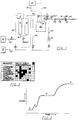
- Figure 1 is a schematic diagram of an apparatus according to the present invention.
- Figure 2 is a graphic presentation of sequencing of the valving depicted of Fig. 1.
- Figure 3 is a graph of signal output from a detector depicted in Fig. 1.
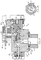
- Figure 4 is a side view in vertical section of a sample loading device according to the present invention.
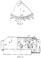
- Figure 5 is a top view of the device of Fig. 4.
- Figure 6 is a top view of a magazine utilized with the device of Fig. 4.
- Figure 7 is a side view in vertical section of a gas mixing vessel according to the present invention.
- Figure 1 shows a block diagram of an apparatus for combusting a sample and quantitatively analyzing the gaseous mixture of combustion products for its components, according to the present invention.
- the apparatus includes a sample loader 12 located above a combustion furnace 14 for loading a test sample into the furnace.
- the sample may be in the form of a pellet, a sample enclosed in tin foil or the like or other convenient form.
- the furnace is maintained at about 950°C.
- Oxygen is introduced into furnace 14 under pressure from an oxygen source 16 through a line 33 , an opened valve B and a gas line 32 . Ignition occurs at the furnace temperature. Combustion products are passed over catalytic agents in the lower portion of the furnace and thence through a line 34 to a reduction oven 18 at 650°C containing copper to reduce oxides of nitrogen and remove all excess oxygen. At this stage the combustion products typically consist of water, carbon dioxide and nitrogen.
- the gaseous combustion products are then partially mixed with and forced under the pressure of an inert carrier gas such as helium or argon, from a source 19 via line 37 and opened valve A and line 32 , through line 35 ,valve D and line 36 into an enclosed sample vessel 20 .
- an inert carrier gas such as helium or argon
- a pressure transducer 22 on sample vessel 20 detects when the preselected pressure is reached and generates an electrical signal which, through a controller 23 and electrical lines 50 , 50 ′ (shown dashed to distinguish from gas lines) closes carrier valve A and inlet valve D.
- valve G is opened and the mixture is forced by its elevated pressure into and through a tubular column 24 via a line 38 .
- the tubular column is conveniently a coiled length of tubing.
- Adsorbent material 26 in the column selectively determines the rate of passage of the individual combustion products in the gas mixture.
- the time variant gas composition then passes through a line 40 and into a sample chamber 28 containing a detector 30 that measures a physical property of the gas mixture that depends on its composition.
- the detector is a thermistor, measuring thermal conductivity.
- the mixture is subsequently vented through a line 42 to atmosphere.
- FIG. 2 shows the sequence of steps and the associated valve positions of the valves indicated in Fig. 1.
- valve C feeding the inert carrier gas through a constrictor 31 and a gas line 44 is open and the helium is used to purge column 24 and sample vessel 20 .
- valves D, E and F are also open for purging and the next step. This purging is maintained during all subsequent steps except analysis as described below.
- valve H is opened to vent the furnace 14 and oven 18 .
- various valves are set for purging the entire system with helium, as indicated in Fig. 2 with continuing reference to Fig. 1.
- vessel 20 receives helium from valve F via a line 46 and is vented via line 36 and valve E.
- Oxygen is then introduced into furnace 14 with valve B and vent valve H both open, while valves A and D are closed and the helium continues purging the rest of the system.
- Figure 3 shows the type of signal output to be expected from the detector during the time period of the analysis step.
- the signal reflects the property of the pure carrier gas.
- Q represents the mixture of the most mobile component (e.g. nitrogen) and carrier.
- R represents this mixture plus the next most mobile component (e.g. CO2).
- S represents the mixture of all the components which can traverse the column (e.g. carrier plus N2, CO2 and H2O).
- Column 24 is formed as a coiled length of tubing of stainless steel. It should be between 10 and 100 cm in length, preferably between 30 and 90 cm, for example 60 cm. The inside diameter is between 1 and 4 mm, preferably 1.5 and 2.5 mm, for example 2 mm.
- the adsorbent material 26 in the column is , for example, a porous polymer such as 80/100 mesh "Porapak" sold by Waters Associates.
- the single tubular column 24 containing adsorbent 26 replaces a number of components used heretofore, namely a sample volume and two separate sample traps and multiple detector cells for removing and detecting individual gas components in sequence. Accuracy and speed are also obtained by the fact that baseline measurements are made during the analysis stage, replacing a separate two-minute baseline run that was necessary in the past. Advantages include the economy and gas circuit simplification afforded by a single detector cell over the multiple cell configuration of Condon and complexities of Rezl.
- the column is "regenerated" by purging with carrier gas whereas absorbing traps must be refilled periodically. Further improvements in speed and accuracy are effected through the use of certain other components according to the present invention, as described below.
- FIG. 4 A rapidly operating sample loading device 12 that adds a minimum of volume to the system is shown in Fig. 4.
- An elongated body 52 has a piston end 54 , a body chamber generally comprising a central chamber 56 and a cylindrical cavity 58 extending generally horizontally from chamber 56 to piston end 54 , a body aperture 60 extending from cylindrical cavity 58 proximate chamber 56 upwardly through the body, and a drop port 62 extending from chamber 56 downwardly through the body.
- Body aperture 60 is receptive of a sample 64 from above which is passed downwardly through port 134 in block 132 .
- a piston member 66 is slidingly situated in cylindrical cavity 58 such as to have an inner position adjacent to chamber 56 and an outer position away from the chamber; Fig. 4 shows the piston at the outer position.
- a guide member 68 is attached to the inner end 70 of piston 66 such as to protrude into chamber 56 .
- Guide member 68 has a vertical guide aperture 71 therethrough that is alternatively aligned vertically with body aperture 60 (as shown) to receive sample 64 when piston 66 is at the outer position, or with drop port 62 when the piston is at the inner position.
- a horizontally sliding sample-retaining door 72 is situated adjacently below guide member 68 and has a wall portion 74 for retaining sample 64 , and a door aperture 76 adjacent to the wall portion extending vertically through the retaining door.
- the retaining door has a "T" shaped cross section and is slidingly supported in a track 78 in the underside of guide member 68 .
- Wall portion 74 (Fig. 4) is located between door aperture 76 and piston 66 .
- Retaining door 72 is positioned alternatively in a sample retaining position (shown in Fig.
- each such position being with respect to guide member 68 such that wall portion 74 is aligned vertically with guide aperture 71 for the retaining position, and door aperture 76 is aligned vertically with guide aperture 71 for the drop position.
- a compressed spring 84 is positioned from a first hole 86 in piston 66 to a second hole 88 in door 72 .
- Spring 84 presses mating surface 82 against a positioning pin 80 in a direction away from piston 66 such that retaining door 72 is normally maintained in the retaining position shown in Fig. 4 by the spring.
- a door actuator 90 is used for sliding retaining door 72 to the drop position while piston 66 is at its forward position, thereby releasing sample 64 through door aperture 76 and thence through drop port 62 .
- a retractable actuator rod 92 extends loosely through a bore 94 in body 52 extending from chamber 56 in a direction generally parallel to and away from cylindrical cavity 58 , rod 92 having an extended axis 96 which intersects retaining door 72 .
- rod 92 can be pushed against retaining door 72 to retract the door against spring 84 to the drop position and align door aperture 76 between guide aperture 71 and drop port 62 , thus dropping sample 64 out of the loading device.
- Piston 66 and actuator rod 92 may each be moved by hand or a solenoid, motor or the like, but pneumatic linear actuators of the known or desired type are desirable for each of these functions.
- a piston actuator 98 is mounted to body 52 with a spacer bracket 100
- a rod actuator 102 is mounted to the body with a mounting collar 104 . (Mounting screws are not shown.)
- Sample-receiving furnace 14 is sealed with an O-ring 103 under body 52 below the drop port, affording a minimum of internal volume, by screws 105 through a flange 107 on the furnace.
- Mounting collar 104 is coaxial with bore 94 and is sealed between body 52 and actuator 102 with O-ring seals 106 .
- An O-ring 108 seals an actuator flange 110 against rod 92 and allows the rod to slide therein, thus effectively providing sealing between the movable rod and the body.
- An annular cavity 112 is formed between collar 104 and rod 92 .
- Means is provided for sealing the chamber with the piston when the piston is at its forward position.
- Inner end 70 of piston 66 has a peripheral annular surface 114 perpendicular to the common axis of the piston and cylindrical cavity 58 .
- the cylindrical cavity is bounded at the chamber by a second annular surface 116 that is parallel to and facing first surface 114 in alignment therewith.
- An O-ring seal 118 in an annular groove 120 in annular surface 114 (or in the second annular surface) effects a seal between chamber 56 and cavity 58 when piston 66 is at the forward position.
- a gas inlet orifice 122 is provided for introducing oxygen and, as required, helium (or argon) into the chamber, via gas line 32 (Fig. 1), annular cavity 112 and bore 94 , when piston 66 is at the inner position at which time chamber 56 is fully sealed from the ambient atmosphere except for the drop port 62 entrance to furnace 14 .
- a magazine loader 130 is mounted above body 52 for loading successive samples into body aperture 60 .
- the magazine loader shown in top view in Fig. 5, as well as in Fig. 4, comprises a loading member 132 slidingly mounted on top of the body.
- the loading member has a vertical loading aperture 134 therethrough that is receptive of the next sample from above when loading member 132 is in a forward position (indicated by dashed line 133 ).
- loading aperture 134 is alignable with body aperture 60 to drop the next sample therethrough.
- a disk shaped magazine 136 a portion of which is also depicted in top view in Fig. 6, is mounted on an axle 137 and is positioned above loading member 132 .
- the magazine has a plurality of equally spaced vertical magazine cavities 138 therethrough, the cavities being positioned arcuately near the rim 140 of the magazine disk. Each cavity (that has not yet supplied a sample) holds at least one of a plurality of samples 142 .
- the magazine has successive loading positions and is movable to each of the successive loading positions.
- a ring-shaped mounting plate 144 of outer diameter comparable to that of magazine 136 is fixed with respect to body 52 and is juxtaposed closely between sample magazine 136 and loading member 132 to retain the plurality of samples 142 in the respective magazine cavities 138 .
- a plate opening 146 extends vertically through mounting plate 144 and is located with respect to the magazine to pass a sample through from an adjacent magazine cavity 138 ′, the magazine being in a loading position. Plate opening 146 is oriented vertically above aperture 134 when loading member 132 is in its forward position 133 . When member 132 is retracted, a sample received through opening 146 is dropped through aperture 60 .
- Body 52 has an elongated pin opening 148 extending upwardly therethrough from cylindrical cavity 58 .
- a pin 150 is threaded into piston 66 and extends radially upwards through pin opening 148 .
- Loading member 132 on top of body 52 has a pin orifice 152 therein that allows member 132 to be engaged by pin 150 .
- Figure 5 shows a top view of the loading device without magazine or plate.
- a slot 154 in member 132 cooperates with a retaining screw 156 threaded into the top of body 52 to guide the loading member.
- a drive pawl 154 is attached to the top of the loading member 132 with screws 156 (also in Fig. 5)
- Ratchet teeth 158 are equally positioned arcuately under magazine 136 near rim 140 (Fig. 6) but radially in from plate 144 , in actuating contact with the drive pawl.
- piston 66 Upon actuation of piston 66 from the outer position to the inner position pin 150 , after a free motion, slides the loading plate such that drive pawl 154 moves magazine 136 to a subsequent loading position to deposit a new sample through plate opening 146 and aperture 134 to rest on top of block 52 .
- piston 66 is returned to its outer position pin 150 moves loading member 132 back so the sample is dropped through loading aperture 134 and body aperture 60 .
- the new sample is being loaded into the device while the previous sample 64 is being dropped into furnace 14 .
- the magazine has a separation distance "S" between each successive magazine cavity 138 and also between each ratchet tooth 158 (or a multiple number thereof) that is less than the travel distance "T” of piston 66 between the outer position and the inner position.
- Pin 150 has a diameter "P”.
- the pin is 9.5 mm in diameter
- the elongated dimension of the pin opening in the loading plate is 22 mm
- the travel distance of the piston is 25 mm
- the separation between cavities in the magazine is 11 mm and between ratchet teeth is 8 mm.
- a unique gas mixing vessel 20 is used for homogenizing the gases at a substantially constant temperature while the gases are being introduced into the vessel at increasing pressure.
- a sealable vessel 160 is constructed of a casing 162 which includes a cover 164 .
- a gas connection 166 receives the gaseous combustion products from line 36 under the pressure of the carrier gas.
- an impeller 168 mounted in the vessel stirs the gases.
- the impeller desirably has two (or more) blades 170 mounted with pins 171 on a shaft 172 that rotates in a ball bearing assembly 174 .
- Each blade preferably has a twisted "S" shape such as to impart an axial component to gas motion in the vessel to efficiently and rapidly mix the gases.
- each blade 170 is formed of a material with a relatively high mass with a corresponding heat capacity and a thermal conductivity that are sufficiently high to effectively maintain constant temperature of the gas mixture in vessel 160 during pressurization.
- the purpose is to counter the tendency for the gases to increase in temperature during the inlet pressurization process. It is desirable to pressurize at a rate 1 atmosphere within 10 seconds, and it is highly desirable to maintain the temperature within 0.5°C during gas input so that the volume of gas can be sent to the column as soon as mixing is completed, without waiting for the temperature to settle. Thus the cycling time for the analyses is further shortened.
- the total heat capacity (i.e. specific heat times total mass) of the blades should be at least 30 times the total heat capacity of the gases in the vessel at the predetermined pressure.
- Thermal conductivity of the blade material should be at least 2.1 Joule/sec °C cm (0.5 calories/sec °C cm)relative to 4.2 for pure copper. Copper is preferable, gold plated to minimize contamination. For example for a mixing vessel having a net volume (with impeller and associated components in place) of 300 cc, copper blades with a total mass of 35 gm is desirable.
- a PTFE plastic coated bar magnet 176 is mounted perpendicularly on shaft 172 inside vessel 160 proximate the lower end wall 178 of casing 162 .
- a horseshoe magnet 180 with poles 182 aiming upwards is set on a vertical shaft 184 aligned with the impeller axis 186 and is located below the vessel proximate end wall 178 .
- a motor 188 drives shaft 184 , and the outside magnet 180 is magnetically coupled to the inside magnet 170 for rotating same and thereby rotating blades 170 at high speed, probably between 1000 and 3000, e.g. about 1500 rpm.
- the gas connection components include valve D (and, as appropriate, valves E and G shown in Fig. 1) and tube section 36 connected between the valve and the vessel and, similarly, valve F and tube section 46 for a second gas connection 190 . It is important that the tube sections 36, 46 contribute only a very small volume to assure thorough mixing of the enclosed gases, e.g., less than 0.25% of the volume of vessel 160 containing impeller 168 , for example having a length of 30 cm each and an inside diameter of 1 mm.
- the top of the vessel casing comprises cover 164 held to a flange 192 with screws 194 and sealed against the flange with an O-ring seal 196 .
- the cover includes the gas tube connections 166, 190 .
- An opening 198 in cover 164 provides for a differential pressure transducer 200 held over the opening with a yoke 202 .
- the transducer may be of the conventional type, such as model P612 sold by Kavlico Corp., Chatsworth, California.
- the yoke is attached to the cover with screws 203 , and a thumb screw 204 presses the transducer against an elastomer face seal 206 on the cover.
- a buffer container 208 nominally at atmospheric pressure is connected via a tube 210 to the transducer to provide a control pressure unperturbed by short term fluctuations in ambient pressure.
- a vent valve 212 allows resetting the buffer pressure. The close proximity of transducer 200 to opening 198 in the vessel casing further minimizes extraneous volume for the mixing process.
- Transducer 200 is set to detect when the pressure from the input gases reaches a predetermined pressure, for example about one atmosphere above ambient and generally in the range of about half to 1.3 atmospheres. Referring also to Fig. 1, electrical signals through lines 50,50 ′ and controller 23 closes carrier gas inlet valves A and D when the vessel pressure reaches the predetermined pressure.
Landscapes
- Health & Medical Sciences (AREA)
- Chemical & Material Sciences (AREA)
- Life Sciences & Earth Sciences (AREA)
- Biochemistry (AREA)
- Combustion & Propulsion (AREA)
- Molecular Biology (AREA)
- Physics & Mathematics (AREA)
- Analytical Chemistry (AREA)
- Engineering & Computer Science (AREA)
- General Health & Medical Sciences (AREA)
- General Physics & Mathematics (AREA)
- Immunology (AREA)
- Pathology (AREA)
- Sampling And Sample Adjustment (AREA)
- Other Investigation Or Analysis Of Materials By Electrical Means (AREA)
- Investigating Or Analyzing Non-Biological Materials By The Use Of Chemical Means (AREA)
Claims (7)
- Vorrichtung zum quantitativen Analysieren einer gasförmigen Mischung bezüglich ihrer Bestandteile mit:
einer Volumenvorrichtung (20) zum Sammeln einer gasförmigen Mischung eines Grundstoffs und wenigstens einer zusätzlichen Komponente;
einer druckbeaufschlagten Fluidvorrichtung (19);
einer rohrförmigen, chromatographischen Säule (24) mit einem Einlaßende und einem Auslaßende, wobei das Einlaßende in fluidflußmäßiger Beziehung mit der Volumenvorrichtung steht;
einer Probenkammer (28), die in fluidflußmäßiger Beziehung mit dem Auslaßende der rohrförmigen Säule (24) steht;
einer Ventilvorrichtung (38) zum Entlassen eines Teils der Mischung aus der Volumenvorrichtung nacheinanderfolgend durch die Säule (24) und die Probenkammer (28) für eine bestimmte Zeitdauer, wobei die Mischung anfänglich sich bei einem vorausgewählten Druck in der Volumenvorrichtung befindet;
einer Extraktionsvorrichtung (26), die in der Säule (24) vorgesehen ist, zum Extrahieren einer vorbestimmten Menge einer jeden zusätzlichen Komponente von der Mischung, um somit eine zeitlich veränderliche Zusammensetzung der Mischung in der Probenkammer während der vorbestimmten Zeitdauer zu erzeugen;
einer Komponentennachweisvorrichtung (30), die aus einem einzigen Detektor besteht, der mit der Probenkammer (28) in Verbindung steht, zum Nachweisen einer physikalischen Eigenschaft der Mischung in Abhängigkeit von der zeitlich veränderlichen Zusammensetzung, um somit ein Maß für die Menge einer jeden zusätzlichen Komponente in der gasförmigen Mischung in der Probenkammer (28) während der vorbestimmten Zeitdauer zu schaffen;
einer Verbrennungsvorrichtung zum aufeinanderfolgenden Verbrennen jeder Testprobe aus einer Vielzahl von Testproben, um als Verbrennungsprodukte wenigstens eine Komponente der gasförmigen Mischung zu erzeugen, wobei die Verbrennungsvorrichtung einen Verbrennungsofen (14), ein Magazin (136) zum Halten der Vielzahl von Testproben, eine Transfervorrichtung (12), die mit dem Verbrennungsofen (14) in Verbindung steht, zum nacheinanderfolgenden Übertragen einer nachfolgenden Probe von dem Magazin (136) zu dem Verbrennungsofen 14), und eine mit der Transfervorrichtung (12) integrale Verbrennungsofendichtvorrichtung umfaßt zum zeitweiligen Abdichten des Verbrennungsofens von der Umgebungsatmophäre, nachdem die Probe zu dem Verbrennungsofen (14) übertragen worden ist, bis zur nachfolgenden Übertragung; und
einer Vorrichtung (122) zum Einspeisen von Sauerstoff in den Verbrennungsofen (14);
dadurch gekennzeichnet, daß
die Volumenvorrichtung (20) einen Behälter mit festem Volumen umfaßt, der mit der druckbeaufschlagten Fluidvorrichtung in Verbindung steht, die geeignet ausgebildet ist, die gasförmige Mischung der Grundstoffkomponente in den Behälter bis zu einem vorausgewählten Druck zu treiben;
und daß die Transfervorrichtung (12) umfaßt:
einen Körper (52) mit einem Fallabschnitt, einem Kolbenende (54), einer darin befindlichen Körperkammer (56), die sich horizontal von dem Fallabschnitt zu dem Kolbenende (54) erstreckt, einer Körperöffnung (60), die sich von der Körperkammer (56) nach oben durch den Körper (52) erstreckt, um so die Probe aufnehmen zu können, und einem Fallkanal (62) in dem Fallabschnitt, der sich nach unten durch den Körper (52) von einem Punkt in der Körperkammer, der senkrecht zu der Körperöffnung (60) versetzt ist, erstreckt;
ein Kolbenteil (66), das verschiebbar in der Körperkammer (56) angeordnet ist, so daß es eine erste Position und eine zweite Position einnehmen kann;
eine Führungsvorrichtung (68) zum Führen der Probe, die mit dem Kolbenteil (66) zusammenwirkt, um die Probe von der Körperöffnung (60) aufnehmen zu können, wenn das Kolbenteil (66) sich an der ersten Position befindet, und um senkrecht mit dem Fallkanal (62) ausgerichtet zu sein, wenn der Kolben (66) sich an der zweiten Position befindet;
eine Rückhaltevorrichtung (88) zum zeitweiligen Zurückhalten der Probe in der Führungsvorrichtung (68); und
eine Freigebevorrichtung (92) zum Freigeben der Probe aus der Führungsvorrichtung (68) durch den Fallkanal (62). - Vorrichtung gemäß Anspruch 1, wobei die Verbrennungsofendichtvorrichtung eine Kolbendichtvorrichtung enthält zum Bewirken einer Abdichtung zwischen dem Kolbenteil (66) und wenigstens einem Teil der Körperkammer (56), wenn das Kolbenteil (66) sich an einer vorausgewählten Position in der Körperkammer (56) befindet.
- Vorrichtung nach Anspruch 1, wobei die druckbeaufschlagte Fluidvorrichtung geeignet ausgebildet ist zur Einspeisung der Vielzahl von Gasen in den Behälter bei sich erhöhendem Druck in dem Behälter bis zu einem vorbestimmten Druck, wobei die Vorrichtung weiter ein Gasmischsystem umfaßt zum Homogenisieren des vorbestimmten Volumens der gasförmigen Mischung bei einer im wesentlichen konstanten Temperatur mit einer Flügelradvorrichtung (168), die drehbar in dem Behälter zum Rühren der Gase angebracht ist, und mit einer Drehvorrichtung zum Drehen des Flügelrads (168) mit hoher Geschwindigkeit, wobei die Flügelradvorrichtung (168) eine Vielzahl von Flügeln (170) umfaßt, die jeweils aus einem Material mit einer derartigen Masse gebildet sind, daß die gesamte Wärmekapazität der Flügel und die thermische Leitfähigkeit des Flügelmaterials in Zusammenwirkung mit der Drehung des Flügelrads die Temperatur auf 1°C während der Einspeisung der Gase bei einer Rate von 1 Atmosphäre in 10 Sekunden aufrechterhalten, während die Gase bei hoher Geschwindigkeit umgerührt werden.
- Vorrichtung nach Anspruch 3, wobei die gesamte Wärmekapazität der Flügel (170) wenigstens das 30-fache der gesamten Wärmekapazität der Gase in dem Behälter bei dem vorbestimmten Druck beträgt und die thermische Leitfähigkeit wenigstens 2,1 Joule/Sekunde °C cm relativ zu 4,2 für reines Kupfer beträgt.
- Vorrichtung gemäß Anspruch 3, wobei der Behälter eine Abschlußwand (178) aufweist, wobei die Flügelradvorrichtung (168) weiter eine axiale Welle (172) umfaßt, an der die Flügel (170) angebracht sind, wobei die Drehvorrichtung einen innenliegenden Magneten (176) umfaßt, der an der Welle in der Nähe der Abschlußwand (178) angebracht ist, und wobei das System weiter eine Drehmagnetvorrichtung (180) umfaßt, die außerhalb des Behälters in der Nähe der Abschlußwand angeordnet ist und magnetisch mit dem innenliegenden Magneten (176) gekoppelt ist, um denselben zu drehen und dadurch die Flügel zu drehen.
- Vorrichtung gemäß Anspruch 3, wobei die Gasvorrichtung ein Ventil (D) und eine Leitung (36) umfaßt, die das Ventil und den Behälter verbindet, wobei die Leitung ein Volumen aufweist, das kleiner als 1 % des Volumens des die Flügelradvorrichtung enthaltenden Behälters ist.
- Vorrichtung gemäß Anspruch 3, die weiter eine Fühlervorrichtung (200) umfaßt zum Fühlen des Drucks in dem Behälter, wobei der Behälter aus einem Gehäuse gebildet ist, wobei die Fühlervorrichtung (200) in der Nähe des Gehäuses angeordnet ist, und wobei die Gasvorrichtung ein Ventil umfaßt, das die Vielzahl von Gasen empfängt, eine offene Stellung zum Einspeisen der Gase in den Behälter aufweist und auf die Fühlervorrichtung anspricht, so daß es geschlossen wird, wenn der Behälterdruck den vorbestimmten Druck erreicht.
Applications Claiming Priority (2)
| Application Number | Priority Date | Filing Date | Title |
|---|---|---|---|
| US07/019,905 US4795614A (en) | 1987-02-27 | 1987-02-27 | Apparatus for analysis of organic material |
| US19905 | 1987-02-27 |
Publications (3)
| Publication Number | Publication Date |
|---|---|
| EP0280335A2 EP0280335A2 (de) | 1988-08-31 |
| EP0280335A3 EP0280335A3 (en) | 1990-07-18 |
| EP0280335B1 true EP0280335B1 (de) | 1995-07-26 |
Family
ID=21795679
Family Applications (1)
| Application Number | Title | Priority Date | Filing Date |
|---|---|---|---|
| EP88102940A Expired - Lifetime EP0280335B1 (de) | 1987-02-27 | 1988-02-26 | Analyse von organischen Substanzen |
Country Status (4)
| Country | Link |
|---|---|
| US (1) | US4795614A (de) |
| EP (1) | EP0280335B1 (de) |
| JP (3) | JP2683011B2 (de) |
| DE (1) | DE3854209T2 (de) |
Families Citing this family (17)
| Publication number | Priority date | Publication date | Assignee | Title |
|---|---|---|---|---|
| US5013528A (en) * | 1987-02-27 | 1991-05-07 | The Perkin-Elmer Corporation | Analysis of organic material |
| US5571478A (en) * | 1990-10-22 | 1996-11-05 | Marine Shale Processors, Inc. | Method and system for determining the destruction and removal efficiency of a thermal combustion device |
| US5476637A (en) * | 1992-04-09 | 1995-12-19 | Hans-Dieter Schultz | Method and device for the, measurement of impurities in a liquid more particularly water |
| US6821773B1 (en) | 1992-07-09 | 2004-11-23 | Nl Technologies, Ltd. | Drainable ferrule valve design |
| IT1256356B (it) * | 1992-08-31 | 1995-12-01 | Dispositivo per l'alimentazione di campioni ad apparecchiature di analisi elementare | |
| ITTO20010175U1 (it) * | 2001-09-19 | 2003-03-19 | Eurovector S P A | Campionatore, particolarmente per analizzatori elementari automatici. |
| ITTO20010895A1 (it) * | 2001-09-19 | 2003-03-19 | Eurovector S P A | Dispositivo campionatore, particolarmente per analizzatori elementariautomatici. |
| DE10203310A1 (de) * | 2002-01-29 | 2003-07-31 | Daimler Chrysler Ag | Probenahmesystem für Abgassensoren |
| JP4163123B2 (ja) * | 2002-03-15 | 2008-10-08 | カーネギー インスチチューション オブ ワシントン | 自動試料取扱装置の回転ラック |
| NL1023809C2 (nl) * | 2003-07-03 | 2005-01-04 | Thermo Euroglas B V | Werkwijze voor het analyseren van een monster en analyse-inrichting. |
| CN109030707A (zh) * | 2018-07-13 | 2018-12-18 | 哈尔滨锅炉厂有限责任公司 | 微量煤粉燃烧挥发分释放及氮分布特性可控高温反应系统 |
| JP6989484B2 (ja) | 2018-12-20 | 2022-01-05 | 株式会社堀場製作所 | 試料前処理装置及び分析システム |
| CN113117381B (zh) * | 2021-04-17 | 2022-05-17 | 宁波海关技术中心 | 一种快速固相萃取仪器 |
| CN116298026A (zh) * | 2023-03-30 | 2023-06-23 | 河北地质大学 | 一种连续进样层析装置及其进样控制方法 |
| CN116077986B (zh) * | 2023-04-07 | 2023-06-02 | 广东汇群中药饮片股份有限公司 | 基于空化作用的萃取装置及在制备余甘子枇杷膏中的应用 |
| KR102954504B1 (ko) * | 2023-05-19 | 2026-04-17 | 현대제철 주식회사 | 환원로 및 이를 이용한 원료 환원방법 |
| CN121090758A (zh) * | 2025-11-06 | 2025-12-09 | 东营市工业产品检验与计量检定中心 | 一种高分子耐火阻燃材料的性能检测装置 |
Family Cites Families (20)
| Publication number | Priority date | Publication date | Assignee | Title |
|---|---|---|---|---|
| US2576802A (en) * | 1948-11-15 | 1951-11-27 | Janet C Morris | Food chopping attachment |
| US2556854A (en) * | 1949-10-29 | 1951-06-12 | Standard Oil Dev Co | Magnetic coupling drive for highpressure stirred reactors |
| US2859020A (en) * | 1955-11-10 | 1958-11-04 | Phillips Petroleum Co | Magnetic driven collapsible agitator assembly |
| US2837320A (en) * | 1956-04-27 | 1958-06-03 | Howard C Baron | Magnetic mixers |
| US3168294A (en) * | 1960-08-15 | 1965-02-02 | Hasumura Tadashi | Mixing apparatus wherein magnets are utilized |
| NL285213A (de) * | 1961-11-09 | |||
| CH431139A (de) * | 1965-01-19 | 1967-02-28 | Bayer Ag | Pyrolyse- und Reaktionskammer für Gaschromatographie |
| US3698869A (en) * | 1965-08-20 | 1972-10-17 | Perkin Elmer Corp | Analysis of gaseous mixtures |
| GB1170535A (en) * | 1967-04-19 | 1969-11-12 | Ass Elect Ind | Improvements in or relating to means for Feeding Specimens into Evacuated Chambers |
| US3911723A (en) * | 1974-08-08 | 1975-10-14 | Us Commerce | Exponential dilution flask |
| US4055259A (en) * | 1976-03-03 | 1977-10-25 | The Perkin-Elmer Corporation | Sample transport with rotary air interlock charging and discharging means |
| CH627845A5 (de) * | 1977-12-27 | 1982-01-29 | Groeninger Kurd | Vorrichtung zur zeitlichen verkuerzung eines wasserdampf-sorptionsprozesses. |
| JPS564052A (en) * | 1979-06-23 | 1981-01-16 | Yanagimoto Seisakusho:Kk | Concentration measuring device for nonmethane organic compound |
| JPS57132058A (en) * | 1981-02-07 | 1982-08-16 | Gasukuro Kogyo Kk | Sampling system |
| JPS6339646Y2 (de) * | 1981-03-30 | 1988-10-18 | ||
| JPS5830870U (ja) * | 1981-08-25 | 1983-02-28 | 三菱重工業株式会社 | 計量管 |
| US4525328A (en) * | 1982-03-05 | 1985-06-25 | Leco Corporation | Carbon, hydrogen, and nitrogen analyzer |
| US4496249A (en) * | 1982-09-23 | 1985-01-29 | University Of Florida | Method and apparatus for determining relative surface areas of a coated material on a substrate |
| JPS61194366A (ja) * | 1985-02-25 | 1986-08-28 | Nippon Kokan Kk <Nkk> | 分析試料用トレ−の自動式電気炉插入、抽出装置 |
| JPS6291692A (ja) * | 1985-10-16 | 1987-04-27 | Ngk Insulators Ltd | 回転機器用マグネツト駆動装置 |
-
1987
- 1987-02-27 US US07/019,905 patent/US4795614A/en not_active Expired - Lifetime
-
1988
- 1988-02-26 JP JP63042431A patent/JP2683011B2/ja not_active Expired - Lifetime
- 1988-02-26 EP EP88102940A patent/EP0280335B1/de not_active Expired - Lifetime
- 1988-02-26 DE DE3854209T patent/DE3854209T2/de not_active Expired - Fee Related
-
1997
- 1997-01-16 JP JP9005619A patent/JP2730624B2/ja not_active Expired - Lifetime
- 1997-01-16 JP JP9005622A patent/JP2786435B2/ja not_active Expired - Lifetime
Also Published As
| Publication number | Publication date |
|---|---|
| JP2786435B2 (ja) | 1998-08-13 |
| EP0280335A3 (en) | 1990-07-18 |
| JP2683011B2 (ja) | 1997-11-26 |
| DE3854209D1 (de) | 1995-08-31 |
| US4795614A (en) | 1989-01-03 |
| JPH09184828A (ja) | 1997-07-15 |
| JPS63265165A (ja) | 1988-11-01 |
| JP2730624B2 (ja) | 1998-03-25 |
| DE3854209T2 (de) | 1995-12-07 |
| EP0280335A2 (de) | 1988-08-31 |
| JPH09196827A (ja) | 1997-07-31 |
Similar Documents
| Publication | Publication Date | Title |
|---|---|---|
| US4795614A (en) | Apparatus for analysis of organic material | |
| US5792423A (en) | Headspace autosampler apparatus and method | |
| US5441700A (en) | Headspace autosampler apparatus | |
| US5932482A (en) | Headspace vial apparatus and method | |
| US5822951A (en) | Apparatus and method for sampling gas in product packages | |
| JP6151764B2 (ja) | クロマトグラフィ分離方法のためのサンプルを調製するための方法及びサンプル調製を実行するためのデバイス | |
| JPH05506096A (ja) | 分析装置の移送装置 | |
| EP0729577B1 (de) | Verfahren zur isotopenzusammensetzungsanalyse und isotopenzusammensetzungsanalysator | |
| US4113434A (en) | Method and apparatus for collectively sampling a plurality of gaseous phases in desired proportions for gas analysis or other purposes | |
| US3249403A (en) | Liquid sample reactor and evolved gas detector | |
| US4055259A (en) | Sample transport with rotary air interlock charging and discharging means | |
| JPH11211630A (ja) | ガス試料捕集装置及びその使用方法 | |
| JP4361936B2 (ja) | サンプル容器内へと標準ガスを導入するための方法 | |
| US5044860A (en) | Analysis of organic material | |
| CN114088962A (zh) | 一种高通量小样品量土壤微生物呼吸气体进样装置 | |
| US5013528A (en) | Analysis of organic material | |
| CN115684434B (zh) | 一种处理环境空气样品和液体样品的前处理一体机 | |
| US4837374A (en) | Microreactor for analyzing thin solid samples | |
| JPH0115810B2 (de) | ||
| US3898041A (en) | Fluid sampler apparatus and method | |
| CN118730942A (zh) | 一种铜合金切削液制备用浓度检测装置 | |
| CN218331388U (zh) | 一种处理环境空气样品和液体样品的前处理一体机 | |
| Leinster et al. | Detection and measurement of volatile hydrocarbons at ambient concentrations in the atmosphere | |
| US20050064597A1 (en) | Sampling device for automatic elemental analysers | |
| CN221332874U (zh) | 在线自动化固相微萃取装置 |
Legal Events
| Date | Code | Title | Description |
|---|---|---|---|
| PUAI | Public reference made under article 153(3) epc to a published international application that has entered the european phase |
Free format text: ORIGINAL CODE: 0009012 |
|
| AK | Designated contracting states |
Kind code of ref document: A2 Designated state(s): DE GB IT |
|
| PUAL | Search report despatched |
Free format text: ORIGINAL CODE: 0009013 |
|
| AK | Designated contracting states |
Kind code of ref document: A3 Designated state(s): DE GB IT |
|
| 17P | Request for examination filed |
Effective date: 19910118 |
|
| 17Q | First examination report despatched |
Effective date: 19931018 |
|
| GRAA | (expected) grant |
Free format text: ORIGINAL CODE: 0009210 |
|
| AK | Designated contracting states |
Kind code of ref document: B1 Designated state(s): DE GB IT |
|
| ITF | It: translation for a ep patent filed | ||
| REF | Corresponds to: |
Ref document number: 3854209 Country of ref document: DE Date of ref document: 19950831 |
|
| PLBE | No opposition filed within time limit |
Free format text: ORIGINAL CODE: 0009261 |
|
| STAA | Information on the status of an ep patent application or granted ep patent |
Free format text: STATUS: NO OPPOSITION FILED WITHIN TIME LIMIT |
|
| 26N | No opposition filed | ||
| REG | Reference to a national code |
Ref country code: GB Ref legal event code: IF02 |
|
| PGFP | Annual fee paid to national office [announced via postgrant information from national office to epo] |
Ref country code: GB Payment date: 20020220 Year of fee payment: 15 |
|
| PGFP | Annual fee paid to national office [announced via postgrant information from national office to epo] |
Ref country code: DE Payment date: 20020228 Year of fee payment: 15 |
|
| PG25 | Lapsed in a contracting state [announced via postgrant information from national office to epo] |
Ref country code: GB Free format text: LAPSE BECAUSE OF NON-PAYMENT OF DUE FEES Effective date: 20030226 |
|
| PG25 | Lapsed in a contracting state [announced via postgrant information from national office to epo] |
Ref country code: DE Free format text: LAPSE BECAUSE OF NON-PAYMENT OF DUE FEES Effective date: 20030902 |
|
| GBPC | Gb: european patent ceased through non-payment of renewal fee | ||
| PG25 | Lapsed in a contracting state [announced via postgrant information from national office to epo] |
Ref country code: IT Free format text: LAPSE BECAUSE OF NON-PAYMENT OF DUE FEES;WARNING: LAPSES OF ITALIAN PATENTS WITH EFFECTIVE DATE BEFORE 2007 MAY HAVE OCCURRED AT ANY TIME BEFORE 2007. THE CORRECT EFFECTIVE DATE MAY BE DIFFERENT FROM THE ONE RECORDED. Effective date: 20050226 |