EP0280365B1 - Klapperschutzführung für die voreingestellte Verteilereinheit von Verbrennungskraftmaschinen - Google Patents
Klapperschutzführung für die voreingestellte Verteilereinheit von Verbrennungskraftmaschinen Download PDFInfo
- Publication number
- EP0280365B1 EP0280365B1 EP88200286A EP88200286A EP0280365B1 EP 0280365 B1 EP0280365 B1 EP 0280365B1 EP 88200286 A EP88200286 A EP 88200286A EP 88200286 A EP88200286 A EP 88200286A EP 0280365 B1 EP0280365 B1 EP 0280365B1
- Authority
- EP
- European Patent Office
- Prior art keywords
- runner
- runners
- flapping
- transmission chain
- sprocket wheels
- Prior art date
- Legal status (The legal status is an assumption and is not a legal conclusion. Google has not performed a legal analysis and makes no representation as to the accuracy of the status listed.)
- Expired - Lifetime
Links
Images


Classifications
-
- F—MECHANICAL ENGINEERING; LIGHTING; HEATING; WEAPONS; BLASTING
- F16—ENGINEERING ELEMENTS AND UNITS; GENERAL MEASURES FOR PRODUCING AND MAINTAINING EFFECTIVE FUNCTIONING OF MACHINES OR INSTALLATIONS; THERMAL INSULATION IN GENERAL
- F16H—GEARING
- F16H7/00—Gearings for conveying rotary motion by endless flexible members
- F16H7/24—Equipment for mounting belts, ropes, or chains
-
- F—MECHANICAL ENGINEERING; LIGHTING; HEATING; WEAPONS; BLASTING
- F01—MACHINES OR ENGINES IN GENERAL; ENGINE PLANTS IN GENERAL; STEAM ENGINES
- F01L—CYCLICALLY OPERATING VALVES FOR MACHINES OR ENGINES
- F01L1/00—Valve-gear or valve arrangements, e.g. lift-valve gear
- F01L1/02—Valve drive
-
- F—MECHANICAL ENGINEERING; LIGHTING; HEATING; WEAPONS; BLASTING
- F01—MACHINES OR ENGINES IN GENERAL; ENGINE PLANTS IN GENERAL; STEAM ENGINES
- F01L—CYCLICALLY OPERATING VALVES FOR MACHINES OR ENGINES
- F01L1/00—Valve-gear or valve arrangements, e.g. lift-valve gear
- F01L1/02—Valve drive
- F01L1/022—Chain drive
-
- F—MECHANICAL ENGINEERING; LIGHTING; HEATING; WEAPONS; BLASTING
- F16—ENGINEERING ELEMENTS AND UNITS; GENERAL MEASURES FOR PRODUCING AND MAINTAINING EFFECTIVE FUNCTIONING OF MACHINES OR INSTALLATIONS; THERMAL INSULATION IN GENERAL
- F16H—GEARING
- F16H7/00—Gearings for conveying rotary motion by endless flexible members
- F16H7/18—Means for guiding or supporting belts, ropes, or chains
-
- F—MECHANICAL ENGINEERING; LIGHTING; HEATING; WEAPONS; BLASTING
- F02—COMBUSTION ENGINES; HOT-GAS OR COMBUSTION-PRODUCT ENGINE PLANTS
- F02B—INTERNAL-COMBUSTION PISTON ENGINES; COMBUSTION ENGINES IN GENERAL
- F02B2275/00—Other engines, components or details, not provided for in other groups of this subclass
- F02B2275/08—Endless member is a chain
Definitions
- the present invention relates to a flapping-preventing runner for a pre-timed distribution assembly for internal combustion engines.
- Distribution assemblies of internal combustion engines are substantially constituted by a pair of sprocket wheels connected to rotate in phase by a transmission chain, of single-link or multiple-link type, according to the size of the engine.
- a runner for tightening the transmission chain of such distribution assemblies is known, as disclosed in GB-A-2.092.705 which, summarizing, is constituted by a hub integral with a plate member defining at one of its flat sides two diverging guides destined to contain the two branches of the transmission chain of the distribution assembly. Said runner, although achieves the purposes it aims at, suffers from some drawbacks.
- Said runner does not make it possible to carry out a timed pre-assemblage of the distribution assembly and hence it renders the operation of assemblage of the same distribution assembly on the engine substantially complex.
- the purpose of the present invention is to provide a runner for a distribution assembly, having an extremely small lateral overall dimension, and capable of enabling a timed pre-assemblage of the distribution assembly to be carried out.
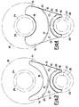
- the runner of the present invention is associated to a distribution assembly 18, comprising a larger sprocket wheel 19, a smaller sprocket wheel 20 and a transmission chain 21, and is constituted by a first half-runner 11 and a second half-runner 12 (showing a substantially "H"-shaped structure), which can be mutually joined side-to-side by means of traditional fastening means (not shown in the figures), engaging through-bores 13 provided in the half runners 11, 12.
- Both said half-runners 11 and 12 comprise a pair of divergent side edges 14 joined by two opposite positioning and centering arcuate edges 15 and 16, respectively of larger and smaller diameter. From the inner surface of each half-runner 11 and 12, a positioning and spacing projecting portion 17 protrudes which bears the means (bores 13) for the mutual joining of the half runners 11 and 12.
- each projecting portion 17 equals half thickness of the sprocket wheels 19 and 20 of the distribution assembly the runner 10 is designed to cooperate with.
- the portion 17 deliver pairs of arcuate edges 22 and 23, which are substantially respectively concentrical with the edges 15 and 16, respectively.
- the main difference existing between the first half-runner 11 and the second half-runner 12 is in the radius of the arcuate edge 15, which is considerably larger in the first half-runner 11.
- the arcuate edge 15 of the second half-runner 12 shows a substantially identical radius to that of an either stationary or movable sleeve 24 mounted on the shaft 25 of the sprocket wheel 19.
- the arcuate edges 16 of the half-runners 11 and 12 constitute positioning and centering portions cooperating with a sleeve 26 mounted on the drive shaft 27 of the sprocket wheel 20, or with other, similar, means, the arcuate edges 16 showing a radius substantially identical to that of the sleeve 26.
- the first half-runner 11 and the second half-runner 12 are joined together on an already timed distribution assembly 18 constituted by the pair of sprocket wheels 19 and 20 and the transmission chain 21.
- the runner 10 constitutes an integral body with the distribution assembly 18 which is traded in an already timed status, and ready for an extremely simplified application to the shafts 25 and 27 of the engine.
- the stability and functionality of the runner 10 are secured, first of all, by the presence of the divergent side edges 14, which support and guide the transmission chain 21 up to the first points of contact the same has with the sprocket wheels 19 and 20, and, secondly, by the contacts the edge 15 of the second half-runner 12, and the edges 16 of both half-runners 11 and 12 establish with the sleeves 24 and 26 on the distribution shaft 25 and drive shaft 27.
- the first step consists in positioning the sprocket wheels 19 and 20, timed relatively to each other, into engagement with the transmission chain 21.
- first half-runner 11 and the second half-runner 12 of the runner 10 are placed between the sprocket wheels 19 and 20 and are joined to each other, so that the two branches of the transmission chain 21 come to lay on the side edges 14.
- the distribution assembly 18 constitutes an integral body, because the side edges 14 guiding the transmission chain 21 on one side, and the arcuate edges 22 and 23 facing the sprocket wheels 19 and 20 on the other side, prevent, while respecting the necessary clearances for the assembly to correctly operate, the sprocket wheels 19 and 20 from taking a different timing to that as provided for at the time of assemblage of the whole distribution assembly.
- the so-preassembled assembly makes extremely easier the operation of assemblage thereof on the engine it is destined to.
Landscapes
- Engineering & Computer Science (AREA)
- General Engineering & Computer Science (AREA)
- Mechanical Engineering (AREA)
- Devices For Conveying Motion By Means Of Endless Flexible Members (AREA)
- Gears, Cams (AREA)
- Valve-Gear Or Valve Arrangements (AREA)
- Preparation Of Compounds By Using Micro-Organisms (AREA)
- Portable Nailing Machines And Staplers (AREA)
- Pistons, Piston Rings, And Cylinders (AREA)
Claims (3)
- Klapperschutzführung für eine voreingestellte Verteilereinheit von Verbrennungskraftmaschinen mit einem Paar von Zahnrädern (19,20, welche über eine Übertragungskette (21) rotierbar miteinander verbunden sind, dadurch gekennzeichnet, daß sie eine erste und eine Zweite Halbführung (11 bzw. 12) umfaßt, welche nebeneinander angeordnet sind, wobei jede Halbführung (11,12) von einer geformten Platte gebildet ist, welche gegenüberliegende, divergierende und die Kette abstützende Seitenkanten (14) aufweist, an welche gekrümmte Positionier- und Zentrierkanten (15,16) anschließen, wobei die gekrümmten Kanten (15,16) einer der Halbführungen einen Radius aufweisen, welcher im wesentlichen gleich dem Radius von an Wellen (25,27) angeordneten Buchsen (24,26) ist, wobei ein vorragender Bereich (17) zum Positionieren und Abstandhalten an der Innenfläche wenigstens einer Halbführung (11,12) vorgesehen ist, welche Mittel (Bohrungen 13) fur die gegenseitige Verbindung der Halbführungen (11,12) trägt, wobei der vorragende Bereich(17) mit zu den Zahnrädern (19,20) gewandten gekrümmten Kanten (22,23) ausgebildet ist.
- Klapperschutzführung nach Anspruch 1, dadurch gekennzeichnet, daß die verbundenen Halbführungen (11,12) Seitenabmessungen aufweisen, welche im wesentlichen innerhalb der Abmessungen der Zahnräder (19,20) und der Übertragungskette (21) liegen.
- Klapperschutzführung nach Anspruch 1, dadurch gekennzeichnet, daß die Halbführungen (11,12) Flansche (28) aufweisen, welche die zwischen den Zahnrädern (19,20) laufenden Teile der Übertragungskette (21) umgeben.
Priority Applications (1)
| Application Number | Priority Date | Filing Date | Title |
|---|---|---|---|
| AT88200286T ATE74653T1 (de) | 1987-02-23 | 1988-02-17 | Klapperschutzfuehrung fuer die voreingestellte verteilereinheit von verbrennungskraftmaschinen. |
Applications Claiming Priority (2)
| Application Number | Priority Date | Filing Date | Title |
|---|---|---|---|
| IT1945587 | 1987-02-23 | ||
| IT19455/87A IT1203337B (it) | 1987-02-23 | 1987-02-23 | Pattino antisbattimento per gruppo di distribuzione prefasato di motori a combustione interna |
Publications (3)
| Publication Number | Publication Date |
|---|---|
| EP0280365A2 EP0280365A2 (de) | 1988-08-31 |
| EP0280365A3 EP0280365A3 (en) | 1988-10-26 |
| EP0280365B1 true EP0280365B1 (de) | 1992-04-08 |
Family
ID=11158163
Family Applications (1)
| Application Number | Title | Priority Date | Filing Date |
|---|---|---|---|
| EP88200286A Expired - Lifetime EP0280365B1 (de) | 1987-02-23 | 1988-02-17 | Klapperschutzführung für die voreingestellte Verteilereinheit von Verbrennungskraftmaschinen |
Country Status (7)
| Country | Link |
|---|---|
| US (1) | US4850314A (de) |
| EP (1) | EP0280365B1 (de) |
| JP (1) | JP2680826B2 (de) |
| AT (1) | ATE74653T1 (de) |
| DE (1) | DE3869809D1 (de) |
| ES (1) | ES2030843T3 (de) |
| IT (1) | IT1203337B (de) |
Cited By (1)
| Publication number | Priority date | Publication date | Assignee | Title |
|---|---|---|---|---|
| US6955622B2 (en) | 2002-05-07 | 2005-10-18 | H. Winklhofer & Sohne Gmbh And Co. Kg | Preassembled drive means unit including a mounting aid |
Families Citing this family (19)
| Publication number | Priority date | Publication date | Assignee | Title |
|---|---|---|---|---|
| IT210738Z2 (it) * | 1987-06-02 | 1989-01-11 | Fiat Auto Spa | Dispositivo premontabile di trasmissione del moto tra assi paralleli |
| US4869708A (en) * | 1988-04-15 | 1989-09-26 | Borg-Warner Transmission And Engine Components Corporation | Sprocket retention/chain guide assembly |
| JP2563958Y2 (ja) * | 1993-08-30 | 1998-03-04 | 本田技研工業株式会社 | チェーンガイド装置 |
| DE19631875A1 (de) * | 1996-08-07 | 1998-02-12 | Bayerische Motoren Werke Ag | Kettentrieb-Einheit für eine Brennkraftmaschine |
| DE29621831U1 (de) * | 1996-12-16 | 1998-04-16 | Joh Winklhofer & Soehne Gmbh U | Vormontierte Zugmitteltriebeinheit |
| DE19831975A1 (de) * | 1997-12-05 | 1999-06-10 | Heidelberger Druckmasch Ag | Förderkette für einen ein Greifersystem tragenden Kettenförderer einer Druckmaschine |
| EP0947731B1 (de) * | 1998-03-31 | 2003-07-09 | Morse Tec Europe S.r.l. | Kettentrieb-Einheit mit einem Kettenspanner, insbesondere, jedoch nicht ausschliesslich, für Nockenwellenantriebe |
| JP4806825B2 (ja) * | 1999-04-07 | 2011-11-02 | シェフラー テクノロジーズ ゲゼルシャフト ミット ベシュレンクテル ハフツング ウント コンパニー コマンディートゲゼルシャフト | 変速機 |
| DE20120656U1 (de) | 2001-12-20 | 2003-04-30 | Joh. Winklhofer & Söhne GmbH und Co. KG, 81369 München | Vormontierte Triebmitteleinheit |
| NL1020535C2 (nl) * | 2002-05-03 | 2003-11-04 | Theodorus Henricus Johannes Carolina Korse | Kettingoverbrenging. |
| DE10318829B4 (de) * | 2003-04-25 | 2005-02-17 | Heckler & Koch Gmbh | Kettenabstreifer |
| ATE411485T1 (de) * | 2003-11-06 | 2008-10-15 | Bosch Gmbh Robert | Verfahren zum betrieb einer stufenlosen getriebevorrichtung |
| EP1963712A1 (de) * | 2005-12-13 | 2008-09-03 | LuK Lamellen und Kupplungsbau Beteiligungs KG | Führungsanordnung für ein umschlingungsmittel und spritzgusswerkzeug zur herstellung einer führungsanordnung |
| US8057336B2 (en) | 2005-12-13 | 2011-11-15 | Luk Lamellen Und Kupplungsbau Beteiligungs Kg | Guide device for an endless torque-transmitting means, and mold for producing a guide device |
| JP5464060B2 (ja) * | 2010-06-04 | 2014-04-09 | トヨタ自動車株式会社 | タイミングチェーンガイド装置 |
| WO2013154572A2 (en) * | 2012-04-13 | 2013-10-17 | The Gates Corporation | Timing belt spacer tool |
| DE102013211748A1 (de) * | 2012-07-17 | 2014-01-23 | Schaeffler Technologies AG & Co. KG | Führungseinrichtung für ein Umschlingungsmittel eines Kegelscheibenumschlingungsgetriebes |
| JP6401076B2 (ja) * | 2015-02-23 | 2018-10-03 | 株式会社ショーワ | ハウジング構造および操舵装置 |
| CN109027155B (zh) * | 2018-10-19 | 2024-06-14 | 湖南精正设备制造有限公司 | 一种传动皮带的侧边稳定装置 |
Family Cites Families (7)
| Publication number | Priority date | Publication date | Assignee | Title |
|---|---|---|---|---|
| US1762034A (en) * | 1928-07-11 | 1930-06-03 | Silberberger Cecil Merwin | Roller drive |
| DE1232718B (de) * | 1962-07-31 | 1967-01-19 | Demag Zug Gmbh | Kettenfuehrung fuer Rundgliederketten an Kettenflaschenzuegen |
| US3885471A (en) * | 1973-03-07 | 1975-05-27 | Fedco Inc | Guard assembly for endless flexible drive members |
| FR2414747A1 (fr) * | 1978-01-13 | 1979-08-10 | Romanet Jean Francois | Horloge a poids mue par une chaine |
| US4425105A (en) * | 1979-06-25 | 1984-01-10 | Quick-Rotan Elektromotoren Gmbh | Arrangement for protecting a belt |
| IT1135351B (it) * | 1981-02-06 | 1986-08-20 | Catene Calibrate Regina | Tenditore per organi di trasmissione di un moto,quali catene a rulli,cinghie e similari |
| FR2594514A1 (fr) * | 1986-02-14 | 1987-08-21 | Robitail Regis | Dispositif tendeur de courroie |
-
1987
- 1987-02-23 IT IT19455/87A patent/IT1203337B/it active
-
1988
- 1988-02-17 AT AT88200286T patent/ATE74653T1/de not_active IP Right Cessation
- 1988-02-17 ES ES198888200286T patent/ES2030843T3/es not_active Expired - Lifetime
- 1988-02-17 EP EP88200286A patent/EP0280365B1/de not_active Expired - Lifetime
- 1988-02-17 DE DE8888200286T patent/DE3869809D1/de not_active Expired - Fee Related
- 1988-02-19 US US07/157,611 patent/US4850314A/en not_active Expired - Fee Related
- 1988-02-23 JP JP63040542A patent/JP2680826B2/ja not_active Expired - Lifetime
Cited By (1)
| Publication number | Priority date | Publication date | Assignee | Title |
|---|---|---|---|---|
| US6955622B2 (en) | 2002-05-07 | 2005-10-18 | H. Winklhofer & Sohne Gmbh And Co. Kg | Preassembled drive means unit including a mounting aid |
Also Published As
| Publication number | Publication date |
|---|---|
| EP0280365A3 (en) | 1988-10-26 |
| ES2030843T3 (es) | 1992-11-16 |
| ATE74653T1 (de) | 1992-04-15 |
| IT1203337B (it) | 1989-02-15 |
| JP2680826B2 (ja) | 1997-11-19 |
| DE3869809D1 (de) | 1992-05-14 |
| EP0280365A2 (de) | 1988-08-31 |
| IT8719455A0 (it) | 1987-02-23 |
| US4850314A (en) | 1989-07-25 |
| JPS63246549A (ja) | 1988-10-13 |
Similar Documents
| Publication | Publication Date | Title |
|---|---|---|
| US4850314A (en) | Flapping-preventing runner for a pre-timed distribution assembly for internal combustion engines | |
| US4553473A (en) | Valve actuating mechanism for engines | |
| US5322482A (en) | Bicycle chain plate | |
| US4741724A (en) | Chain wheel | |
| US4392843A (en) | Metal belt | |
| US5683319A (en) | Chain assemblies with minimal pin projection | |
| GR3034850T3 (en) | Improvements in or relating to assembly line systems | |
| ES488408A1 (es) | Perfeccionamientos en conjuntos de cadena transportadora y trole | |
| CA2001985A1 (en) | Assembled crankshaft | |
| US4643704A (en) | Power transmission chain | |
| MY127632A (en) | Head cam type engine | |
| US5730280A (en) | Plate link chain | |
| JPS5628338A (en) | Compound chain transmission gear | |
| GB1083192A (en) | A tensioning device for endless chain mechanisms | |
| ES8601415A1 (es) | Perfeccionamientos en un conjunto de freno de disco | |
| JPH0355370B2 (de) | ||
| JPH082514Y2 (ja) | 伝動用vベルト | |
| GB2114087A (en) | Conveyor chain and supporting bracket assembly | |
| CN223534199U (zh) | 一种具有自锁功能的易装配输送链条 | |
| EP0332358A3 (de) | Lagervorrichtung mit geteilten Rollen | |
| JPS6179058U (de) | ||
| SU1146246A1 (ru) | Двухшарнирна пластинчата цепь дл конвейеров | |
| JPH0512173Y2 (de) | ||
| SU625835A1 (ru) | Устройство дл осадки валиков втулочно-роликовой цепи | |
| JPS6451235A (en) | Simultaneous assembling method for plural parts and device thereof |
Legal Events
| Date | Code | Title | Description |
|---|---|---|---|
| PUAI | Public reference made under article 153(3) epc to a published international application that has entered the european phase |
Free format text: ORIGINAL CODE: 0009012 |
|
| AK | Designated contracting states |
Kind code of ref document: A2 Designated state(s): AT BE CH DE ES FR GB GR LI LU NL SE |
|
| PUAL | Search report despatched |
Free format text: ORIGINAL CODE: 0009013 |
|
| AK | Designated contracting states |
Kind code of ref document: A3 Designated state(s): AT BE CH DE ES FR GB GR LI LU NL SE |
|
| 17P | Request for examination filed |
Effective date: 19890330 |
|
| 17Q | First examination report despatched |
Effective date: 19900329 |
|
| GRAA | (expected) grant |
Free format text: ORIGINAL CODE: 0009210 |
|
| AK | Designated contracting states |
Kind code of ref document: B1 Designated state(s): AT BE CH DE ES FR GB GR LI LU NL SE |
|
| PG25 | Lapsed in a contracting state [announced via postgrant information from national office to epo] |
Ref country code: NL Effective date: 19920408 Ref country code: LI Effective date: 19920408 Ref country code: GR Free format text: LAPSE BECAUSE OF FAILURE TO SUBMIT A TRANSLATION OF THE DESCRIPTION OR TO PAY THE FEE WITHIN THE PRESCRIBED TIME-LIMIT Effective date: 19920408 Ref country code: CH Effective date: 19920408 Ref country code: BE Effective date: 19920408 Ref country code: AT Effective date: 19920408 |
|
| REF | Corresponds to: |
Ref document number: 74653 Country of ref document: AT Date of ref document: 19920415 Kind code of ref document: T |
|
| REF | Corresponds to: |
Ref document number: 3869809 Country of ref document: DE Date of ref document: 19920514 |
|
| ET | Fr: translation filed | ||
| REG | Reference to a national code |
Ref country code: CH Ref legal event code: PL |
|
| NLV1 | Nl: lapsed or annulled due to failure to fulfill the requirements of art. 29p and 29m of the patents act | ||
| REG | Reference to a national code |
Ref country code: ES Ref legal event code: FG2A Ref document number: 2030843 Country of ref document: ES Kind code of ref document: T3 |
|
| PLBE | No opposition filed within time limit |
Free format text: ORIGINAL CODE: 0009261 |
|
| STAA | Information on the status of an ep patent application or granted ep patent |
Free format text: STATUS: NO OPPOSITION FILED WITHIN TIME LIMIT |
|
| PG25 | Lapsed in a contracting state [announced via postgrant information from national office to epo] |
Ref country code: LU Free format text: LAPSE BECAUSE OF NON-PAYMENT OF DUE FEES Effective date: 19930228 |
|
| 26N | No opposition filed | ||
| EAL | Se: european patent in force in sweden |
Ref document number: 88200286.8 |
|
| PGFP | Annual fee paid to national office [announced via postgrant information from national office to epo] |
Ref country code: FR Payment date: 19960131 Year of fee payment: 9 |
|
| PGFP | Annual fee paid to national office [announced via postgrant information from national office to epo] |
Ref country code: GB Payment date: 19960208 Year of fee payment: 9 |
|
| PGFP | Annual fee paid to national office [announced via postgrant information from national office to epo] |
Ref country code: ES Payment date: 19960213 Year of fee payment: 9 |
|
| PGFP | Annual fee paid to national office [announced via postgrant information from national office to epo] |
Ref country code: SE Payment date: 19960216 Year of fee payment: 9 Ref country code: DE Payment date: 19960216 Year of fee payment: 9 |
|
| PG25 | Lapsed in a contracting state [announced via postgrant information from national office to epo] |
Ref country code: GB Effective date: 19970217 |
|
| PG25 | Lapsed in a contracting state [announced via postgrant information from national office to epo] |
Ref country code: SE Effective date: 19970218 Ref country code: ES Free format text: LAPSE BECAUSE OF NON-PAYMENT OF DUE FEES Effective date: 19970218 |
|
| GBPC | Gb: european patent ceased through non-payment of renewal fee |
Effective date: 19970217 |
|
| PG25 | Lapsed in a contracting state [announced via postgrant information from national office to epo] |
Ref country code: FR Effective date: 19971030 |
|
| PG25 | Lapsed in a contracting state [announced via postgrant information from national office to epo] |
Ref country code: DE Effective date: 19971101 |
|
| EUG | Se: european patent has lapsed |
Ref document number: 88200286.8 |
|
| REG | Reference to a national code |
Ref country code: FR Ref legal event code: ST |
|
| REG | Reference to a national code |
Ref country code: ES Ref legal event code: FD2A Effective date: 19990201 |