EP0280965B1 - Dispositif de préhension d'échantillons pour système automatique de préparation d'échantillons - Google Patents
Dispositif de préhension d'échantillons pour système automatique de préparation d'échantillons Download PDFInfo
- Publication number
- EP0280965B1 EP0280965B1 EP88102385A EP88102385A EP0280965B1 EP 0280965 B1 EP0280965 B1 EP 0280965B1 EP 88102385 A EP88102385 A EP 88102385A EP 88102385 A EP88102385 A EP 88102385A EP 0280965 B1 EP0280965 B1 EP 0280965B1
- Authority
- EP
- European Patent Office
- Prior art keywords
- electrode
- probe
- gripper
- tube
- annular
- Prior art date
- Legal status (The legal status is an assumption and is not a legal conclusion. Google has not performed a legal analysis and makes no representation as to the accuracy of the status listed.)
- Expired
Links
Images

Classifications
-
- B—PERFORMING OPERATIONS; TRANSPORTING
- B01—PHYSICAL OR CHEMICAL PROCESSES OR APPARATUS IN GENERAL
- B01L—CHEMICAL OR PHYSICAL LABORATORY APPARATUS FOR GENERAL USE
- B01L9/00—Supporting devices; Holding devices
- B01L9/50—Clamping means, e.g. tongs
-
- B—PERFORMING OPERATIONS; TRANSPORTING
- B65—CONVEYING; PACKING; STORING; HANDLING THIN OR FILAMENTARY MATERIAL
- B65G—TRANSPORT OR STORAGE DEVICES, e.g. CONVEYORS FOR LOADING OR TIPPING, SHOP CONVEYOR SYSTEMS OR PNEUMATIC TUBE CONVEYORS
- B65G47/00—Article or material-handling devices associated with conveyors; Methods employing such devices
- B65G47/74—Feeding, transfer, or discharging devices of particular kinds or types
- B65G47/90—Devices for picking-up and depositing articles or materials
- B65G47/908—Devices for picking-up and depositing articles or materials with inflatable picking-up means
Definitions
- This invention relates generally to automated sample preparation systems, and more particularly to a probe-gripper for use with such systems.
- US-A-4 326 851 discloses an apparatus for determining when the bottom tip of a fluid aspirating probe touches or makes contact with the upper surface of a sample fluid contained in a supply cavity.
- a capacitor is formed, where one plate of which is an electrode biased against the bottom surface of a rotatable supply tray and positioned under an individual supply cavity the other plate of which is the bottom surface of the sample fluid contained in that individual cavity and whose dielectric is the material of the sample tray.
- the electrode has an AC signal applied thereto the modulation of which is sensed to determine when contact is made.
- the fluid probe is connected to the signal ground so that the AC signal on the electrode is capacitively ground when the probe touches the conductive fluid sample top surface. This modulates the AC signal which is sensed to provide the level sense signal.
- robots may be powered by pneumatic means, i.e. compressed air, or hydraulic means.
- FR-A-2 439 157 discloses a cylindrically shaped lifting device with ducts for a working fluid and a annular cavity is covered by an elastic sheathmember which is influtable by the working fluid flowing through the ducts to the annular cavity.
- conduits or probes through which fluid flows. They perform various operations such as, aspiration and despensing of fluid and pipetting.
- the probes move both horizontally and vertically generally in x, y and z axes in a predetermined pattern.
- their functions have been limited to merely the handling of fluids.
- Such probes generally speaking, are incapable of moving hardware, such as test tubes, filters, and various solid phase elements.
- independent gripping devices having independent transport mechanisms, are required to move the hardware independently of the probe relative to the three axes.
- Pressurized fluid such as air is conducted lengthwise of the probe in channels located between the sample tube and the electrode to an internal plenum, which, in turn, communicates with an exterior plenum located at the annular exterior of the electrode in the area of the free intermediate annular portion of the elastomeric member.
- the tube and the electrode are insulated, one from another, as are the exposed portions of the tube and the barrel which come in contact with liquids.
- the probe per se, is movable along x, y, and z axes by a robot, which in turn is controlled by a computer to perform the functions of aspiration and dispensing of fluids.
- the probe is moved to and from containers such as test tubes to perform functions of pipetting, flushing, and the like. Simultaneously its elastomeric member is expanded to grip the interior of test tubes, filters, and other hardware employed in sample preparation systems, and contracted to release them.
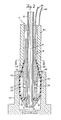
- a probe-gripper generally designated, 10, is shown in the drawings on a scale which is approximately 10 times larger than an actual probe- gripper made in accordance with the invention, it being understood that the probe-gripper is small enough to enter the open end of a conventional laboratory test tube.
- the probe-gripper includes a sample tube 12, extending lengthwise of the probe, and includes a central passageway 14, through which fluid may flow alternatively in opposite directions. Stainless steel has been found satisfactory for the tube.
- the sample tube includes a frustoconical nose 16, at one end, which may be either formed integral with the tube, or made separately and assembled on the tube, as for example, by the use of silver solder.
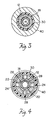
- the electrode is made of brass and includes an internal cylindrical plenum 20, which communicates with an external frustoconical plenum 22, by way of four passageways 24.
- the outer diameter of the tube 12 is cylindrical and the inner diameter of the electrode 18, is hexigonal. It may also assume any other polygonal shape.
- the inner diameter of the electrode 18, and the outer diameter of the tube 12, are insulated from each other by a nonconductive coating, as for example, teflon.
- the intermediate portion 42 of the elastomeric sheath surrounds the external plenum 22.
- the barrel 40 is made of stainless steel and is connected to ground by a conductor 44.
- the capacitance measuring means in the computer detects changes in capacitance below the electrode 18 and the barrel 40 incurring generally in the area designated area 46. For example, when the probe is at rest, in other words, not dipped in liquid or not engaging a piece of hardware, the capacitance of the area 46, would be determined by the dielectric value of the elastomeric member 30, and the surrounding air. This could be designated the zero point by the computer controlling the operation of the robot manipulated probe 10.
- the probe is shown inserted in the filter 50 with its elastomeric sheath engaging the interior wall 52 of the filter 50.
- the wall 52 is representative of a luer connector, or for that matter, the inner diameter of a test tube.
- pressurized air is caused to flow through the six passageways in the electrode 18 that surround the outer diameter of the tube 12, to the inner cylindrical plenum 20, through the radial passageways 24, to the exterior plenum 22, pressurizing it and causing the elastomeric sheath to bulge outwardly gripping the interior of the filter or other object it is intended to engage.
- the computer causes the robot to raise the gripper-probe 10 and to move it to any desired location.
- the filter if it is to be discarded, will drop from the gripper-probe when the plenum 22 is depressurized and the elastomeric sheath returns to its original position.
- probe-gripper is capable of many additional functions, as for example, to simultaneously energize a secondary gripping device through the sample tube 12 in order to transport test tubes or any other hardware.
Landscapes
- Engineering & Computer Science (AREA)
- Mechanical Engineering (AREA)
- Health & Medical Sciences (AREA)
- Clinical Laboratory Science (AREA)
- Chemical & Material Sciences (AREA)
- Chemical Kinetics & Catalysis (AREA)
- Automatic Analysis And Handling Materials Therefor (AREA)
- Manipulator (AREA)
- Investigating Or Analyzing Materials By The Use Of Electric Means (AREA)
Claims (6)
- Un dispositif de préhension à sonde (10) pour les systèmes de préparation d'échantillons comprenant:a. Un tube de prélèvement d'échantillon (12) se projetant dans le sens de la longueur par rapport à la sonde au travers duquel tube un fluide peut se déplacer tour à tour dans des directions opposées,b. une électrode annulaire (18) entourant le tube de prélèvement d'échantillon (12) contre l'une de ces extrémités.c. un tambour (40) entourant au moins une partie de l'électrode (18) ,d. des moyens (26, 44) permettant de brancher le tambour (40) et l'électrode (18) à des moyens de mesure de la réactance capacitive pour déceler toutes les variations de capacitance entre cesdits éléments,e. un élément annulaire en élastomère (30) entourant au moins une partie de l'électrode (18),f. des parties d'extrémités opposées (32, 38) dudit élément en élastomère (30) étant fixés à l'électrode (18),g. une partie annulaire intermédiaire (42) de l'élément en élastomère (30) libérée par l'électrode (18) pour créer une poche gonflable et,h. des moyens (28) d'acheminer le fluide sous pression dans le sens de la longueur de la sonde vers l'intérieur de la poche gonflable (42) pour la faire gonfler et se contracter en position d'adhérence ou de relâchement respectivement.
- un dispositif de préhension à sonde selon la revendication 1 dans lequel une partie d'extrémité (32) de l'élément annulaire en élastomère (30) est bloquée entre l'électrode (18) et le tambour (40), la partie d'extrémité opposée (38) de l'élément annulaire en élastomère (30) étant bloquée entre l'électrode (18) et une partie d'extrémité (16) du tube.
- Un dispositif de préhension à sonde (10) selon l'une ou l'autre des revendications 1 et 2 dans lequel au moins un orifice de passage de fluide (24) est placé entre le tube de prélèvement d'échantillon (12) et l'électrode et communique avec la chambre (20) entre l'électrode (18) et l'intérieur de la poche gonflable (42), laquelle poche se gonfle et se dégonfle lorsque le fluide sous pression est dirigé dans l'orifice d'écoulement du fluide
- Un dispositif de préhension à sonde (10) selon la revendication 1 dans lequel l'électrode (18) est en laiton et le tambour (40) est en acier.
- Un dispositif de préhension à sonde (10) selon la revendication 1 dans lequel le tube de prélèvement d'échantillon (12) est isolé de l'électrode (18).
- Un dispositif de préhension à sonde (10) selon la revendication 1 dans lequel l'intérieur de l'électrode (18) a une section polygonale et l'extérieur du tube de prélèvement d'échantillon (12) a une section de forme cylindrique, l'électrode (18) et le tube de prélèvement d'échantillon (12) créant entre eux des conduits d'écoulement du fluide (28) et formant de ce fait les moyens d'acheminer le fluide sous pression vers la poche gonflable (42).
Applications Claiming Priority (2)
| Application Number | Priority Date | Filing Date | Title |
|---|---|---|---|
| US22269 | 1987-03-05 | ||
| US07/022,269 US4747316A (en) | 1987-03-05 | 1987-03-05 | Probe-gripper |
Publications (3)
| Publication Number | Publication Date |
|---|---|
| EP0280965A2 EP0280965A2 (fr) | 1988-09-07 |
| EP0280965A3 EP0280965A3 (en) | 1989-02-22 |
| EP0280965B1 true EP0280965B1 (fr) | 1992-05-13 |
Family
ID=21808731
Family Applications (1)
| Application Number | Title | Priority Date | Filing Date |
|---|---|---|---|
| EP88102385A Expired EP0280965B1 (fr) | 1987-03-05 | 1988-02-18 | Dispositif de préhension d'échantillons pour système automatique de préparation d'échantillons |
Country Status (4)
| Country | Link |
|---|---|
| US (1) | US4747316A (fr) |
| EP (1) | EP0280965B1 (fr) |
| JP (1) | JP2653665B2 (fr) |
| DE (1) | DE3870927D1 (fr) |
Families Citing this family (12)
| Publication number | Priority date | Publication date | Assignee | Title |
|---|---|---|---|---|
| US5215376A (en) * | 1989-09-08 | 1993-06-01 | Becton, Dickinson And Company | Method for causing vortices in a test tube |
| DE4203638A1 (de) * | 1992-02-08 | 1993-08-12 | Boehringer Mannheim Gmbh | Fluessigkeitstransfereinrichtung fuer ein analysegeraet |
| GB9300200D0 (en) * | 1993-01-07 | 1993-03-03 | Unilever Plc | Article handling |
| US5372786A (en) * | 1993-07-02 | 1994-12-13 | Abbott Laboratories | Method of holding a sample container |
| JPH09127130A (ja) * | 1995-08-31 | 1997-05-16 | Teruaki Ito | 検体分取分注用ノズル装置 |
| EP0913671A1 (fr) * | 1997-10-29 | 1999-05-06 | Roche Diagnostics GmbH | Procédé et dispositif pour transférer des fluides dans un analyseur |
| DE19919305A1 (de) | 1999-04-28 | 2000-11-02 | Roche Diagnostics Gmbh | Verfahren und Vorrichtung zum Flüssigkeitstransfer mit einem Analysegerät |
| JP5883214B2 (ja) * | 2010-05-25 | 2016-03-09 | 株式会社東芝 | 自動分析装置 |
| EP3626343B1 (fr) * | 2018-09-18 | 2023-12-13 | Eppendorf SE | Dispositif de retenue destiné à retenir un récipient de pipetage d'un dispositif de pipetage |
| CN114377734A (zh) * | 2022-01-19 | 2022-04-22 | 重庆化工职业学院 | 一种化工实验用器皿柜 |
| DE102023125154A1 (de) * | 2023-09-18 | 2025-03-20 | Krones Aktiengesellschaft | Lochgreifer |
| CN119567225A (zh) * | 2024-12-13 | 2025-03-07 | 江苏麦孚精密技术有限公司 | 一种基于机械手的变频器生产用自动化取放装置 |
Family Cites Families (15)
| Publication number | Priority date | Publication date | Assignee | Title |
|---|---|---|---|---|
| US1195516A (en) * | 1916-08-22 | shields | ||
| US814169A (en) * | 1904-03-16 | 1906-03-06 | Filter & Brautechnische Maschinen Fabrik Act Ges | Apparatus for decanting liquids. |
| US2741381A (en) * | 1951-03-27 | 1956-04-10 | Colgate Palmolive Co | Transfer apparatus |
| US3103958A (en) * | 1961-03-23 | 1963-09-17 | Standard Oil Co | Liquid fill assembly |
| US3285299A (en) * | 1964-04-30 | 1966-11-15 | Nat Ind Products Company | Container sealing and filling means |
| DE1224539B (de) * | 1965-02-24 | 1966-09-08 | Rolf Huebner Dipl Ing | Vorrichtung zur Entnahme von Gasproben, insbesondere fuer Untertageraeume |
| US3352333A (en) * | 1965-03-31 | 1967-11-14 | Carrier Corp | Spray gun for cleaning tubes having radially expansible means for sealingly engagingsaid tube |
| FR2032002A5 (fr) * | 1969-02-14 | 1970-11-20 | Applic Gaz Sa | |
| CH522270A (de) * | 1970-09-30 | 1972-06-15 | Bbc Brown Boveri & Cie | Greifervorrichtung für Kernreaktorbelademaschine |
| US3741409A (en) * | 1971-12-01 | 1973-06-26 | Freeport Brick Co | Transfer apparatus for articles with a vertical passage |
| US3945486A (en) * | 1974-10-15 | 1976-03-23 | Glass Containers Corporation | Container supporting and transporting device |
| US4273505A (en) * | 1978-09-22 | 1981-06-16 | The United States Of America As Represented By The Administrator Of The National Aeronautics And Space Administration | Pneumatic inflatable end effector |
| DE2845094A1 (de) * | 1978-10-17 | 1980-05-08 | Freudenberg Carl Fa | Greifvorrichtung |
| US4326851A (en) * | 1980-10-24 | 1982-04-27 | Coulter Electronics, Inc. | Level sensor apparatus and method |
| FI70328C (fi) * | 1983-11-17 | 1986-09-15 | Tampella Oy Ab | Munstycke foer avskiljning av ett representativt prov fraon entoftbemaengd gas foer analysering daerav |
-
1987
- 1987-03-05 US US07/022,269 patent/US4747316A/en not_active Expired - Lifetime
-
1988
- 1988-02-18 EP EP88102385A patent/EP0280965B1/fr not_active Expired
- 1988-02-18 DE DE8888102385T patent/DE3870927D1/de not_active Expired - Lifetime
- 1988-03-04 JP JP63049932A patent/JP2653665B2/ja not_active Expired - Lifetime
Also Published As
| Publication number | Publication date |
|---|---|
| US4747316A (en) | 1988-05-31 |
| EP0280965A3 (en) | 1989-02-22 |
| DE3870927D1 (de) | 1992-06-17 |
| EP0280965A2 (fr) | 1988-09-07 |
| JP2653665B2 (ja) | 1997-09-17 |
| JPH01235853A (ja) | 1989-09-20 |
Similar Documents
| Publication | Publication Date | Title |
|---|---|---|
| EP0280965B1 (fr) | Dispositif de préhension d'échantillons pour système automatique de préparation d'échantillons | |
| EP1381495B1 (fr) | Mecanismes, dispositifs et procedes de prehension | |
| US10981162B2 (en) | Pipetting device having a pipette tip detection unit and method for detecting a pipette tip on a pipetting device | |
| US4841786A (en) | Specimen distributing system | |
| US6323035B1 (en) | Systems and methods for handling and manipulating multi-well plates | |
| US4799599A (en) | Specimen cup and cap assembly for clinical analyzer | |
| US5452619A (en) | Method for pipetting a blood sample | |
| US4829837A (en) | Robotic liquid separation sensing using a cannula | |
| US4325913A (en) | Reagent probe and method for fabrication thereof | |
| US3719087A (en) | Pipetting apparatus and method | |
| EP0607442B1 (fr) | Procede de dilution de liquide hautement visqueux | |
| EP0733404A1 (fr) | Embout de pipette | |
| AU2002255622A1 (en) | Gripping mechanisms, apparatus, and methods | |
| JPH0217448A (ja) | 空気式検出方式 | |
| EP0571100A1 (fr) | Dispositif de pipetage | |
| CA2034257A1 (fr) | Systeme automatise de distribution et de dilution | |
| US20050053454A1 (en) | Device and method for transferring objects | |
| JP4425512B2 (ja) | 可撓性ピペットストリップおよびその使用方法 | |
| US20040149015A1 (en) | System and method for verifying the integrity of the condition and operation of a pipetter device for manipulating fluid samples | |
| CN100549412C (zh) | 一种气体置换式带自动去吸头装置的微量进样泵 | |
| US4936152A (en) | Pipette tip storage tray and method of use | |
| US20250093376A1 (en) | Pipette tip positioning with guiding frame | |
| JPS60133302A (ja) | 2つの孔または2つの円筒体の中心距離を遠隔制御する装置 | |
| CN210081736U (zh) | 一种用于转移液体和搬运容器的机械手装置 | |
| EP3974841B1 (fr) | Dispositif de pipetage multicanaux |
Legal Events
| Date | Code | Title | Description |
|---|---|---|---|
| PUAI | Public reference made under article 153(3) epc to a published international application that has entered the european phase |
Free format text: ORIGINAL CODE: 0009012 |
|
| AK | Designated contracting states |
Kind code of ref document: A2 Designated state(s): DE FR GB IT NL SE |
|
| PUAL | Search report despatched |
Free format text: ORIGINAL CODE: 0009013 |
|
| AK | Designated contracting states |
Kind code of ref document: A3 Designated state(s): DE FR GB IT NL SE |
|
| 17P | Request for examination filed |
Effective date: 19890405 |
|
| 17Q | First examination report despatched |
Effective date: 19901206 |
|
| RBV | Designated contracting states (corrected) |
Designated state(s): DE FR GB |
|
| GRAA | (expected) grant |
Free format text: ORIGINAL CODE: 0009210 |
|
| AK | Designated contracting states |
Kind code of ref document: B1 Designated state(s): DE FR GB |
|
| REF | Corresponds to: |
Ref document number: 3870927 Country of ref document: DE Date of ref document: 19920617 |
|
| ET | Fr: translation filed | ||
| PLBE | No opposition filed within time limit |
Free format text: ORIGINAL CODE: 0009261 |
|
| STAA | Information on the status of an ep patent application or granted ep patent |
Free format text: STATUS: NO OPPOSITION FILED WITHIN TIME LIMIT |
|
| 26N | No opposition filed | ||
| REG | Reference to a national code |
Ref country code: GB Ref legal event code: 732E |
|
| REG | Reference to a national code |
Ref country code: FR Ref legal event code: TP |
|
| PGFP | Annual fee paid to national office [announced via postgrant information from national office to epo] |
Ref country code: FR Payment date: 20010131 Year of fee payment: 14 |
|
| PGFP | Annual fee paid to national office [announced via postgrant information from national office to epo] |
Ref country code: DE Payment date: 20010201 Year of fee payment: 14 |
|
| PGFP | Annual fee paid to national office [announced via postgrant information from national office to epo] |
Ref country code: GB Payment date: 20010202 Year of fee payment: 14 |
|
| REG | Reference to a national code |
Ref country code: GB Ref legal event code: IF02 |
|
| PG25 | Lapsed in a contracting state [announced via postgrant information from national office to epo] |
Ref country code: GB Free format text: LAPSE BECAUSE OF NON-PAYMENT OF DUE FEES Effective date: 20020218 |
|
| PG25 | Lapsed in a contracting state [announced via postgrant information from national office to epo] |
Ref country code: DE Free format text: LAPSE BECAUSE OF NON-PAYMENT OF DUE FEES Effective date: 20020903 |
|
| GBPC | Gb: european patent ceased through non-payment of renewal fee |
Effective date: 20020218 |
|
| PG25 | Lapsed in a contracting state [announced via postgrant information from national office to epo] |
Ref country code: FR Free format text: LAPSE BECAUSE OF NON-PAYMENT OF DUE FEES Effective date: 20021031 |
|
| REG | Reference to a national code |
Ref country code: FR Ref legal event code: ST |