EP0281094A2 - Compteur - Google Patents
Compteur Download PDFInfo
- Publication number
- EP0281094A2 EP0281094A2 EP88103151A EP88103151A EP0281094A2 EP 0281094 A2 EP0281094 A2 EP 0281094A2 EP 88103151 A EP88103151 A EP 88103151A EP 88103151 A EP88103151 A EP 88103151A EP 0281094 A2 EP0281094 A2 EP 0281094A2
- Authority
- EP
- European Patent Office
- Prior art keywords
- digit
- value
- radix
- signed
- digital position
- Prior art date
- Legal status (The legal status is an assumption and is not a legal conclusion. Google has not performed a legal analysis and makes no representation as to the accuracy of the status listed.)
- Granted
Links
Images



Classifications
-
- H—ELECTRICITY
- H03—ELECTRONIC CIRCUITRY
- H03K—PULSE TECHNIQUE
- H03K23/00—Pulse counters comprising counting chains; Frequency dividers comprising counting chains
- H03K23/004—Counters counting in a non-natural counting order, e.g. random counters
Definitions
- the present invention relates to a counter.
- a conventional high-speed binary counter includes a synchronous counter formed by D flip-flops, as shown in Fig. 4. The counting operation of this counter starts with presetting therein an initial value according to a count number, followed by count-up operation counter until it detects an overflow.
- Reference numeral 41 indicates binary counters and 42 initial value registers.
- CMOS complementary MOS
- a CMOS (complementary MOS) circuit is usually employed for forming a large scale integrated circuit of small power dissipation, but the maximum fan-in limit of the CMOS circuit is as small as 5 or so.
- the prior art system includes a circuit of a large fan-in, and hence inevitably adopts a multi-stage configuration therefore, leading to the defect that the operating speed of the conventional high-speed counter decreases with an increase in the count value.
- An embodiment of the present invention can provide a counter which permits a high-speed operation for a certain period of time, without dependence on the count value, through utilization of a radix-N, for example radix-2, Signed-Digit redundancy representation (which for radix-2 represents each digit of a binary number by one of three values -1, 0 and +1).
- a counter embodying the present invention includes a plurality of digit units of radix-2 Signed-Digit adders, each digit unit comprising an adder, a transfer digit generator and an interim value generator, and an initial value generator which is supplied with a desired count value to generate an initial value, prior to the counting operation.
- Each digit further includes an initial value register, an initial value and interim value selector, and an interim value register. The initial value from the initial value generator is applied to the initial value register. And a carry at a specified digit, which occurs after counting-up to a desired value, is detected, thereby the counter generates count end signal.
- the primary feature of the present invention is to form each digit of the counter by a radix-N, for example radix-2, Signed-Digit adder so as to implement a high-speed counting operation within a certain period of time, regardless of the count value.
- the radix-2 Signed-Digit adder is capable of performing a parallel addition without carry-propagation, permitting an addition in a certain period of time, regardless of an addend and an augend.
- the radix-2 Signed-Digit adder performs an addition without carry-propagation, by the following two steps of operation.
- the carry classification c is generated following the logic shown below in Table 1.
- the carry classification thus obtained is provided to higher adjacent digital position, i.e. the (i -1)th digital position.
- Table 2 shows a rule of addition according to which the transfer digit and the interim sum digit are derived from the addend and the augend in the i-th digital position, based on the carry classification c from the (i -1)th digital position.
- one of the two kinds of generation logic by which the transfer digit and the interim sum digit are set to 0 and -1 or -1 and +1, respectively, is chosen according to the carry classification c, thereby preventing the occurrence of the -1 carry propagation from the i-th digital position when the transfer digit from the (i - 1)th digital position and the interim sum digit in the i-th digital position are added together.
- one of the two kinds of generation logic by which the transfer digit and the interim sum digit are set to 0 and +1 or +1 and -1 is chosen according to the carry classification c from the (i - 1)th digital position, thereby preventing the occurrence of the +1 carry propagation from the i-th digital position when the transfer digit from the (i - 1)th digital position and the interim sum digit in the i-th digital position are added together.
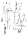
- Fig. 3 illustrates a specific operative example of the circuit arrangement of an adder of one digit of a radix-2 Signed-Digit adder, shown in Fig. 2, which performs an addition in accordance with the above-described rules of addition. More specifically, Fig. 3 shows an example of the adder in which each digit formed by any one of three values -1, 0 and +1 of the radix-2 Signed-Digit redundancy representation is represented by a binary code, as depicted below in Table 3, and the rules of addition shown in Tables 1 and 2 are employed.
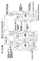
- Fig. 1A illustrates in block form a basic arrangement of a counter embodying the present invention and Fig. 1B an arrangement including an initial value generator.
- each digit unit 5 of the counter is formed by a radix-2 Signed-Digit adder 1, an initial value register 2 for presetting an initial value, an interim value register 3 for holding an interim value during the counting operation and an initial value and interim value selector 4 for switching between the initial value and the interim value.
- Reference numeral 10 indicates a count input, 11 a count output, 12 an addend input, 13 an Augend input, 14 an interim value input, 15 a transfer digit, and 16 a carry classification.
- an initial value Prior to the counting operation an initial value is preset.
- the initial value is precalculated from a count value so that an overflow can be detected at a specified digital position when the count has advanced by a desired value.
- each digit of the preset value represented by an ordinary 2's complement is replaced with a digit represented by the radix-2 Signed-Digit redundancy code (namely, the value 0 or 1 of each digit represented by the 2's complement is replaced with 0 or +1, respectively, in the radix-2 Signed redundancy representation).
- dots indicate that the value of the digit is equal to those of the higher adjacent and lower adjacent digits.
- dots indicates that the value of the digit is equal to those of the higher adjacent and lower adjacent digits.
- the values k and ⁇ k and the preset value are calculated from the desired count value A by the above-described method. Based on the values thus obtained, the counter shown in Fig. 1 is formed by digit units of (k + 1) digits so that n equals k.
- An interim value register 3 is synchronized with counting pulses from a count input 10 and is supplied with a new interim value which is the result of addition obtained by a radix-2 Signed-Digit adder 1, from an interim value input 14, and updates this interim value.
- An addend input 12 of the radix-2 Signed-Digit adder 1 for each digit is fixedly supplied with "+1" at the least significant digital position and "0s" at the other digital positions (corresponding to a value 1 as a whole). Accordingly, by adding the value 1 in the radix-2 Signed-Digit redundancy representation to the value of an augend input 13, which is also the output of an initial value and interim value selector 4, which is called an increment operation is realized, thereby performing a count-up operation of the counter.
- the most significant digital position of an interim value register 4 is used as a count output 11 and a control signal for the initial value and interim value selector 4.
- the most significant digital position is "+1"
- the initial value and interim value selector 4 selects the output value of the initial value register 2, and, at the same time, generates a count end pulse to the count output 11.
- the most significant digital position is "0”
- the initial value and interim value selector 4 selects the output value of the interim value register 3 and sends it to the addend input 12 of the radix-2 Signed-Digit adder 1 without generating count end pulse to the count output 11.
- the preset value ( ⁇ k - A) calculated from the desired count value A by the afore-said method is generated by an initial value generator 17 and the stored into the initial value register 2. Moreover, "+1" in the radix-2 Signed-Digit redundancy representation is stored into the interim value register 2, for each digit, prior to the counting operation.
- the counter Upon application of the count pulse arrived at the count input, the counter starts counting (time t ⁇ 0).
- the initial value and interim value selector 4 selects the output value of the initial value register 2, which is sent to the augend input 13 of the radix-2 Signed-Digit adder 1.
- To the addend input 12 are sent "+1" at the least significant digital position and "0s" at the other digital positions, and the result of addition is provided to an interim value input 14 of the interim value register 3.
- the initial value and interim value selector 4 selects the output value of the interim value register 3 and provides it to the augend input 13 of the radix-2 Signed Digit adder 1.
- the initial value to be preset can easily be precalculated by subtracting the count value from the value at which an overflow occurs.
- the counter of the present invention does not include a circuit of a large fan-in even if the count value is large. Also in the case where the counter is formed by a CMOS, which has generally a small fan-in limit but is widely used in a large scale integrated circuit because of its small power dissipation logic circuit, the counter can operate at high speed with a certain delay time of operation, regardless of an increase in the desired count value.
- CMOS complementary metal-oxide
- the counter can operate at high speed with a certain delay time of operation, regardless of an increase in the desired count value.
- a Signed-Digit adder For a radix-N Signed-Digit adder also, it is possible to calculate a value at which an overflow occurs at each digital position and to precalculate the initial value corresponding to the count value, through use of an iteration equation based on the rules of addition by using a Signed-Digit arithmetic technique. Accordingly, a Signed-Digit counter of high-speed operation can be realized by the radix-N Signed-Digit adder, the initial value register and the interim value register and the initial value and interim value selector.
- the counter of the present invention does not include a circuit of a large fan-in limit even if the desired count value increases, the counter, even if formed by the CMOS logic circuit or the like, can operate at high speed, with a certain delay time of operation, regardless of an increase in the desired count value.
- a counter which is capable of performing a high-speed operation with a certain delay time of operation, regardless of an increase in the count value, can be provided through utilization of the radix-2 Signed-Digit redundancy representation.
Landscapes
- Complex Calculations (AREA)
Applications Claiming Priority (2)
| Application Number | Priority Date | Filing Date | Title |
|---|---|---|---|
| JP49616/87 | 1987-03-04 | ||
| JP62049616A JPH07120267B2 (ja) | 1987-03-04 | 1987-03-04 | カウンタ回路 |
Publications (3)
| Publication Number | Publication Date |
|---|---|
| EP0281094A2 true EP0281094A2 (fr) | 1988-09-07 |
| EP0281094A3 EP0281094A3 (en) | 1990-05-09 |
| EP0281094B1 EP0281094B1 (fr) | 1994-06-01 |
Family
ID=12836165
Family Applications (1)
| Application Number | Title | Priority Date | Filing Date |
|---|---|---|---|
| EP88103151A Expired - Lifetime EP0281094B1 (fr) | 1987-03-04 | 1988-03-02 | Compteur |
Country Status (5)
| Country | Link |
|---|---|
| US (1) | US4837791A (fr) |
| EP (1) | EP0281094B1 (fr) |
| JP (1) | JPH07120267B2 (fr) |
| CA (1) | CA1291267C (fr) |
| DE (1) | DE3889746T2 (fr) |
Cited By (2)
| Publication number | Priority date | Publication date | Assignee | Title |
|---|---|---|---|---|
| RU2151463C1 (ru) * | 1997-09-23 | 2000-06-20 | Российский Федеральный Ядерный Центр - Всероссийский Научно-Исследовательский Институт Экспериментальной Физики | Устройство для счета импульсов |
| RU2179784C2 (ru) * | 2000-04-07 | 2002-02-20 | Пензенский технологический институт | Реверсивный счетчик импульсов с переменным модулем счета |
Families Citing this family (6)
| Publication number | Priority date | Publication date | Assignee | Title |
|---|---|---|---|---|
| JP2606326B2 (ja) * | 1988-10-25 | 1997-04-30 | 日本電気株式会社 | 乗算器 |
| JPH07120929B2 (ja) * | 1990-10-29 | 1995-12-20 | 三菱電機株式会社 | パルス発生回路 |
| KR100308205B1 (ko) * | 1998-09-29 | 2001-11-30 | 윤종용 | 저전력소모카운터 |
| US7397056B2 (en) * | 2005-07-06 | 2008-07-08 | Asml Netherlands B.V. | Lithographic apparatus, contaminant trap, and device manufacturing method |
| US7830729B2 (en) * | 2007-06-15 | 2010-11-09 | Micron Technology, Inc. | Digital filters with memory |
| US8667045B1 (en) * | 2011-05-11 | 2014-03-04 | Altera Corporation | Generalized parallel counter structures in logic devices |
Family Cites Families (9)
| Publication number | Priority date | Publication date | Assignee | Title |
|---|---|---|---|---|
| US3375358A (en) * | 1965-08-30 | 1968-03-26 | Fabri Tek Inc | Binary arithmetic network |
| US3462589A (en) * | 1965-12-22 | 1969-08-19 | Bell Telephone Labor Inc | Parallel digital arithmetic unit utilizing a signed-digit format |
| US3946219A (en) * | 1974-12-24 | 1976-03-23 | Veeder Industries, Inc. | Multiple purpose electronic counting system |
| JPS5674774A (en) * | 1979-11-22 | 1981-06-20 | Nec Corp | Arithmetic circuit with overflow detector |
| JPS5686535A (en) * | 1979-12-17 | 1981-07-14 | Fujitsu Ltd | Program counter circuit |
| US4751631A (en) * | 1983-02-04 | 1988-06-14 | Signal Processing Systems, Inc. | Apparatus for fast generation of signal sequences |
| US4700325A (en) * | 1984-02-08 | 1987-10-13 | Hewlett-Packard Company | Binary tree calculations on monolithic integrated circuits |
| JPS6126332U (ja) * | 1984-07-20 | 1986-02-17 | カルソニックカンセイ株式会社 | 積算計回路 |
| US4623982A (en) * | 1985-06-10 | 1986-11-18 | Hewlett-Packard Company | Conditional carry techniques for digital processors |
-
1987
- 1987-03-04 JP JP62049616A patent/JPH07120267B2/ja not_active Expired - Fee Related
-
1988
- 1988-02-29 US US07/162,096 patent/US4837791A/en not_active Expired - Fee Related
- 1988-03-02 DE DE3889746T patent/DE3889746T2/de not_active Expired - Fee Related
- 1988-03-02 EP EP88103151A patent/EP0281094B1/fr not_active Expired - Lifetime
- 1988-03-03 CA CA000560385A patent/CA1291267C/fr not_active Expired
Cited By (2)
| Publication number | Priority date | Publication date | Assignee | Title |
|---|---|---|---|---|
| RU2151463C1 (ru) * | 1997-09-23 | 2000-06-20 | Российский Федеральный Ядерный Центр - Всероссийский Научно-Исследовательский Институт Экспериментальной Физики | Устройство для счета импульсов |
| RU2179784C2 (ru) * | 2000-04-07 | 2002-02-20 | Пензенский технологический институт | Реверсивный счетчик импульсов с переменным модулем счета |
Also Published As
| Publication number | Publication date |
|---|---|
| JPS63216132A (ja) | 1988-09-08 |
| CA1291267C (fr) | 1991-10-22 |
| EP0281094A3 (en) | 1990-05-09 |
| DE3889746T2 (de) | 1994-09-08 |
| DE3889746D1 (de) | 1994-07-07 |
| EP0281094B1 (fr) | 1994-06-01 |
| US4837791A (en) | 1989-06-06 |
| JPH07120267B2 (ja) | 1995-12-20 |
Similar Documents
| Publication | Publication Date | Title |
|---|---|---|
| US4616330A (en) | Pipelined multiply-accumulate unit | |
| EP0955576A1 (fr) | Accumulateur numérique à haut débit à grande dynamique | |
| US3636334A (en) | Parallel adder with distributed control to add a plurality of binary numbers | |
| CA1332196C (fr) | Diviseur base 16 utilisant la selection de bits de quotient et des operations simultanees d'approximation et de correction | |
| EP0416869B1 (fr) | Additionneur/accumulateur numérique | |
| US4683548A (en) | Binary MOS ripple-carry parallel adder/subtracter and adder/subtracter stage suitable therefor | |
| US5181184A (en) | Apparatus for multiplying real-time 2's complement code in a digital signal processing system and a method for the same | |
| EP0281094B1 (fr) | Compteur | |
| US5177703A (en) | Division circuit using higher radices | |
| US6745219B1 (en) | Arithmetic unit using stochastic data processing | |
| RU2069009C1 (ru) | Суммирующее устройство | |
| US6127863A (en) | Efficient fractional divider | |
| US4503512A (en) | Cellular division circuit | |
| US4139894A (en) | Multi-digit arithmetic logic circuit for fast parallel execution | |
| US6434588B1 (en) | Binary counter with low power consumption | |
| EP0472030A2 (fr) | Procédé et appareil de modification d'un multiplieur à complément de deux afin d'y exécuter des multiplications de nombres non signés | |
| GB2226165A (en) | Parallel carry generation adder | |
| CN114895868B (zh) | 基于两位商计算的除法运算单元及除法器 | |
| US5920496A (en) | High speed correlator using up/down counter | |
| EP0214836A1 (fr) | Circuit d'addition à sélection de retenue | |
| EP0442220B1 (fr) | Décodeur | |
| RU2837596C1 (ru) | Многоканальный накапливающий сумматор по произвольным модулям | |
| SU894703A1 (ru) | Устройство дл умножени | |
| RU2183347C2 (ru) | Сумматор с переменным модулем сложения | |
| SU1171784A1 (ru) | Умножитель |
Legal Events
| Date | Code | Title | Description |
|---|---|---|---|
| PUAI | Public reference made under article 153(3) epc to a published international application that has entered the european phase |
Free format text: ORIGINAL CODE: 0009012 |
|
| AK | Designated contracting states |
Kind code of ref document: A2 Designated state(s): DE FR GB |
|
| PUAL | Search report despatched |
Free format text: ORIGINAL CODE: 0009013 |
|
| AK | Designated contracting states |
Kind code of ref document: A3 Designated state(s): DE FR GB |
|
| 17P | Request for examination filed |
Effective date: 19900823 |
|
| 17Q | First examination report despatched |
Effective date: 19920408 |
|
| GRAA | (expected) grant |
Free format text: ORIGINAL CODE: 0009210 |
|
| AK | Designated contracting states |
Kind code of ref document: B1 Designated state(s): DE FR GB |
|
| REF | Corresponds to: |
Ref document number: 3889746 Country of ref document: DE Date of ref document: 19940707 |
|
| ET | Fr: translation filed | ||
| PLBE | No opposition filed within time limit |
Free format text: ORIGINAL CODE: 0009261 |
|
| STAA | Information on the status of an ep patent application or granted ep patent |
Free format text: STATUS: NO OPPOSITION FILED WITHIN TIME LIMIT |
|
| 26N | No opposition filed | ||
| REG | Reference to a national code |
Ref country code: FR Ref legal event code: CA |
|
| PGFP | Annual fee paid to national office [announced via postgrant information from national office to epo] |
Ref country code: GB Payment date: 19980102 Year of fee payment: 11 |
|
| PGFP | Annual fee paid to national office [announced via postgrant information from national office to epo] |
Ref country code: FR Payment date: 19980311 Year of fee payment: 11 |
|
| PGFP | Annual fee paid to national office [announced via postgrant information from national office to epo] |
Ref country code: DE Payment date: 19980326 Year of fee payment: 11 |
|
| PG25 | Lapsed in a contracting state [announced via postgrant information from national office to epo] |
Ref country code: GB Free format text: LAPSE BECAUSE OF NON-PAYMENT OF DUE FEES Effective date: 19990302 |
|
| GBPC | Gb: european patent ceased through non-payment of renewal fee |
Effective date: 19990302 |
|
| PG25 | Lapsed in a contracting state [announced via postgrant information from national office to epo] |
Ref country code: FR Free format text: LAPSE BECAUSE OF NON-PAYMENT OF DUE FEES Effective date: 19991130 |
|
| REG | Reference to a national code |
Ref country code: FR Ref legal event code: ST |
|
| PG25 | Lapsed in a contracting state [announced via postgrant information from national office to epo] |
Ref country code: DE Free format text: LAPSE BECAUSE OF NON-PAYMENT OF DUE FEES Effective date: 20000101 |