EP0281849A2 - Système de commande d'embrayage pour une transmission à variation continue - Google Patents
Système de commande d'embrayage pour une transmission à variation continue Download PDFInfo
- Publication number
- EP0281849A2 EP0281849A2 EP88102737A EP88102737A EP0281849A2 EP 0281849 A2 EP0281849 A2 EP 0281849A2 EP 88102737 A EP88102737 A EP 88102737A EP 88102737 A EP88102737 A EP 88102737A EP 0281849 A2 EP0281849 A2 EP 0281849A2
- Authority
- EP
- European Patent Office
- Prior art keywords
- signal
- pressure
- clutch
- line
- control
- Prior art date
- Legal status (The legal status is an assumption and is not a legal conclusion. Google has not performed a legal analysis and makes no representation as to the accuracy of the status listed.)
- Granted
Links
Images




Classifications
-
- B—PERFORMING OPERATIONS; TRANSPORTING
- B60—VEHICLES IN GENERAL
- B60W—CONJOINT CONTROL OF VEHICLE SUB-UNITS OF DIFFERENT TYPE OR DIFFERENT FUNCTION; CONTROL SYSTEMS SPECIALLY ADAPTED FOR HYBRID VEHICLES; ROAD VEHICLE DRIVE CONTROL SYSTEMS FOR PURPOSES NOT RELATED TO THE CONTROL OF A PARTICULAR SUB-UNIT
- B60W30/00—Purposes of road vehicle drive control systems not related to the control of a particular sub-unit, e.g. of systems using conjoint control of vehicle sub-units
- B60W30/18—Propelling the vehicle
- B60W30/19—Improvement of gear change, e.g. by synchronisation or smoothing gear shift
-
- B—PERFORMING OPERATIONS; TRANSPORTING
- B60—VEHICLES IN GENERAL
- B60W—CONJOINT CONTROL OF VEHICLE SUB-UNITS OF DIFFERENT TYPE OR DIFFERENT FUNCTION; CONTROL SYSTEMS SPECIALLY ADAPTED FOR HYBRID VEHICLES; ROAD VEHICLE DRIVE CONTROL SYSTEMS FOR PURPOSES NOT RELATED TO THE CONTROL OF A PARTICULAR SUB-UNIT
- B60W10/00—Conjoint control of vehicle sub-units of different type or different function
- B60W10/02—Conjoint control of vehicle sub-units of different type or different function including control of driveline clutches
-
- B—PERFORMING OPERATIONS; TRANSPORTING
- B60—VEHICLES IN GENERAL
- B60W—CONJOINT CONTROL OF VEHICLE SUB-UNITS OF DIFFERENT TYPE OR DIFFERENT FUNCTION; CONTROL SYSTEMS SPECIALLY ADAPTED FOR HYBRID VEHICLES; ROAD VEHICLE DRIVE CONTROL SYSTEMS FOR PURPOSES NOT RELATED TO THE CONTROL OF A PARTICULAR SUB-UNIT
- B60W10/00—Conjoint control of vehicle sub-units of different type or different function
- B60W10/04—Conjoint control of vehicle sub-units of different type or different function including control of propulsion units
-
- B—PERFORMING OPERATIONS; TRANSPORTING
- B60—VEHICLES IN GENERAL
- B60W—CONJOINT CONTROL OF VEHICLE SUB-UNITS OF DIFFERENT TYPE OR DIFFERENT FUNCTION; CONTROL SYSTEMS SPECIALLY ADAPTED FOR HYBRID VEHICLES; ROAD VEHICLE DRIVE CONTROL SYSTEMS FOR PURPOSES NOT RELATED TO THE CONTROL OF A PARTICULAR SUB-UNIT
- B60W10/00—Conjoint control of vehicle sub-units of different type or different function
- B60W10/04—Conjoint control of vehicle sub-units of different type or different function including control of propulsion units
- B60W10/06—Conjoint control of vehicle sub-units of different type or different function including control of propulsion units including control of combustion engines
-
- B—PERFORMING OPERATIONS; TRANSPORTING
- B60—VEHICLES IN GENERAL
- B60W—CONJOINT CONTROL OF VEHICLE SUB-UNITS OF DIFFERENT TYPE OR DIFFERENT FUNCTION; CONTROL SYSTEMS SPECIALLY ADAPTED FOR HYBRID VEHICLES; ROAD VEHICLE DRIVE CONTROL SYSTEMS FOR PURPOSES NOT RELATED TO THE CONTROL OF A PARTICULAR SUB-UNIT
- B60W10/00—Conjoint control of vehicle sub-units of different type or different function
- B60W10/10—Conjoint control of vehicle sub-units of different type or different function including control of change-speed gearings
- B60W10/101—Infinitely variable gearings
-
- B—PERFORMING OPERATIONS; TRANSPORTING
- B60—VEHICLES IN GENERAL
- B60W—CONJOINT CONTROL OF VEHICLE SUB-UNITS OF DIFFERENT TYPE OR DIFFERENT FUNCTION; CONTROL SYSTEMS SPECIALLY ADAPTED FOR HYBRID VEHICLES; ROAD VEHICLE DRIVE CONTROL SYSTEMS FOR PURPOSES NOT RELATED TO THE CONTROL OF A PARTICULAR SUB-UNIT
- B60W10/00—Conjoint control of vehicle sub-units of different type or different function
- B60W10/10—Conjoint control of vehicle sub-units of different type or different function including control of change-speed gearings
- B60W10/101—Infinitely variable gearings
- B60W10/107—Infinitely variable gearings with endless flexible members
-
- B—PERFORMING OPERATIONS; TRANSPORTING
- B60—VEHICLES IN GENERAL
- B60W—CONJOINT CONTROL OF VEHICLE SUB-UNITS OF DIFFERENT TYPE OR DIFFERENT FUNCTION; CONTROL SYSTEMS SPECIALLY ADAPTED FOR HYBRID VEHICLES; ROAD VEHICLE DRIVE CONTROL SYSTEMS FOR PURPOSES NOT RELATED TO THE CONTROL OF A PARTICULAR SUB-UNIT
- B60W30/00—Purposes of road vehicle drive control systems not related to the control of a particular sub-unit, e.g. of systems using conjoint control of vehicle sub-units
- B60W30/18—Propelling the vehicle
- B60W30/1819—Propulsion control with control means using analogue circuits, relays or mechanical links
-
- F—MECHANICAL ENGINEERING; LIGHTING; HEATING; WEAPONS; BLASTING
- F16—ENGINEERING ELEMENTS AND UNITS; GENERAL MEASURES FOR PRODUCING AND MAINTAINING EFFECTIVE FUNCTIONING OF MACHINES OR INSTALLATIONS; THERMAL INSULATION IN GENERAL
- F16H—GEARING
- F16H61/00—Control functions within control units of change-speed- or reversing-gearings for conveying rotary motion ; Control of exclusively fluid gearing, friction gearing, gearings with endless flexible members or other particular types of gearing
- F16H61/66—Control functions within control units of change-speed- or reversing-gearings for conveying rotary motion ; Control of exclusively fluid gearing, friction gearing, gearings with endless flexible members or other particular types of gearing specially adapted for continuously variable gearings
- F16H61/662—Control functions within control units of change-speed- or reversing-gearings for conveying rotary motion ; Control of exclusively fluid gearing, friction gearing, gearings with endless flexible members or other particular types of gearing specially adapted for continuously variable gearings with endless flexible members
- F16H61/66254—Control functions within control units of change-speed- or reversing-gearings for conveying rotary motion ; Control of exclusively fluid gearing, friction gearing, gearings with endless flexible members or other particular types of gearing specially adapted for continuously variable gearings with endless flexible members controlling of shifting being influenced by a signal derived from the engine and the main coupling
-
- B—PERFORMING OPERATIONS; TRANSPORTING
- B60—VEHICLES IN GENERAL
- B60W—CONJOINT CONTROL OF VEHICLE SUB-UNITS OF DIFFERENT TYPE OR DIFFERENT FUNCTION; CONTROL SYSTEMS SPECIALLY ADAPTED FOR HYBRID VEHICLES; ROAD VEHICLE DRIVE CONTROL SYSTEMS FOR PURPOSES NOT RELATED TO THE CONTROL OF A PARTICULAR SUB-UNIT
- B60W50/00—Details of control systems for road vehicle drive control not related to the control of a particular sub-unit, e.g. process diagnostic or vehicle driver interfaces
- B60W2050/0001—Details of the control system
- B60W2050/0002—Automatic control, details of type of controller or control system architecture
- B60W2050/0008—Feedback, closed loop systems or details of feedback error signal
- B60W2050/0011—Proportional Integral Differential [PID] controller
-
- B—PERFORMING OPERATIONS; TRANSPORTING
- B60—VEHICLES IN GENERAL
- B60W—CONJOINT CONTROL OF VEHICLE SUB-UNITS OF DIFFERENT TYPE OR DIFFERENT FUNCTION; CONTROL SYSTEMS SPECIALLY ADAPTED FOR HYBRID VEHICLES; ROAD VEHICLE DRIVE CONTROL SYSTEMS FOR PURPOSES NOT RELATED TO THE CONTROL OF A PARTICULAR SUB-UNIT
- B60W50/00—Details of control systems for road vehicle drive control not related to the control of a particular sub-unit, e.g. process diagnostic or vehicle driver interfaces
- B60W2050/0001—Details of the control system
- B60W2050/0002—Automatic control, details of type of controller or control system architecture
- B60W2050/0012—Feedforward or open loop systems
-
- B—PERFORMING OPERATIONS; TRANSPORTING
- B60—VEHICLES IN GENERAL
- B60W—CONJOINT CONTROL OF VEHICLE SUB-UNITS OF DIFFERENT TYPE OR DIFFERENT FUNCTION; CONTROL SYSTEMS SPECIALLY ADAPTED FOR HYBRID VEHICLES; ROAD VEHICLE DRIVE CONTROL SYSTEMS FOR PURPOSES NOT RELATED TO THE CONTROL OF A PARTICULAR SUB-UNIT
- B60W50/00—Details of control systems for road vehicle drive control not related to the control of a particular sub-unit, e.g. process diagnostic or vehicle driver interfaces
- B60W2050/0001—Details of the control system
- B60W2050/0019—Control system elements or transfer functions
- B60W2050/0022—Gains, weighting coefficients or weighting functions
-
- B—PERFORMING OPERATIONS; TRANSPORTING
- B60—VEHICLES IN GENERAL
- B60W—CONJOINT CONTROL OF VEHICLE SUB-UNITS OF DIFFERENT TYPE OR DIFFERENT FUNCTION; CONTROL SYSTEMS SPECIALLY ADAPTED FOR HYBRID VEHICLES; ROAD VEHICLE DRIVE CONTROL SYSTEMS FOR PURPOSES NOT RELATED TO THE CONTROL OF A PARTICULAR SUB-UNIT
- B60W50/00—Details of control systems for road vehicle drive control not related to the control of a particular sub-unit, e.g. process diagnostic or vehicle driver interfaces
- B60W2050/0001—Details of the control system
- B60W2050/0043—Signal treatments, identification of variables or parameters, parameter estimation or state estimation
- B60W2050/0052—Filtering, filters
-
- B—PERFORMING OPERATIONS; TRANSPORTING
- B60—VEHICLES IN GENERAL
- B60W—CONJOINT CONTROL OF VEHICLE SUB-UNITS OF DIFFERENT TYPE OR DIFFERENT FUNCTION; CONTROL SYSTEMS SPECIALLY ADAPTED FOR HYBRID VEHICLES; ROAD VEHICLE DRIVE CONTROL SYSTEMS FOR PURPOSES NOT RELATED TO THE CONTROL OF A PARTICULAR SUB-UNIT
- B60W2510/00—Input parameters relating to a particular sub-units
- B60W2510/02—Clutches
- B60W2510/0241—Clutch slip, i.e. difference between input and output speeds
-
- B—PERFORMING OPERATIONS; TRANSPORTING
- B60—VEHICLES IN GENERAL
- B60W—CONJOINT CONTROL OF VEHICLE SUB-UNITS OF DIFFERENT TYPE OR DIFFERENT FUNCTION; CONTROL SYSTEMS SPECIALLY ADAPTED FOR HYBRID VEHICLES; ROAD VEHICLE DRIVE CONTROL SYSTEMS FOR PURPOSES NOT RELATED TO THE CONTROL OF A PARTICULAR SUB-UNIT
- B60W2710/00—Output or target parameters relating to a particular sub-units
- B60W2710/06—Combustion engines, Gas turbines
- B60W2710/0644—Engine speed
-
- B—PERFORMING OPERATIONS; TRANSPORTING
- B60—VEHICLES IN GENERAL
- B60W—CONJOINT CONTROL OF VEHICLE SUB-UNITS OF DIFFERENT TYPE OR DIFFERENT FUNCTION; CONTROL SYSTEMS SPECIALLY ADAPTED FOR HYBRID VEHICLES; ROAD VEHICLE DRIVE CONTROL SYSTEMS FOR PURPOSES NOT RELATED TO THE CONTROL OF A PARTICULAR SUB-UNIT
- B60W2710/00—Output or target parameters relating to a particular sub-units
- B60W2710/06—Combustion engines, Gas turbines
- B60W2710/0666—Engine torque
-
- F—MECHANICAL ENGINEERING; LIGHTING; HEATING; WEAPONS; BLASTING
- F16—ENGINEERING ELEMENTS AND UNITS; GENERAL MEASURES FOR PRODUCING AND MAINTAINING EFFECTIVE FUNCTIONING OF MACHINES OR INSTALLATIONS; THERMAL INSULATION IN GENERAL
- F16H—GEARING
- F16H59/00—Control inputs to control units of change-speed- or reversing-gearings for conveying rotary motion
- F16H59/14—Inputs being a function of torque or torque demand
- F16H59/18—Inputs being a function of torque or torque demand dependent on the position of the accelerator pedal
- F16H2059/183—Rate of change of accelerator position, i.e. pedal or throttle change gradient
-
- F—MECHANICAL ENGINEERING; LIGHTING; HEATING; WEAPONS; BLASTING
- F16—ENGINEERING ELEMENTS AND UNITS; GENERAL MEASURES FOR PRODUCING AND MAINTAINING EFFECTIVE FUNCTIONING OF MACHINES OR INSTALLATIONS; THERMAL INSULATION IN GENERAL
- F16H—GEARING
- F16H59/00—Control inputs to control units of change-speed- or reversing-gearings for conveying rotary motion
- F16H59/14—Inputs being a function of torque or torque demand
- F16H59/18—Inputs being a function of torque or torque demand dependent on the position of the accelerator pedal
Definitions
- the present invention generally relates to the torque or power transmission art. More specifically, the present invention relates to the operation and construction of continuously variable transmissions (CVT's).
- CVT's continuously variable transmissions
- the present invention particularly provides a clutch control system and technique for regulating the transfer of torque from an engine to a drive train through a CVT and a control clutch.
- the displaceable sheave includes a fluid constraining chamber for receiving fluid to move the sheave and thus change the effective pulley diameter; as fluid is exhausted from the chamber, the pulley diameter changes in the opposite sense.
- the effective diameter of one pulley is adjusted in one direction as the effective diameter of the second pulley is varied in the opposite direction, thereby effecting a change in the drive ratio between the input shaft coupled to an input pulley and an output shaft coupled to an output pulley.
- the ratio changes continuously as the pulley diameters vary.
- Such transmissions frequently are referred to in the art as a continuously variable transmission, or CVT.
- This control system is designed to handle those situations where the total vehicle torque, interia torque plus road load, will load the engine down. These situations occur when the vehicle is stationary or at a slow speed. For the other situations, when the vehicle torque would accelerate the engine rather than load it down, this normal start mode would yield an undesirable response. These other situations are controlled as set forth in a co-pending application entitled “Special Start Technique For Continuously Variable Transmission Clutch Control", Serial No. 25,476, filed on March 13, 1987.
- the principal object of the present invention lies in providing a continuously variable transmission clutch control system which generally overcomes the deficiencies of the prior art.
- a further object may be found in improving the response of a continuously variable transmission driven vehicle to changes in driver demand while the clutch is being controlled.
- the present invention provides an improved clutch control system for use with a continuously variable transmission driven vehicle.
- the improved controller controls engine speed as a function of driver demand (throttle) by applying a controlled clutch pressure throughout engagement to lock-up.
- Throttle signals provide engine torque and engine speed set points based on characteristics of the engine in use. Filters having preselected initial conditions modify the set points to approximate actual vehicle response characteristics and enhance driveability.
- the engine torque signal as derived from the engine map, provides a feed forward signal indicative of a desired clutch pressure for a particular driver demand. This signal combines with an engine speed error signal developed from the modified desired engine speed set point signal and the actual engine speed feedback signal.
- the system passes this signal for clutch pressure control only if it represents a pressure signal greater than the touch-off value for clutch operation. This is done to prevent the clutch from backing off of the touch off point.
- a pressure control loop maintains the clutch pressure at a level as indicated by the engine speed loop and the engine map derived torque feed forward and provides a signal with the appropriate duty cycle to an electro hydraulic plan clutch control valve.
- the engine speed loop provides an enhanced response through the incorporation of the CVT belt ratio information into the speed control loop gain. All ratio conditions thereby provide improved response to change in driver demand and ratio.
- the present invention further provides a pressure control signal additionally responsive to the variations in the overall line pressure.
- a signal representative of the line pressure and provides the desired gain for the pressure loop control and thus maintains the desired response of the pressure loop as the line pressure varies.
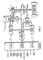
- a throttle signal 10 controls the operation of an engine 12 which transmits torque via shaft 14 to a primary pulley 16 in a CVT 18.
- a flywheel and damping arrangement may be included on shaft 14 between the engine 12 and the primary pulley 16.
- a metal or elastomeric belt 20 connects the primary pulley 16 to a secondary pulley 22 to transmit torque to a second shaft 24.
- a pump 26 may also be driven by the first shaft 14 to provide line pressure for the hydraulic system and the controls of the CVT 18.
- the second shaft 24 drives the input to a clutch 28 which in turn provides a torque to a third shaft 30.
- the third shaft 30 drives a reduction differential gear arrangement 32 as drive line to provide power to the vehicle wheels 34.
- an electronic controller 36 receives throttle, engine speed, clutch input speed, clutch output speed, clutch pressure, temperature, driver demand, idle, shift lever and other information input signals as shown at the left of FIG. 1.
- the electronic controller 36 operates in a logical fashion discussed in greater detail below to provide a ratio control signal on a line 38, a line pressure control signal on a line 40 and a clutch control signal on a line 42.
- the signal on the line 38 to a ratio control valve 44 controls the hydraulic pressure on a line 46 to the primary pulley 16 of the CVT 18 to control the ratio between the primary pulley 16 and the secondary pulley 22, i.e. , the belt ratio (RATC).
- the signal on the line 40 communicates with a line pressure regulator 48.
- the line pressure regulator 48 provides line pressure from fluid flow of pump 26 via conduit 50 to the ratio control valve 44, a clutch control valve 52.
- the output of the line pressure regulator on the line 50 also controls the pressure at the secondary pulley 22 to ensure that the belt 20 does not slip.
- the output signal on the line 42 to the clutch control valve 52 controls the output of the clutch control valve 52 on a line 54 to the manual and servo valves 56 which controls the fluid flow on the line 58 to the clutch 28. This is the signal which provides the pressure at the clutch 28 and hence regulates the torque transfer from the second shaft 24 to the third shaft 30.
- Ratio control valve 44 may be controlled in the preferred embodiment as set forth in a co-pending application entitled “Ratio Control Technique For A Continuously Variable Transmission System," Serial No. 25,389, filed on March 13, 1987.
- a shift lever signal on a line 60 provides an additional control of the manual and servo valves 56.
- the shift lever signal on the line 60 indicates that the vehicle is in a neutral or park mode
- the manual control within the valve arrangement 56 is closed. This prevents fluid from flowing to the clutch 28 and thus prevents any torque transfer through the clutch 28 when the vehicle is in the neutral mode.
- the ratio of NE to NCI will correspond to and provide a measure of the transmission belt ratio, RB.
- the difference between NCI and NCO provides a measure of the slippage at the clutch 28.
- NCI equals NCO, the clutch 28 is locked-up with no slippage.
- the system of FIG. 1 operates in a number of driving or vehicle operation modes.
- the main logic section determines which of these modes the system is operating in and accordingly provides appropriate information for clutch control.
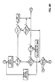
- the overall logic flow for the clutch control is set forth in more detail in the flow charts of FIGS. 9A and 9B. The following represents a brief description of the modes of operation, and the general characteristics of the clutch during those modes: OFF MODE:
- the clutch is destroked, i.e. , the clutch plates are disengaged.
- a full-on duty cycle is sent to the clutch control valve, but flow to the clutch is blocked by the manual valve. This corresponds to the engine running while the vehicle is in PARK or NEUTRAL.
- ENGAGE MODE The system engages the clutch without transmitting any torque through the clutch.
- the pressure loop begins to control the clutch pressure to bring it up to the touch-off pressure set point. This corresponds to a transition between the OFF mode and a HOLD mode.
- HOLD MODE The clutch is at the touch-off point; the pressure loop maintains clutch pressure at the touch-off pressure. At this pressure, the plates are engaged and allow a small amount of vehicle creep which is adjustable by changing the value of PCE. This corresponds to the vehicle being at idle.
- PRESSURE MODE The clutch pressure set point is derived from sources other than the speed loop and related structures described herein ( e.g. , the special START mode application described in co-pending application Serial No.
- SPEED MODE The SPEED loop and a feed-forward function determine the set point for the pressure controller.
- the clutch is slipping and controlling engine speed. This corresponds to a normal start for a vehicle transition from idle up to driving speed.
- LOCK-UP MODE The clutch is locked up and not slipping. A full-on duty cycle is sent to the control valve to maintain the pressure at the clutch to prevent slipping. This corresponds to a normal drive mode for a vehicle.
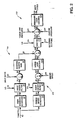
- FIG. 2 therein is shown a block diagram representation of the operation of the control system according to the present invention.
- Those skilled in the art will appreciate that this represents a block diagram system representation to be embodied through the programming of the electronic controller 36 illustrated in FIG. 1. Specific programming and instructions will depend upon the particular controller selected for use in the system and other variables not critical to the operation of the present invention.
- the explanation embodied in FIG. 2 and the flow charts discussed below provide the envisioned logical steps. It is deemed that one skilled in the art would be able to readily generate the program for the particular electronic controller to be used in any particular system.
- a throttle signal on a line 62 represents driver demand for a particular engine function.
- the throttle signal may be in absolute terms or may represent the angular orientation of a throttle valve in a typical carburetor system.
- the throttle signal on the line 62 is provided to a feed forward open loop 64 at a feed forward schedule 66.
- the throttle signal on the line 62 also communicates with a closed loop engine speed control loop 68 and an engine speed schedule 70.
- the feed forward schedule 66 and the engine speed schedule 70 provide a torque feed forward set point on a line 72 and an engine speed set point on a line 74 according to the respective schedules derived for the particular engine in the vehicle as explained below in conjunction with FIGS. 3A-3C.
- the feed forward schedule 66 provides a torque set point on a line 72 to a first order filter 74.
- the first order filter 74 in conjunction with initial conditions received on a line 76, transforms the set point signal received on a line 72 to a filtered, modified torque signal on a line 78.
- the transfer function of the first order filter 74 may be given by the following equation: where: TRQENF is the signal on the line 78 and TRQEN represents the signal on the line 72.
- the filter components may be selected to provide specific filter characteristics as defined by the following equations (2) and (3):
- TRQENF(n) XFFC(n) (2)
- XFFC(n + 1) - BFFC [TRQEN(n) - XFFC(n)] + TRQEN(n) (3)
- BFFC exp (- ⁇ ff ⁇ Tss)
- Tss sample period of speed loop
- ⁇ ff cut off frequency of filter
- n cumulative number of sample periods
- TRQEN output of feed forward schedule (Line 72)
- TRQENF Output of feed forward filter (Line 78)
- the operation of the filter further depends upon the initial condition signal received on the line 76.
- the initial condition is chosen as zero as will be explained further below.
- the filtered set point signal on the line 78 is passed to a multiplier 80 where it is multiplied by the belt ratio signal received on a line 82 to provide a clutch torque signal on a line 84 as given by the following equation (4):
- TRQCN RATC ⁇ TRQENF (4)
- TRQCN represents the signal on the line 84 and, as mentioned, TRQENF represents the signal on the line 78.
- the throttle signal from the line 62 proves an engine speed set point signal on the line 74 as a function of the engine speed schedule 70.
- a first order filter 92 in response to the engine speed set point on the line 74 and an initial condition on a line 94, provides a filtered set point signal on a line 96.
- the general transfer function for the filter 92 is given by the following equation (6): where NESPCF is the output signal on a line 96 and NESPC represents the input signal on the line 74.
- the initial condition is chosen to be a filtered value of the actual engine speed read into the controller just before entrance into normal start mode as discussed more fully below.
- the output signal on line 96 provides one input to a summing junction 98.
- the other input to the summing junction 98 represents the actual engine speed from a line 100.
- This provides a first error signal on line 102.
- the signal on line 102 passes a speed loop control operation to block 104 to provide an error signal on line 106 as the second input to the summing junction 90.
- the speed loop control 104 will be discussed in more detail below in conjunction with FIG. 4.
- the output of the summer 90 on a line 108 represents a pressure set point which is provided to a pressure control loop 110 at a switch network 112.
- the switch network 112 on an equivalent functional block may select between an external set point signal on a line 114, such as is generated for special start conditions as explained in co-pending application Special Start Technique For A Continuously Variable Transmission Control System, referenced above.
- the switch network 112 also operates to limit the transmission of the signal from the line 108 for pressure control solely when that signal is greater than or equal to zero as described more fully below.
- the signal on line 108 would cause the clutch pressure to drop below the touch off pressure, the signal is blocked in response to the comparison from line 116 so that the clutch pressure remains at the minimum touch off pressure during operation.
- the touch off pressure is the necessary pressure to bring the clutch plates into contact.
- Switch function network 112 also serves to add no additional pressure setpoint to the pressure loop control (128), to maintain touch off pressure as in engage and hold modes.
- the output signal on the line 118 from the switch 112 provides one input to a summing junction 120.
- the second input to the summing junction 120 comes from a touch off pressure signal which is that signal necessary to generate the pressure to cause the clutch plates to make initial contact.
- the final input to the summing junction 120 comes from a transducer which provides a clutch pressure signal as a measure of actual clutch pressure on a line 124.
- the summing junction 120 generates an error signal on a line 126 which through the pressure loop control 128 provides an output signal on a line 130 to generate a signal having the appropriate duty cycle to operate the clutch valve so as to generate the desired clutch pressure which is then fed back via the closed loop by the line 124.
- the operation of the pressure loop control 128 is explained below in more detail in conjunction with FIG. 5.
- FIG. 3A therein is shown a characteristic engine map which plots engine torque in foot-pounds against engine speed in RPMs ( ⁇ 1,000) as a function of the engine throttle setting, which in the preferred embodiment is measured in degrees of the throttle valve.
- this mapping illustrated in FIG. 3A varies with particular engines.
- a start mode strategy may be mapped on the engine map of FIG. 3A as illustrated by the line 132 which would represent the selected start mode for bringing the clutch pressure from touch off pressure during the HOLD mode to a clutch pressure which controls the engine speed during START mode, to a lockup in the DRIVE mode for a vehicle.
- a schedule of engine torque may be plotted against driver demand measured by throttle as illustrated by the graph of FIG. 3B. This graph is generated from that of FIG. 3A by picking off the corresponding engine torque valves for successive throttle settings. This schedule may then be used to generate the signal on the line 72 of FIG. 2 as a function of the throttle setting received on the input line 62 of FIG. 2.
- a corresponding graph of desired engine speed set point may be generated as a function of throttle as illustrated in FIG. 3C. Again, this graph represents a pick off of corresponding engine speed points for particular throttle settings corresponding to the graph line 132 of FIG. 3A.
- This schedule then provides an engine speed set point schedule to provide an engine speed set point on a line 74 as a result of the input throttle signal on the input line 62.
- engine speed schedule and the feed forward (torque) schedule are interrelated and one may be generated from the other with reference to the original engine map illustrated in FIG. 3A.
- the first order filter 74 is included in the open loop torque control 64 to provide for a realistic feel and response to the driver.
- a net positive step signal would be provided to the summing junction 90 which would provide an immediate jump in the pressure to the clutch and hence cause the vehicle to jolt or lurch in the drive direction. This can stall the engine and is generally unsatisfactory.
- Setting the initial condition on the line 76 to the filter 74 provides a zero starting point so that the initial signal on line 98 to the summing junction 90 will always be zero.
- the first order filter 74 provides an exponential increase in the output signal in response to a dramatic increase, such as a step demand, in the signal on the input line 72.
- the time constant of the filter 74 may be then empirically chosen to provide the desired realistic response rather than the jolt which would otherwise occur.
- the first order filter 92 in the closed engine speed control loop 68 provides for the slowing of the response to rapid changes in driver demand.
- a rapid rise in throttle corresponding to the driver stepping into the throttle rapidly would normally provide a quick jump in the engine speed set point on the line 74 which would provide a significant error signal at the output of the sum junction 98 and a corresponding decrease in the signal on line 106 to the second summing junction 90 which would generate a lull or a quick sag in the pressure set point signal and a lessening of the pressure at the clutch.
- the inclusion of the first order filter 92 slows the response to the driver demand as a function of the characteristics chosen for that filter as explained above. These values may be chosen empirically to provide for the desired feel depending on the particular engine and vehicle being utilized.
- the initial condition received by the filter 92 on the line 94 is chosen to provide a zero error signal at the beginning of start mode. This is done by choosing the initial condition on the line 94 to be a filtered actual engine speed measure. Hence, there would be no difference signal at the output of the summing junction 98. Then, as time elapses, the signal on the line 106 would gradually come to the appropriate value. In this fashion, the hesitation associated with a rapid increase in throttle demand may be avoided.
- the same conditions which lead to a lull or slip in the clutch upon a rapid driver demand would cause a surge upon a rapid decrease in driver demand. That is, when the driver lets up on the throttle quickly, the engine speed set point would drop below the actual engine speed to provide a net positive signal to the summing junction 90 and hence an increase in the pressure set point signal on the line 108 with the result in a rapid increase in the pressure at the clutch and a surge felt by the driver.
- the first order filter 92 softens this response as a function of its time constant which may be empirically determined to provide the desired feel for the driver as a match between the engine and the vehicle.
- the filtered speed signal as an initial condition on the line 94 again guarantees that a net zero signal will occur at the time of each entrance into start mode.
- FIG. 4 therein is shown a block logic representation for the speed loop control 104 of FIG. 2.
- the engine speed set point on a line 96 is combined with actual engine speed from a line 100 at a summation junction 98 to provide a first error signal on a line 102.
- a speed loop control circuit or operation 104 modifies the signal on line 102 to provide a second error signal on a line 106 which is combined at the summing junction 90 with the feed forward torque generated signal on line 88.
- This provides a normal start pressure signal on a line 108 which is monitored by a limiter function 134 to ensure that at least touch off pressure is maintained at the clutch.
- the speed loop control circuit 104 is shown in greater detail in FIG. 4.
- a belt ratio signal on a line 136 is multiplied by a nominal gain at block 138 to provide a modified gain signal on a line 140 to provide the multiplier at an operation block 142.
- This provides a gain in the engine speed control loop 68. As seen, this is a function of the belt ratio and hence provides a constant response of the control for all belt ratios.
- KASC RATC ⁇ KASCN (9)
- E1SC NESPCF - NE (10)
- E2SC KASC ⁇ E1SC (11)
- KASCN nominal speed loop gain (gain at block 138)
- RATC belt ratio (signal on line 136)
- KASC speed loop proportional gain (signal on line 140)
- E1SC speed loop error (signal on line 102)
- E2SC speed loop pressure set point (signal on line 104)
- NE actual engine speed (signal on line 100)
- the signal on the line 106 is combined with the Feed forward signal on line 88 to provide an output signal on the line 108 representing the normal start mode pressure setpoint.
- PCC(n) normal start mode pressure setpoint.
- the limiter block 134 previously shown as being a function of switch 112, generally illustrates the two state nature of the signal PCC (the setpoint at line 108). This ensures that the signal on the line 118 to the summing junction 120 will never have a negative value to cause the output signal from the pressure loop control on the line 130 to drop below the tough off pressure and cause the plates of the clutch to pull apart during start mode operation.
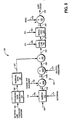
- FIG. 5 therein is shown a pressure loop control in block diagram form.
- the pressure loop control function 128 receives a pressure error signal at line 126 as a function of the feedback clutch pressure on line 124 and the incoming normal start mode set pressure signal at line 108 and the touch off pressure setpoint on line 122.
- the summation function 120 is shown as a first summation block 120A and a second summation block 120B. In all other respects, that portion of the block diagram of FIG. 5 is equivalent to that of FIG. 2.
- the pressure loop control function 128 is shown in greater detail in FIG. 5.
- the filtered line pressure setpoint at line 144 determines a pressure loop gain adjustment factor at a line 146 as a function of the pressure gain schedule 148 as shown in FIG. 6.
- the line pressure control is operated in an open loop scheduled mode since the CVT design does not have the benefit of a pressure transducer to measure the actual line pressure. This is shown in detail in co-pending application (ES08606) entitled "Control System For Controlling The Line Pressure In A Continuously Variable Transmission", Serial No. 936,527. Therefore, the line pressure setpoint is filtered to approximate the actual line pressure and it is this signal that is used to adjust the clutch pressure loop gain.
- the pressure loop gain adjustment factor at line 146 operates on a nominal gain at block 150 to provide the multiplying factor for the gain of the pressure loop at a multiplier block 152.
- the product of the multiplying gain from the line 151 times the error signal on the line 126 at the multiplier block 152 results in a pressure error signal on a line 154.
- PCC normal start mode set pressure (line 118)
- PCE clutch touch-off pressure (line 122)
- PCLUSP clutch pressure set point (line 118a)
- PCL actual clutch pressure (line 124)
- E1PC pressure error (line 126)
- a lead lag compensation may be performed upon the pressure error signal at line 154.
- This is represented generally by a block 156 responsive to the signal at line 154 and an initial condition imposed at line 158.
- the operation of the lead lag function at block 156 may be given by the following formula (17): where E3PC is the signal at line 160.
- This function serves to provide a dynamic modification or compensation which gives a better bandwidth, faster response, and retains system stability for the pressure loop control.
- the lead "zero" value in the numerator of equation 17 may be chosen to provide compensation for the lag induced by the control valve dynamics.
- the lag "pole" in the denominator of equation 17 may be given a sufficiently large value so as not to figure in the practical result.
- E3PC(n) CPDC [E2PC(n) - X1PDC(n)] + X1PDC(n) (18)
- X1PDC(n+1) -BPDC [E2PC(n) - X1PDC(n)] + E2PDC(n) (19)
- E3PC output of lead/lag (line 160)
- Tsp sample period of pressure loop
- CPDC ⁇ plag/ ⁇ plead
- BPDC exp (- ⁇ plag*Tsp) X1PDC lead/lag state variable
- an integral-lead function is inserted at a block 162.
- the integral-lead function 162 provides a control signal at line 166. It will be appreciated by those skilled in the art that any signal at the line 160 other than zero will provide a ramp output at line 166 proportional to that signal which through operation of the feedback control would tend to provide a correction error signal to bring the system back toward a zero, steady state error signal.
- the lead function in the integral is introduced to compensate for the lag of the hydraulics.
- the integral lead operation of block 162 may be given by the following equation (20): where E4PC is a signal at line 156.
- E4PC(n) X2PIC(n) + E3PC(n) (21)
- X2PIC(n+1) X2PIC(n) + DPIC ⁇ E3PC(n) (22)
- X2PIC state variable of integrator/lead
- X2LPIC lower limit of integrator
- X2UPIC upper limit of integrator
- the signal at line 166 may then be combined at a summation junction 168 with a null signal from a line 170.
- the null signal at line 170 represents a steady state error which corresponds to the clutch control valve in use. This serves to further ensure that the steady state zero value will be achieved to provide the desired duty cycle signal as an output at the line 130.
- FIG. 6 therein is shown a typical pressure loop gain schedule which illustrates the pressure loop gain adjustment factor on a vertical scale as a function of the filtered line pressure setpoint in pounds-per-square-inch (psi).
- the incorporation of this schedule into the pressure loop control at block 148 of FIG. 5 further facilitates the accurate response of the clutch pressure control loop by incorporating a value dependent upon the filtered line pressure setpoint. This maintains a constant open loop gain for all values of the given line pressure.
- the schedule of FIG. 6 represents an empirical tabulation which may be performed for particular systems in which the control of the present invention may be utilized.
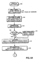
- a speed loop setpoint is determined at block 204 as a function of throttle from the engine speed schedule.
- a feed forward torque is determined at a block 206 which is a second function of the throttle. This represents the interrelation between the throttle, engine speed and engine torque.
- the system determines whether the speed initial flag has been set. If YES, then initial condition is set for the first order filter 92 at the filtered engine speed and for the filter 74 at zero as shown by block 210. The system then branches back at line 212.
- the system advances to line 212 without setting the initial conditions.
- the system then performs the filtered 92 functions at block 214 and proceeds to the filter 74 functions at block 216.
- the system generates the feed forward torque signal adjusted by the belt ratio.
- Block 222 represents a calculation of the feed forward pressure as a function of the product of the inverse clutch gain times the clutch torque signal.
- a block 224 represents the speed error calculation, which is then modified at block by the proportional gain generator from the speed loop 226 control 104.
- a normal start mode clutch pressure setpoint may then be determined at a block 228 as a function of the difference between the feed forward pressure and the speed error signal from the block 222 and the proportional gain block 226, respectively.
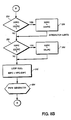
- a decision block 230 represents the determination of whether the normal start mode clutch pressure set point is less than zero. If it is, then a block 232 represents a setpoint limiter which comes into play to guarantee that the clutch does not fall below the threshold touch-off value during normal start mode. If the pressure setpoint signal is greater than zero, then the system advances at line 234 to the pressure loop control.
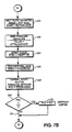
- FIGS. 8A and 8B therein is shown the flow chart for the pressure loop control 110 of FIG. 2.
- the system proceeds to provide an error signal at a block 238 which is a function of the feedback actual clutch pressure, the pressure setpoint signal and the touch-off pressure setpoint.
- a block 240 represents the calculation of the pressure loop gain as a function of the filtered line pressure setpoint which may be obtained from a look-up table such as that illustrated in FIG. 6. This value at a block 242 provides a proportional gain to the error signal from the block 238.
- the system determines whether the pressure initial condition flag has been set.
- a lead/lag function as explained above, is performed at a block 250 followed by an integrator lead function at a block 252.
- the lead/lag block 250 compensates in a dynamic sense for the lag introduced by the control valve and provides for improved response in the pressure control loop.
- the integrator lead block 252 serves to ensure that the steady state error value is zero. It's associated lead term compensates for the lag induced in the system by the hydraulics.
- the integrator lead function 162 in operation the integrator lead function 162 must be limited so that the saturation of its digital implementation will not saturate the input to the pulse width modulation generator from the duty cycle signal at the line 130.
- the output of the integrator must be compared with the upper and lower limits for the integrator.
- a decision block 254 compares the output of the integrator with its upper limit. If it is greater than its upper limit, then the value is set at the upper limit at a block 256 and the system branches back.
- the output of the integrator is compared with its lower value. If it is less than its lower value, then the output is set at that lower value at a block 260 and the system branches back.
- the system performs the loop null function to compensate for the valve in the system and then branches to the pulse width modulation generator at 264 for generation of the appropriate duty cycle signal to control the clutch pressure valve.
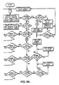
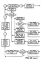
- FIGS. 9A and 9B therein is shown the general logic flow chart for the operation of the entire CVT clutch control system which is similar to that described in the previous application in U. S. Patent No. 4,648,496, entitled “Clutch Control System for Continuously Variable Transmission”.
- FIG. 9B represents an alternative embodiment for the portion of the flow chart of FIG. 9A bounded by I, II, III and IV.
- FIGS. 7A, 7B, 8A and 8B represent the steps illustrated at the left of FIG. 9A and indicated by the identification i, ii, iii and iv.
- the corresponding indications have been placed on the flow charts of FIGS. 7A, 7B, 8A and 8B.
- a further description of the operation of the main logic at this time is deemed unnecessary in view of the incorporation of the description from the previous application.
- Temperature compensation may be provided in the preferred embodiment by reference to a co-pending application entitled “Temperature Compensation Technique For A Continuously Variable Transmission System,” Serial No. 25,392, filed on March 13, 1987.
- pulse width modulation in the preferred embodiment may be accomplished as taught in a co-pending application entitled “Pulse Width Modulation Technique,” Serial No. 25,477, filed on March 13, 1987.
Landscapes
- Engineering & Computer Science (AREA)
- Chemical & Material Sciences (AREA)
- Combustion & Propulsion (AREA)
- Mechanical Engineering (AREA)
- Transportation (AREA)
- Automation & Control Theory (AREA)
- General Engineering & Computer Science (AREA)
- Hydraulic Clutches, Magnetic Clutches, Fluid Clutches, And Fluid Joints (AREA)
- Control Of Driving Devices And Active Controlling Of Vehicle (AREA)
- Control Of Transmission Device (AREA)
Applications Claiming Priority (2)
| Application Number | Priority Date | Filing Date | Title |
|---|---|---|---|
| US25391 | 1987-03-13 | ||
| US07/025,391 US4793454A (en) | 1987-03-13 | 1987-03-13 | Continuously variable transmission clutch control system |
Publications (3)
| Publication Number | Publication Date |
|---|---|
| EP0281849A2 true EP0281849A2 (fr) | 1988-09-14 |
| EP0281849A3 EP0281849A3 (en) | 1989-01-18 |
| EP0281849B1 EP0281849B1 (fr) | 1992-06-24 |
Family
ID=21825777
Family Applications (1)
| Application Number | Title | Priority Date | Filing Date |
|---|---|---|---|
| EP88102737A Expired - Lifetime EP0281849B1 (fr) | 1987-03-13 | 1988-02-24 | Système de commande d'embrayage pour une transmission à variation continue |
Country Status (4)
| Country | Link |
|---|---|
| US (1) | US4793454A (fr) |
| EP (1) | EP0281849B1 (fr) |
| JP (1) | JP2744005B2 (fr) |
| DE (1) | DE3872269T2 (fr) |
Cited By (9)
| Publication number | Priority date | Publication date | Assignee | Title |
|---|---|---|---|---|
| DE3936864A1 (de) * | 1988-11-08 | 1990-05-17 | Borg Warner Automotive | Dualkupplungssteuersystem |
| EP0421142A3 (en) * | 1989-09-30 | 1991-09-25 | Suzuki Jidosha Kogyo Kabushiki Kaisha | Method of controlling rotational speed of continuous variable transmission |
| EP0415523A3 (en) * | 1989-08-31 | 1991-11-21 | Borg-Warner Automotive, Inc. | Technique for clutch control in continuously variable transmission systems |
| EP0601728A1 (fr) * | 1992-12-09 | 1994-06-15 | Eaton Corporation | Logique de régulation des modes d'un embrayage |
| WO2001004717A1 (fr) * | 1999-07-10 | 2001-01-18 | Millipore Corporation | Systeme et procede pour commande proportionnelle integrale (pi) a gain variable |
| WO2001021981A3 (fr) * | 1999-09-20 | 2002-02-14 | Transmission Technologies Corp | Commande double mode pour transmission a changement de vitesse continu du type a entrainement toroidal |
| GB2487731A (en) * | 2011-02-01 | 2012-08-08 | Land Rover Uk Ltd | Hybrid electric vehicle controller employing an engine speed feedback loop |
| CN113008551A (zh) * | 2021-03-31 | 2021-06-22 | 安徽江淮汽车集团股份有限公司 | 离合器性能评估方法及装置 |
| US11067171B2 (en) * | 2017-09-15 | 2021-07-20 | Jatco Ltd. | Control device and control method for continuously variable transmission |
Families Citing this family (26)
| Publication number | Priority date | Publication date | Assignee | Title |
|---|---|---|---|---|
| US5115395A (en) * | 1987-03-13 | 1992-05-19 | Borg-Warner Automotive, Inc. | Pulse width modulation technique |
| JP2631371B2 (ja) * | 1987-08-10 | 1997-07-16 | スズキ株式会社 | 連続可変変速機のクラッチ制御方法 |
| US5285389A (en) * | 1989-09-15 | 1994-02-08 | Borg-Warner Automotive Inc. | Dual microprocessor architecture for control of a continuously variable transmission |
| US5062049A (en) * | 1989-09-15 | 1991-10-29 | Borg-Warner Automotive, Inc. | Control method and apparatus for continuously variable transmissions |
| US5010989A (en) * | 1989-10-17 | 1991-04-30 | Borg-Warner Automotive, Inc. | Clutch control for high-response continuously variable transmission |
| US5064036A (en) * | 1990-05-24 | 1991-11-12 | Borg-Warner Automotive, Inc. | Adaptive torsional damping device for a continuously variable transmission |
| DE4100372A1 (de) * | 1991-01-09 | 1992-07-16 | Fichtel & Sachs Ag | Anordnung zur regelung des schlupfs einer automatisierten reibungskupplung |
| US5092434A (en) * | 1991-01-30 | 1992-03-03 | Borg-Warner Automotive, Inc | Control strategies for a dual range infinitely variable transmission |
| US5275267A (en) * | 1991-10-07 | 1994-01-04 | Eaton Corporation | Closed loop launch and creep control for automatic clutch with robust algorithm |
| US5293316A (en) * | 1991-10-07 | 1994-03-08 | Eaton Corporation | Closed loop launch and creep control for automatic clutch |
| US5337871A (en) * | 1993-10-18 | 1994-08-16 | Deere & Company | Calibration method for transmission control clutches |
| DE19814743A1 (de) * | 1998-04-02 | 1999-10-07 | Bosch Gmbh Robert | Verfahren und Vorrichtung zum Betreiben einer Antriebseinheit eines Fahrzeugs |
| DE19851341A1 (de) * | 1998-11-06 | 2000-05-11 | Zahnradfabrik Friedrichshafen | Differenzdrehzahlregelung einer schaltbaren Reibschlußverbindung |
| US6179739B1 (en) | 1998-12-30 | 2001-01-30 | Hamilton Sunstrand Corporation | Continuously variable transmission with control arrangement and method for preventing transmission belt slippage |
| US6290620B1 (en) | 1999-06-25 | 2001-09-18 | Hamilton Sundstrand Corporation | Continuously variable transmission with control arrangement and method for reducing impact of shock load |
| KR100399248B1 (ko) * | 1999-11-22 | 2003-09-26 | 미쯔비시 지도샤 고교 가부시끼가이샤 | 차량용 유압식 무단변속기의 변속제어장치 |
| DE10225285A1 (de) * | 2001-06-13 | 2002-12-19 | Luk Lamellen & Kupplungsbau | Verfahren und ein System zum Regeln des Drehmomentübertragungsvermögens einer reibschlüssig Drehmoment übertragenden Baugruppe |
| JP2003022639A (ja) * | 2001-07-04 | 2003-01-24 | Tdk Corp | ディスクカートリッジ |
| US6917868B2 (en) * | 2002-03-16 | 2005-07-12 | Robert Bosch Gmbh | Method and device for adjusting a torque output of a power train of a motor vehicle |
| US8041436B2 (en) * | 2002-04-18 | 2011-10-18 | Cleveland State University | Scaling and parameterizing a controller |
| US6853892B2 (en) * | 2002-09-09 | 2005-02-08 | Ford Global Technologies, Llc | Strategy to control a clutch to connect an engine to a powertrain of a hybrid electric vehicle |
| CN100394082C (zh) * | 2003-01-29 | 2008-06-11 | 本田技研工业株式会社 | 车辆控制系统 |
| DE102007030490A1 (de) * | 2007-06-30 | 2009-01-02 | Zf Friedrichshafen Ag | Verfahren zur Betätigung einer Kupplung eines Antriebsstrangs |
| US8142329B2 (en) * | 2009-09-18 | 2012-03-27 | Ford Global Technologies, Llc | Controlling torque in a flywheel powertrain |
| US20120234413A1 (en) * | 2011-03-18 | 2012-09-20 | General Electric Company | System and method for controlling a fuel supply associated with a turbomachine |
| WO2017159269A1 (fr) * | 2016-03-17 | 2017-09-21 | ジヤトコ株式会社 | Dispositif de commande servant à une transmission à variation continue et procédé de commande servant à une transmission à variation continue |
Family Cites Families (13)
| Publication number | Priority date | Publication date | Assignee | Title |
|---|---|---|---|---|
| US3115049A (en) * | 1961-12-15 | 1963-12-24 | Ford Motor Co | Transmission control system |
| JPS5266224A (en) * | 1975-11-29 | 1977-06-01 | Agency Of Ind Science & Technol | Automatic transmission control device for elecric car |
| NL165821C (nl) * | 1976-02-09 | 1981-05-15 | Doornes Transmissie Bv | Traploos variabele overbrenging. |
| AU552105B2 (en) * | 1981-02-24 | 1986-05-22 | Automotive Products Ltd. | Clutch control system |
| US4522086A (en) * | 1981-04-24 | 1985-06-11 | Borg-Warner Corporation | Control system for continuously variable transmission |
| US4458318A (en) * | 1981-04-24 | 1984-07-03 | Borg-Warner Corporation | Control arrangement for a variable pulley transmission |
| AU1725283A (en) * | 1982-08-11 | 1984-02-16 | Automotive Products Plc | Clutch control system |
| US4712453A (en) * | 1982-09-22 | 1987-12-15 | Borg-Warner Corporation | Hydraulic control system for continuously variable transmission |
| US4642068A (en) * | 1983-09-28 | 1987-02-10 | Toyota Jidosha Kabushiki Kaisha | Apparatus for controlling continuously variable transmission |
| US4646891A (en) * | 1985-01-31 | 1987-03-03 | Eaton Corporation | Automatic clutch control |
| US4718308A (en) * | 1985-03-29 | 1988-01-12 | Borg-Warner Automotive, Inc. | Hydraulic control system for continuously variable transmission |
| US4648496A (en) * | 1985-04-12 | 1987-03-10 | Borg-Warner Automotive, Inc. | Clutch control system for a continuously variable transmission |
| US4638898A (en) * | 1985-12-19 | 1987-01-27 | Eaton Corporation | Clutch control system and clutch assembly using same |
-
1987
- 1987-03-13 US US07/025,391 patent/US4793454A/en not_active Expired - Lifetime
-
1988
- 1988-02-24 EP EP88102737A patent/EP0281849B1/fr not_active Expired - Lifetime
- 1988-02-24 DE DE8888102737T patent/DE3872269T2/de not_active Expired - Fee Related
- 1988-03-14 JP JP63060191A patent/JP2744005B2/ja not_active Expired - Fee Related
Cited By (13)
| Publication number | Priority date | Publication date | Assignee | Title |
|---|---|---|---|---|
| DE3936864A1 (de) * | 1988-11-08 | 1990-05-17 | Borg Warner Automotive | Dualkupplungssteuersystem |
| EP0415523A3 (en) * | 1989-08-31 | 1991-11-21 | Borg-Warner Automotive, Inc. | Technique for clutch control in continuously variable transmission systems |
| EP0421142A3 (en) * | 1989-09-30 | 1991-09-25 | Suzuki Jidosha Kogyo Kabushiki Kaisha | Method of controlling rotational speed of continuous variable transmission |
| EP0601728A1 (fr) * | 1992-12-09 | 1994-06-15 | Eaton Corporation | Logique de régulation des modes d'un embrayage |
| US6445980B1 (en) | 1999-07-10 | 2002-09-03 | Mykrolis Corporation | System and method for a variable gain proportional-integral (PI) controller |
| WO2001004717A1 (fr) * | 1999-07-10 | 2001-01-18 | Millipore Corporation | Systeme et procede pour commande proportionnelle integrale (pi) a gain variable |
| WO2001021981A3 (fr) * | 1999-09-20 | 2002-02-14 | Transmission Technologies Corp | Commande double mode pour transmission a changement de vitesse continu du type a entrainement toroidal |
| US6663532B1 (en) | 1999-09-20 | 2003-12-16 | Transmisiones Tsp, S. A., De, C.V. | Dual strategy control for a toroidal drive type continuously variable transmission |
| GB2487731A (en) * | 2011-02-01 | 2012-08-08 | Land Rover Uk Ltd | Hybrid electric vehicle controller employing an engine speed feedback loop |
| US9744961B2 (en) | 2011-02-01 | 2017-08-29 | Jaguar Land Rover Limited | Hybrid electric vehicle controller and method of controlling a hybrid electric vehicle |
| GB2487731B (en) * | 2011-02-01 | 2018-05-02 | Jaguar Land Rover Ltd | Hybrid electric vehicle controller and method of controlling a hybrid electric vehicle |
| US11067171B2 (en) * | 2017-09-15 | 2021-07-20 | Jatco Ltd. | Control device and control method for continuously variable transmission |
| CN113008551A (zh) * | 2021-03-31 | 2021-06-22 | 安徽江淮汽车集团股份有限公司 | 离合器性能评估方法及装置 |
Also Published As
| Publication number | Publication date |
|---|---|
| DE3872269T2 (de) | 1993-02-11 |
| EP0281849B1 (fr) | 1992-06-24 |
| EP0281849A3 (en) | 1989-01-18 |
| JP2744005B2 (ja) | 1998-04-28 |
| US4793454A (en) | 1988-12-27 |
| DE3872269D1 (de) | 1992-07-30 |
| JPS63315337A (ja) | 1988-12-23 |
Similar Documents
| Publication | Publication Date | Title |
|---|---|---|
| US4793454A (en) | Continuously variable transmission clutch control system | |
| EP0281850B1 (fr) | Technique de commande de rapports pour une transmission à variation continue | |
| US4718012A (en) | Control system for drive train including continuously variable transmission | |
| EP0275463B1 (fr) | Régulateur de patinage en boucle fermée d'un embrayage de transmission | |
| US5400678A (en) | Line pressure optimization in an automatic transmission | |
| JP4034148B2 (ja) | ベルト式無段変速機 | |
| US5206805A (en) | Continuously variable transmission clutch control system including special start mode operation | |
| JPS63151545A (ja) | ライン圧力制御装置 | |
| US5435795A (en) | Vehicle drivetrain control including CVT | |
| JPH03134365A (ja) | ライン圧制御システム | |
| EP0364270B1 (fr) | Système de commande du rapport de transmission pour un variateur continu de vitesse | |
| EP0421202A2 (fr) | Méthode de commander un variateur continue de vitesse | |
| US6328673B1 (en) | Control apparatus for an automatic transmission of a vehicle and a control method | |
| US4880094A (en) | Control system for a clutch for a vehicle | |
| US4947971A (en) | Control system for a clutch for a motor vehicle | |
| US5700224A (en) | CVT control system for vehicle drivetrain | |
| US5189611A (en) | Temperature compensation technique for a continuously variable transmission control system | |
| US5007512A (en) | Technique for clutch control in continuously variable transmission systems | |
| EP0281947B1 (fr) | Technique de compensation de température pour une transmission continue de vitesse | |
| JPH07286663A (ja) | 自動変速機でのギヤシフトを制御するための方法及び装置 | |
| EP0283787B1 (fr) | Technique de démarrage particulière pour la commande d'embrayage d'une transmission variable sans palier | |
| US4848528A (en) | Control system for an electromagnetic clutch for a vehicle | |
| EP0281944B1 (fr) | Technique de modulation par largeur d'impulsion pour une soupape de réglage d'une transmission à variateur | |
| JP3074395B2 (ja) | 自動変速機の油圧制御装置 | |
| KR100534852B1 (ko) | 무단 변속기의 라인압력 제어방법 |
Legal Events
| Date | Code | Title | Description |
|---|---|---|---|
| PUAI | Public reference made under article 153(3) epc to a published international application that has entered the european phase |
Free format text: ORIGINAL CODE: 0009012 |
|
| AK | Designated contracting states |
Kind code of ref document: A2 Designated state(s): DE FR GB IT SE |
|
| PUAL | Search report despatched |
Free format text: ORIGINAL CODE: 0009013 |
|
| AK | Designated contracting states |
Kind code of ref document: A3 Designated state(s): DE FR GB IT SE |
|
| 17P | Request for examination filed |
Effective date: 19890414 |
|
| 17Q | First examination report despatched |
Effective date: 19891222 |
|
| GRAA | (expected) grant |
Free format text: ORIGINAL CODE: 0009210 |
|
| AK | Designated contracting states |
Kind code of ref document: B1 Designated state(s): DE FR GB IT SE |
|
| PG25 | Lapsed in a contracting state [announced via postgrant information from national office to epo] |
Ref country code: SE Effective date: 19920624 |
|
| REF | Corresponds to: |
Ref document number: 3872269 Country of ref document: DE Date of ref document: 19920730 |
|
| ITF | It: translation for a ep patent filed | ||
| ET | Fr: translation filed | ||
| PG25 | Lapsed in a contracting state [announced via postgrant information from national office to epo] |
Ref country code: GB Effective date: 19930224 |
|
| PLBE | No opposition filed within time limit |
Free format text: ORIGINAL CODE: 0009261 |
|
| STAA | Information on the status of an ep patent application or granted ep patent |
Free format text: STATUS: NO OPPOSITION FILED WITHIN TIME LIMIT |
|
| 26N | No opposition filed | ||
| GBPC | Gb: european patent ceased through non-payment of renewal fee |
Effective date: 19930224 |
|
| PGFP | Annual fee paid to national office [announced via postgrant information from national office to epo] |
Ref country code: FR Payment date: 20030204 Year of fee payment: 16 |
|
| PGFP | Annual fee paid to national office [announced via postgrant information from national office to epo] |
Ref country code: DE Payment date: 20030228 Year of fee payment: 16 |
|
| PG25 | Lapsed in a contracting state [announced via postgrant information from national office to epo] |
Ref country code: DE Free format text: LAPSE BECAUSE OF NON-PAYMENT OF DUE FEES Effective date: 20040901 |
|
| PG25 | Lapsed in a contracting state [announced via postgrant information from national office to epo] |
Ref country code: FR Free format text: LAPSE BECAUSE OF NON-PAYMENT OF DUE FEES Effective date: 20041029 |
|
| REG | Reference to a national code |
Ref country code: FR Ref legal event code: ST |
|
| PG25 | Lapsed in a contracting state [announced via postgrant information from national office to epo] |
Ref country code: IT Free format text: LAPSE BECAUSE OF NON-PAYMENT OF DUE FEES;WARNING: LAPSES OF ITALIAN PATENTS WITH EFFECTIVE DATE BEFORE 2007 MAY HAVE OCCURRED AT ANY TIME BEFORE 2007. THE CORRECT EFFECTIVE DATE MAY BE DIFFERENT FROM THE ONE RECORDED. Effective date: 20050224 |