EP0281944B1 - Technique de modulation par largeur d'impulsion pour une soupape de réglage d'une transmission à variateur - Google Patents
Technique de modulation par largeur d'impulsion pour une soupape de réglage d'une transmission à variateur Download PDFInfo
- Publication number
- EP0281944B1 EP0281944B1 EP88103271A EP88103271A EP0281944B1 EP 0281944 B1 EP0281944 B1 EP 0281944B1 EP 88103271 A EP88103271 A EP 88103271A EP 88103271 A EP88103271 A EP 88103271A EP 0281944 B1 EP0281944 B1 EP 0281944B1
- Authority
- EP
- European Patent Office
- Prior art keywords
- pulse
- pulse width
- block
- width modulation
- control
- Prior art date
- Legal status (The legal status is an assumption and is not a legal conclusion. Google has not performed a legal analysis and makes no representation as to the accuracy of the status listed.)
- Expired
Links
Images

Classifications
-
- F—MECHANICAL ENGINEERING; LIGHTING; HEATING; WEAPONS; BLASTING
- F16—ENGINEERING ELEMENTS AND UNITS; GENERAL MEASURES FOR PRODUCING AND MAINTAINING EFFECTIVE FUNCTIONING OF MACHINES OR INSTALLATIONS; THERMAL INSULATION IN GENERAL
- F16H—GEARING
- F16H61/00—Control functions within control units of change-speed- or reversing-gearings for conveying rotary motion ; Control of exclusively fluid gearing, friction gearing, gearings with endless flexible members or other particular types of gearing
- F16H61/66—Control functions within control units of change-speed- or reversing-gearings for conveying rotary motion ; Control of exclusively fluid gearing, friction gearing, gearings with endless flexible members or other particular types of gearing specially adapted for continuously variable gearings
-
- B—PERFORMING OPERATIONS; TRANSPORTING
- B60—VEHICLES IN GENERAL
- B60W—CONJOINT CONTROL OF VEHICLE SUB-UNITS OF DIFFERENT TYPE OR DIFFERENT FUNCTION; CONTROL SYSTEMS SPECIALLY ADAPTED FOR HYBRID VEHICLES; ROAD VEHICLE DRIVE CONTROL SYSTEMS FOR PURPOSES NOT RELATED TO THE CONTROL OF A PARTICULAR SUB-UNIT
- B60W10/00—Conjoint control of vehicle sub-units of different type or different function
- B60W10/02—Conjoint control of vehicle sub-units of different type or different function including control of driveline clutches
-
- F—MECHANICAL ENGINEERING; LIGHTING; HEATING; WEAPONS; BLASTING
- F16—ENGINEERING ELEMENTS AND UNITS; GENERAL MEASURES FOR PRODUCING AND MAINTAINING EFFECTIVE FUNCTIONING OF MACHINES OR INSTALLATIONS; THERMAL INSULATION IN GENERAL
- F16H—GEARING
- F16H61/00—Control functions within control units of change-speed- or reversing-gearings for conveying rotary motion ; Control of exclusively fluid gearing, friction gearing, gearings with endless flexible members or other particular types of gearing
- F16H61/66—Control functions within control units of change-speed- or reversing-gearings for conveying rotary motion ; Control of exclusively fluid gearing, friction gearing, gearings with endless flexible members or other particular types of gearing specially adapted for continuously variable gearings
- F16H61/662—Control functions within control units of change-speed- or reversing-gearings for conveying rotary motion ; Control of exclusively fluid gearing, friction gearing, gearings with endless flexible members or other particular types of gearing specially adapted for continuously variable gearings with endless flexible members
- F16H61/66254—Control functions within control units of change-speed- or reversing-gearings for conveying rotary motion ; Control of exclusively fluid gearing, friction gearing, gearings with endless flexible members or other particular types of gearing specially adapted for continuously variable gearings with endless flexible members controlling of shifting being influenced by a signal derived from the engine and the main coupling
- F16H61/66259—Control functions within control units of change-speed- or reversing-gearings for conveying rotary motion ; Control of exclusively fluid gearing, friction gearing, gearings with endless flexible members or other particular types of gearing specially adapted for continuously variable gearings with endless flexible members controlling of shifting being influenced by a signal derived from the engine and the main coupling using electrical or electronical sensing or control means
Definitions
- the present invention generally relates to the control system art. More particularly, the present invention relates to the provision of signals for control purposes, and especially to providing double edge modulated pulse signals for control purposes in a continuously variable transmission system.
- CVT's continuously variable transmissions
- the operation and construction of hydraulic control systems for use in CVT's are shown generally by U. S. Patent No. 3,115,049 -- Moan -- and U. S. Patent No. 4,152,947 -- Van Deursen et al.
- the operation frequency for any pulse width modulated signal utilized therein may be unduly limited.
- a pulse width modulation signal may not have an operation frequency greater than about 100 Hz because of the physical constraints of the electro-hydraulic valve system in use.
- other control systems outside of the continuously variable transmission art may likewise share similar physical constraints.
- a principal object of the present invention lies in providing an improved pulse width modulation signal technique which generally overcomes the deficiencies of the prior art.
- the present invention provides a technique for increasing a digital control system sample rate and thereby improve system response without increasing the system modulation rate.
- the system of the present invention effectively provides update information twice per pulse modulation cycle.
- the updated information alternately controls the OFF/ON pulse time and the ON/OFF pulse time.
- both the leading and trailing edges of the modulating pulse may be time varied to provide a desired duty cycle for control in the particular control system application.
- a throttle signal 10 controls the operation of an engine 12 which transmits torque via a shaft 14 to a primary pulley 16 in a CVT 18.
- a flywheel and damping arrangement may be included on the shaft 14 between the engine 12 and the primary pulley 16.
- An elastomeric or metal belt 20 connects the primary pulley 16 to a secondary pulley 22 to transmit torque to a second shaft 24.
- a pump 26 may also be driven by the first shaft 14 to provide line pressure for the hydraulic system and the controls of the CVT 18.
- the second shaft 24 drives the input to a clutch 28 which in turn provides a torque to a third shaft 30.
- the third shaft 30 drives a reduction differential gear arrangement 32 as a drive line to provide power to the vehicle wheels 34.
- an electronic controller 36 receives a multiplicity of inputs including throttle, engine speed, clutch input speed, clutch output speed, clutch pressure, temperature, driver demand, idle, shift lever and other information input signals as shown at the left of FIG. 1.
- the electronic controller 36 operates in a logical fashion to provide a ratio control signal on a line 38, a line pressure control signal on a line 40 and a clutch control signal on a line 42.
- the signal on the line 38 to a ratio control valve 44 controls the hydraulic pressure on a line 46 to the primary pulley 16 of the CVT 18 to control the ratio between the primary pulley 16 and the secondary pulley 22, i.e. , the belt ratio.
- the signal on the line 40 communicates with a line pressure regulator 48 which via a line 50 provides line pressure from fluid flow of pump 26 to the ratio control valve 44 and a clutch control valve 52.
- the output of the line pressure regulator on the line 50 also controls the pressure at the secondary pulley 22 to ensure that the belt 20 does not slip.
- the output signal on the line 42 to the clutch control valve 52 controls the output of the clutch control valve 52 on a line 54 to the manual and servo valves 56 which controls the fluid flow on the line 58 to the clutch 28. This is the signal which controls or which provides the pressure at the clutch 28 and hence regulates the torque transfer between the second shaft 24 and the third shaft 30.
- a shift lever signal on a line 60 provides an additional control of the manual and servo valves 56.
- the shift lever signal on the line 60 indicates that the vehicle is in a neutral or park mode
- the manual control within the valve arrangement 56 is closed. This prevents fluid from flowing to the clutch 28 and thus prevents any torque transfer through the clutch 28 when the vehicle is in the neutral or park mode.
- the ratio of NE to NCI will correspond to and provide a measure of the transmission belt ratio.
- the difference between NCI and NCO correspondingly provides a measure of the slippage at the clutch 28.
- NCI equals NCO, the clutch 28 should be locked-up with no slippage.
- the electronic controller 36 implements the control functions for controlling the hydraulic fluid flow to the primary sheave actuator 16 by means of a pulse width modulation (PWM)-operated electrohydraulic control valve 44.
- PWM pulse width modulation
- the pressure from this flow moves the primary actuator which forces the belt to move in the primary and secondary pulleys. Movement of the belt creates a ratio change in the CVT.
- the line pressure regulator 48 also regulates the line pressure in line 50 by means of a pulse width modulation (PWM)-operated electrohydraulic control.
- clutch control valve 52 comprises in part a pulse width modulation (PWM)-operated electrohydraulic control valve.
- the PWM signal used to control the various electrohydraulic valves may not exceed approximately 100 Hz due to the response time of the valves themselves.
- the electrohydraulic valve response degrades substantially as the frequency is increased above 100 Hz.
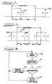
- a typically pulse width modulation signal for use in the control system of Fig. 1 or other control systems.
- a first pulse 100 begins at a time "0" and terminates a period T ON later.
- the remaining portion of the PWM period represents a non-pulse interval illustrated as T OFF .
- a second pulse 102 beings and endures for a set time.
- the termination of the pulse 100 or the pulse 102 may be varied, or modulated, as desired.
- Variation in the length of the pulse within the PWM period provides a duty cycle given as a percent ratio of T ON to T P , the PWM period.
- the leading edge of the pulse in any PWM period coincides with the initiation of the PWM period itself.
- the pulse width modulation frequency in control systems for the continuously variable transmission of the preferred embodiment is limited to approximately 100 Hz. Accordingly, the PWM period illustrates in Fig. 2 would be approximately 10 ms.
- Fig. 3 therein is shown an exemplary waveform illustrative of the double edge modulation for a pulse width modulation control signal in accordance with the present invention.
- the PWM period has remained constant from that of the traditional PWM signal illustrated in Fig. 2.
- the update or sampling period has been cut in half which corresponds to a doubling in update frequency. This may be accomplished as shown by modulation of both the leading edge 104 and the trailing edge 106 of a control pulse 108.
- the duty cycle for each pulse is now calculated as a function of the T ON for each half period of the PWM signal.
- a flow chart for operation of a control system begins at a block 110 at which the system reads the input signals. Based upon the input signals read at the block 110, the system then calculates the appropriate duty cycle at a block 112. The system then advances to a decision block 114 at which it alternates between a first output duty cycle block 116 which controls the ON to OFF pulse edge and a second output duty cycle block 118 which controls the OFF to ON pulse edge. The system then loops back to read the inputs again. Thus, if this system loop is accomplished in 5 ms., a pulse width modulation cycle of 10 ms. will be achieved. However, the duty cycle information will be updated twice per pulse modulation period rather than once per period as with the traditional modulation signal illustrated in Fig. 2.
- the present invention provides a pulse width modulation technique which may be utilized in continuously variable transmission systems, in which it is desired to increase the sampling rate without increasing the on and off rate of particular physical devices, such as electrohydraulic valves.
- the sample rate may be increased and, accordingly, the system response decreased desirably.
Landscapes
- Engineering & Computer Science (AREA)
- General Engineering & Computer Science (AREA)
- Mechanical Engineering (AREA)
- Chemical & Material Sciences (AREA)
- Combustion & Propulsion (AREA)
- Transportation (AREA)
- Control Of Transmission Device (AREA)
- Feedback Control In General (AREA)
- Control Of Driving Devices And Active Controlling Of Vehicle (AREA)
Claims (3)
- Procédé pour produire un signal de commande à largeur d'impulsion modulée qui est délivré à une soupape commandée par largeur d'impulsion modulée dans un système de transmission variable en continu, le signal de commande comprenant un train d'impulsions à une fréquence sélectionnée, comportant les étapes consistant à :
commander l'emplacement du front descendant (106) de l'impulsion dans une première partie de chaque période cyclique, et
commander l'emplacement du front montant (104) de l'impulsion dans une seconde partie de chaque période cyclique. - Procédé selon la revendication 1 comportant les étapes consistant à :
détecter les paramètres sélectionnés du système (à un pavé (110)) ;
calculer un rapport cyclique approprié de l'impulsion (à un pavé 112) ;
terminer l'impulsion (à un pavé 116) à un moment déterminé par les paramètres détectés du système pour définir le front descendant ;
détecter les paramètres sélectionnés du système (à un pavé 110), et
lancer une impulsion (à un pavé 118) à un moment déterminé par les paramètres détectés du système pour définir le front montant. - Procédé selon la revendication 2, dans lequel les étapes consistant à lancer et terminer sont modifiées (à un pavé 114) après chaque étape de détection pendant le fonctionnement du système.
Applications Claiming Priority (2)
| Application Number | Priority Date | Filing Date | Title |
|---|---|---|---|
| US2547787A | 1987-03-13 | 1987-03-13 | |
| US25477 | 1987-03-13 |
Publications (3)
| Publication Number | Publication Date |
|---|---|
| EP0281944A2 EP0281944A2 (fr) | 1988-09-14 |
| EP0281944A3 EP0281944A3 (en) | 1989-07-19 |
| EP0281944B1 true EP0281944B1 (fr) | 1992-09-02 |
Family
ID=21826300
Family Applications (1)
| Application Number | Title | Priority Date | Filing Date |
|---|---|---|---|
| EP88103271A Expired EP0281944B1 (fr) | 1987-03-13 | 1988-03-03 | Technique de modulation par largeur d'impulsion pour une soupape de réglage d'une transmission à variateur |
Country Status (3)
| Country | Link |
|---|---|
| EP (1) | EP0281944B1 (fr) |
| JP (1) | JP2653666B2 (fr) |
| DE (1) | DE3874169T2 (fr) |
Cited By (1)
| Publication number | Priority date | Publication date | Assignee | Title |
|---|---|---|---|---|
| DE19651538C2 (de) * | 1995-12-11 | 2001-10-18 | Jatco Corp | Übertragungsvorrichtung für eine Steuervorrichtung |
Families Citing this family (2)
| Publication number | Priority date | Publication date | Assignee | Title |
|---|---|---|---|---|
| US5115395A (en) * | 1987-03-13 | 1992-05-19 | Borg-Warner Automotive, Inc. | Pulse width modulation technique |
| US5031481A (en) * | 1989-12-08 | 1991-07-16 | Borg-Warner Automotive, Inc. | Electro-hydraulic control system for a dual-pass continuously variable transmission |
Family Cites Families (4)
| Publication number | Priority date | Publication date | Assignee | Title |
|---|---|---|---|---|
| US3803472A (en) * | 1972-12-29 | 1974-04-09 | Gen Electric | Controlled variable time ratio control circuit |
| DE2732298A1 (de) * | 1977-07-16 | 1979-02-01 | Bosch Gmbh Robert | Vorrichtung zur erzeugung einer impulsfolge mit in abhaengigkeit von einer steuerspannung einstellbarem tastverhaeltnis |
| FR2485650A1 (fr) * | 1980-06-25 | 1981-12-31 | Renault | Dispositif electro-hydraulique de modulation de montee en pression serie lors de l'alimentation d'un recepteur |
| JPS624647A (ja) * | 1985-06-29 | 1987-01-10 | Fuji Heavy Ind Ltd | 無段変速機の制御装置 |
-
1988
- 1988-03-03 DE DE8888103271T patent/DE3874169T2/de not_active Expired - Fee Related
- 1988-03-03 EP EP88103271A patent/EP0281944B1/fr not_active Expired
- 1988-03-14 JP JP63060193A patent/JP2653666B2/ja not_active Expired - Lifetime
Cited By (1)
| Publication number | Priority date | Publication date | Assignee | Title |
|---|---|---|---|---|
| DE19651538C2 (de) * | 1995-12-11 | 2001-10-18 | Jatco Corp | Übertragungsvorrichtung für eine Steuervorrichtung |
Also Published As
| Publication number | Publication date |
|---|---|
| EP0281944A3 (en) | 1989-07-19 |
| EP0281944A2 (fr) | 1988-09-14 |
| DE3874169T2 (de) | 1993-01-14 |
| JP2653666B2 (ja) | 1997-09-17 |
| JPS63251336A (ja) | 1988-10-18 |
| DE3874169D1 (de) | 1992-10-08 |
Similar Documents
| Publication | Publication Date | Title |
|---|---|---|
| EP0281850B1 (fr) | Technique de commande de rapports pour une transmission à variation continue | |
| EP0281849B1 (fr) | Système de commande d'embrayage pour une transmission à variation continue | |
| EP0310277B1 (fr) | Détection et compensation du glissement en régime stationnaire pour une transmission de véhicule à moteur | |
| US5737979A (en) | Method of calibrating clutches in a transmission | |
| US4476746A (en) | Hydraulic regulator for a V-belt type continuously variable transmission for vehicles | |
| US4470117A (en) | Control system for a continuously variable transmission for vehicles | |
| EP0436978A2 (fr) | Méthode pour commander des changements de vitesses dans une transmission automatique | |
| EP0435373B1 (fr) | Méthode pour commander des changements de vitesses dans une transmission automatique | |
| EP0385438B1 (fr) | Réglage de la pression pour la transmission automatique d'un véhicule à moteur | |
| US5400678A (en) | Line pressure optimization in an automatic transmission | |
| EP0467519B1 (fr) | Technique de modulation par largeur d'impulsion | |
| EP0635391A2 (fr) | Algorithme d'identification du point de contact pour dispositif de commande d'embrayage automatique | |
| US5144265A (en) | Pulse width modulation technique | |
| EP0276022B2 (fr) | Système de commande pour l'embrayage d'un véhicule | |
| EP0239365B1 (fr) | Commande du rapport d'une transmission continue | |
| US5950789A (en) | End of fill detector for a fluid actuated clutch | |
| JP3625868B2 (ja) | 自動車におけるギヤの検出方法とその装置およびコンバータ増幅度の検出方法とその装置 | |
| EP0415523B1 (fr) | Système de transmission à variation continue avec système de commande d'embrayage | |
| US5189611A (en) | Temperature compensation technique for a continuously variable transmission control system | |
| EP0281944B1 (fr) | Technique de modulation par largeur d'impulsion pour une soupape de réglage d'une transmission à variateur | |
| JP2002138879A (ja) | 車両用無段変速機のライン圧制御装置。 | |
| EP0281947B1 (fr) | Technique de compensation de température pour une transmission continue de vitesse | |
| EP0435372B1 (fr) | Méthode pour commander un changement de vitesse dans une transmission automatique | |
| JP2000145938A (ja) | トランスミッションクラッチの充填時間決定方法 | |
| EP0240281B1 (fr) | Système de commande pour un embrayage électromagnétique d'un véhicule automobile |
Legal Events
| Date | Code | Title | Description |
|---|---|---|---|
| PUAI | Public reference made under article 153(3) epc to a published international application that has entered the european phase |
Free format text: ORIGINAL CODE: 0009012 |
|
| AK | Designated contracting states |
Kind code of ref document: A2 Designated state(s): DE FR GB IT SE |
|
| PUAL | Search report despatched |
Free format text: ORIGINAL CODE: 0009013 |
|
| AK | Designated contracting states |
Kind code of ref document: A3 Designated state(s): DE FR GB IT SE |
|
| 17P | Request for examination filed |
Effective date: 19900104 |
|
| 17Q | First examination report despatched |
Effective date: 19910611 |
|
| 17Q | First examination report despatched |
Effective date: 19911128 |
|
| GRAA | (expected) grant |
Free format text: ORIGINAL CODE: 0009210 |
|
| AK | Designated contracting states |
Kind code of ref document: B1 Designated state(s): DE FR GB IT SE |
|
| PG25 | Lapsed in a contracting state [announced via postgrant information from national office to epo] |
Ref country code: SE Effective date: 19920902 |
|
| ITF | It: translation for a ep patent filed | ||
| REF | Corresponds to: |
Ref document number: 3874169 Country of ref document: DE Date of ref document: 19921008 |
|
| ET | Fr: translation filed | ||
| PG25 | Lapsed in a contracting state [announced via postgrant information from national office to epo] |
Ref country code: GB Effective date: 19930303 |
|
| PLBE | No opposition filed within time limit |
Free format text: ORIGINAL CODE: 0009261 |
|
| STAA | Information on the status of an ep patent application or granted ep patent |
Free format text: STATUS: NO OPPOSITION FILED WITHIN TIME LIMIT |
|
| 26N | No opposition filed | ||
| GBPC | Gb: european patent ceased through non-payment of renewal fee |
Effective date: 19930303 |
|
| PGFP | Annual fee paid to national office [announced via postgrant information from national office to epo] |
Ref country code: FR Payment date: 19970307 Year of fee payment: 10 |
|
| PGFP | Annual fee paid to national office [announced via postgrant information from national office to epo] |
Ref country code: DE Payment date: 19970326 Year of fee payment: 10 |
|
| PG25 | Lapsed in a contracting state [announced via postgrant information from national office to epo] |
Ref country code: FR Free format text: THE PATENT HAS BEEN ANNULLED BY A DECISION OF A NATIONAL AUTHORITY Effective date: 19980331 |
|
| PG25 | Lapsed in a contracting state [announced via postgrant information from national office to epo] |
Ref country code: DE Free format text: LAPSE BECAUSE OF NON-PAYMENT OF DUE FEES Effective date: 19981201 |
|
| REG | Reference to a national code |
Ref country code: FR Ref legal event code: ST |
|
| PG25 | Lapsed in a contracting state [announced via postgrant information from national office to epo] |
Ref country code: IT Free format text: LAPSE BECAUSE OF NON-PAYMENT OF DUE FEES Effective date: 20050303 |