EP0281850B1 - Technique de commande de rapports pour une transmission à variation continue - Google Patents
Technique de commande de rapports pour une transmission à variation continue Download PDFInfo
- Publication number
- EP0281850B1 EP0281850B1 EP88102738A EP88102738A EP0281850B1 EP 0281850 B1 EP0281850 B1 EP 0281850B1 EP 88102738 A EP88102738 A EP 88102738A EP 88102738 A EP88102738 A EP 88102738A EP 0281850 B1 EP0281850 B1 EP 0281850B1
- Authority
- EP
- European Patent Office
- Prior art keywords
- signal
- ratio
- engine speed
- belt ratio
- error
- Prior art date
- Legal status (The legal status is an assumption and is not a legal conclusion. Google has not performed a legal analysis and makes no representation as to the accuracy of the status listed.)
- Expired - Lifetime
Links
Images



Classifications
-
- F—MECHANICAL ENGINEERING; LIGHTING; HEATING; WEAPONS; BLASTING
- F16—ENGINEERING ELEMENTS AND UNITS; GENERAL MEASURES FOR PRODUCING AND MAINTAINING EFFECTIVE FUNCTIONING OF MACHINES OR INSTALLATIONS; THERMAL INSULATION IN GENERAL
- F16H—GEARING
- F16H61/00—Control functions within control units of change-speed- or reversing-gearings for conveying rotary motion ; Control of exclusively fluid gearing, friction gearing, gearings with endless flexible members or other particular types of gearing
- F16H61/66—Control functions within control units of change-speed- or reversing-gearings for conveying rotary motion ; Control of exclusively fluid gearing, friction gearing, gearings with endless flexible members or other particular types of gearing specially adapted for continuously variable gearings
- F16H61/662—Control functions within control units of change-speed- or reversing-gearings for conveying rotary motion ; Control of exclusively fluid gearing, friction gearing, gearings with endless flexible members or other particular types of gearing specially adapted for continuously variable gearings with endless flexible members
- F16H61/66254—Control functions within control units of change-speed- or reversing-gearings for conveying rotary motion ; Control of exclusively fluid gearing, friction gearing, gearings with endless flexible members or other particular types of gearing specially adapted for continuously variable gearings with endless flexible members controlling of shifting being influenced by a signal derived from the engine and the main coupling
-
- B—PERFORMING OPERATIONS; TRANSPORTING
- B60—VEHICLES IN GENERAL
- B60W—CONJOINT CONTROL OF VEHICLE SUB-UNITS OF DIFFERENT TYPE OR DIFFERENT FUNCTION; CONTROL SYSTEMS SPECIALLY ADAPTED FOR HYBRID VEHICLES; ROAD VEHICLE DRIVE CONTROL SYSTEMS FOR PURPOSES NOT RELATED TO THE CONTROL OF A PARTICULAR SUB-UNIT
- B60W10/00—Conjoint control of vehicle sub-units of different type or different function
- B60W10/02—Conjoint control of vehicle sub-units of different type or different function including control of driveline clutches
-
- B—PERFORMING OPERATIONS; TRANSPORTING
- B60—VEHICLES IN GENERAL
- B60W—CONJOINT CONTROL OF VEHICLE SUB-UNITS OF DIFFERENT TYPE OR DIFFERENT FUNCTION; CONTROL SYSTEMS SPECIALLY ADAPTED FOR HYBRID VEHICLES; ROAD VEHICLE DRIVE CONTROL SYSTEMS FOR PURPOSES NOT RELATED TO THE CONTROL OF A PARTICULAR SUB-UNIT
- B60W10/00—Conjoint control of vehicle sub-units of different type or different function
- B60W10/04—Conjoint control of vehicle sub-units of different type or different function including control of propulsion units
-
- B—PERFORMING OPERATIONS; TRANSPORTING
- B60—VEHICLES IN GENERAL
- B60W—CONJOINT CONTROL OF VEHICLE SUB-UNITS OF DIFFERENT TYPE OR DIFFERENT FUNCTION; CONTROL SYSTEMS SPECIALLY ADAPTED FOR HYBRID VEHICLES; ROAD VEHICLE DRIVE CONTROL SYSTEMS FOR PURPOSES NOT RELATED TO THE CONTROL OF A PARTICULAR SUB-UNIT
- B60W10/00—Conjoint control of vehicle sub-units of different type or different function
- B60W10/10—Conjoint control of vehicle sub-units of different type or different function including control of change-speed gearings
- B60W10/101—Infinitely variable gearings
-
- B—PERFORMING OPERATIONS; TRANSPORTING
- B60—VEHICLES IN GENERAL
- B60W—CONJOINT CONTROL OF VEHICLE SUB-UNITS OF DIFFERENT TYPE OR DIFFERENT FUNCTION; CONTROL SYSTEMS SPECIALLY ADAPTED FOR HYBRID VEHICLES; ROAD VEHICLE DRIVE CONTROL SYSTEMS FOR PURPOSES NOT RELATED TO THE CONTROL OF A PARTICULAR SUB-UNIT
- B60W10/00—Conjoint control of vehicle sub-units of different type or different function
- B60W10/10—Conjoint control of vehicle sub-units of different type or different function including control of change-speed gearings
- B60W10/101—Infinitely variable gearings
- B60W10/107—Infinitely variable gearings with endless flexible members
-
- B—PERFORMING OPERATIONS; TRANSPORTING
- B60—VEHICLES IN GENERAL
- B60W—CONJOINT CONTROL OF VEHICLE SUB-UNITS OF DIFFERENT TYPE OR DIFFERENT FUNCTION; CONTROL SYSTEMS SPECIALLY ADAPTED FOR HYBRID VEHICLES; ROAD VEHICLE DRIVE CONTROL SYSTEMS FOR PURPOSES NOT RELATED TO THE CONTROL OF A PARTICULAR SUB-UNIT
- B60W30/00—Purposes of road vehicle drive control systems not related to the control of a particular sub-unit, e.g. of systems using conjoint control of vehicle sub-units
- B60W30/18—Propelling the vehicle
- B60W30/1819—Propulsion control with control means using analogue circuits, relays or mechanical links
-
- B—PERFORMING OPERATIONS; TRANSPORTING
- B60—VEHICLES IN GENERAL
- B60W—CONJOINT CONTROL OF VEHICLE SUB-UNITS OF DIFFERENT TYPE OR DIFFERENT FUNCTION; CONTROL SYSTEMS SPECIALLY ADAPTED FOR HYBRID VEHICLES; ROAD VEHICLE DRIVE CONTROL SYSTEMS FOR PURPOSES NOT RELATED TO THE CONTROL OF A PARTICULAR SUB-UNIT
- B60W30/00—Purposes of road vehicle drive control systems not related to the control of a particular sub-unit, e.g. of systems using conjoint control of vehicle sub-units
- B60W30/18—Propelling the vehicle
- B60W30/19—Improvement of gear change, e.g. by synchronisation or smoothing gear shift
-
- B—PERFORMING OPERATIONS; TRANSPORTING
- B60—VEHICLES IN GENERAL
- B60W—CONJOINT CONTROL OF VEHICLE SUB-UNITS OF DIFFERENT TYPE OR DIFFERENT FUNCTION; CONTROL SYSTEMS SPECIALLY ADAPTED FOR HYBRID VEHICLES; ROAD VEHICLE DRIVE CONTROL SYSTEMS FOR PURPOSES NOT RELATED TO THE CONTROL OF A PARTICULAR SUB-UNIT
- B60W50/00—Details of control systems for road vehicle drive control not related to the control of a particular sub-unit, e.g. process diagnostic or vehicle driver interfaces
- B60W2050/0001—Details of the control system
- B60W2050/0002—Automatic control, details of type of controller or control system architecture
- B60W2050/0008—Feedback, closed loop systems or details of feedback error signal
- B60W2050/001—Proportional integral [PI] controller
-
- B—PERFORMING OPERATIONS; TRANSPORTING
- B60—VEHICLES IN GENERAL
- B60W—CONJOINT CONTROL OF VEHICLE SUB-UNITS OF DIFFERENT TYPE OR DIFFERENT FUNCTION; CONTROL SYSTEMS SPECIALLY ADAPTED FOR HYBRID VEHICLES; ROAD VEHICLE DRIVE CONTROL SYSTEMS FOR PURPOSES NOT RELATED TO THE CONTROL OF A PARTICULAR SUB-UNIT
- B60W50/00—Details of control systems for road vehicle drive control not related to the control of a particular sub-unit, e.g. process diagnostic or vehicle driver interfaces
- B60W2050/0001—Details of the control system
- B60W2050/0019—Control system elements or transfer functions
- B60W2050/0022—Gains, weighting coefficients or weighting functions
-
- B—PERFORMING OPERATIONS; TRANSPORTING
- B60—VEHICLES IN GENERAL
- B60W—CONJOINT CONTROL OF VEHICLE SUB-UNITS OF DIFFERENT TYPE OR DIFFERENT FUNCTION; CONTROL SYSTEMS SPECIALLY ADAPTED FOR HYBRID VEHICLES; ROAD VEHICLE DRIVE CONTROL SYSTEMS FOR PURPOSES NOT RELATED TO THE CONTROL OF A PARTICULAR SUB-UNIT
- B60W50/00—Details of control systems for road vehicle drive control not related to the control of a particular sub-unit, e.g. process diagnostic or vehicle driver interfaces
- B60W2050/0001—Details of the control system
- B60W2050/0043—Signal treatments, identification of variables or parameters, parameter estimation or state estimation
- B60W2050/0052—Filtering, filters
-
- B—PERFORMING OPERATIONS; TRANSPORTING
- B60—VEHICLES IN GENERAL
- B60W—CONJOINT CONTROL OF VEHICLE SUB-UNITS OF DIFFERENT TYPE OR DIFFERENT FUNCTION; CONTROL SYSTEMS SPECIALLY ADAPTED FOR HYBRID VEHICLES; ROAD VEHICLE DRIVE CONTROL SYSTEMS FOR PURPOSES NOT RELATED TO THE CONTROL OF A PARTICULAR SUB-UNIT
- B60W2510/00—Input parameters relating to a particular sub-units
- B60W2510/02—Clutches
- B60W2510/0241—Clutch slip, i.e. difference between input and output speeds
-
- B—PERFORMING OPERATIONS; TRANSPORTING
- B60—VEHICLES IN GENERAL
- B60W—CONJOINT CONTROL OF VEHICLE SUB-UNITS OF DIFFERENT TYPE OR DIFFERENT FUNCTION; CONTROL SYSTEMS SPECIALLY ADAPTED FOR HYBRID VEHICLES; ROAD VEHICLE DRIVE CONTROL SYSTEMS FOR PURPOSES NOT RELATED TO THE CONTROL OF A PARTICULAR SUB-UNIT
- B60W2510/00—Input parameters relating to a particular sub-units
- B60W2510/06—Combustion engines, Gas turbines
- B60W2510/0638—Engine speed
-
- B—PERFORMING OPERATIONS; TRANSPORTING
- B60—VEHICLES IN GENERAL
- B60W—CONJOINT CONTROL OF VEHICLE SUB-UNITS OF DIFFERENT TYPE OR DIFFERENT FUNCTION; CONTROL SYSTEMS SPECIALLY ADAPTED FOR HYBRID VEHICLES; ROAD VEHICLE DRIVE CONTROL SYSTEMS FOR PURPOSES NOT RELATED TO THE CONTROL OF A PARTICULAR SUB-UNIT
- B60W2540/00—Input parameters relating to occupants
- B60W2540/10—Accelerator pedal position
-
- B—PERFORMING OPERATIONS; TRANSPORTING
- B60—VEHICLES IN GENERAL
- B60W—CONJOINT CONTROL OF VEHICLE SUB-UNITS OF DIFFERENT TYPE OR DIFFERENT FUNCTION; CONTROL SYSTEMS SPECIALLY ADAPTED FOR HYBRID VEHICLES; ROAD VEHICLE DRIVE CONTROL SYSTEMS FOR PURPOSES NOT RELATED TO THE CONTROL OF A PARTICULAR SUB-UNIT
- B60W2540/00—Input parameters relating to occupants
- B60W2540/10—Accelerator pedal position
- B60W2540/106—Rate of change
-
- B—PERFORMING OPERATIONS; TRANSPORTING
- B60—VEHICLES IN GENERAL
- B60W—CONJOINT CONTROL OF VEHICLE SUB-UNITS OF DIFFERENT TYPE OR DIFFERENT FUNCTION; CONTROL SYSTEMS SPECIALLY ADAPTED FOR HYBRID VEHICLES; ROAD VEHICLE DRIVE CONTROL SYSTEMS FOR PURPOSES NOT RELATED TO THE CONTROL OF A PARTICULAR SUB-UNIT
- B60W2710/00—Output or target parameters relating to a particular sub-units
- B60W2710/02—Clutches
- B60W2710/021—Clutch engagement state
- B60W2710/023—Clutch engagement rate
-
- F—MECHANICAL ENGINEERING; LIGHTING; HEATING; WEAPONS; BLASTING
- F16—ENGINEERING ELEMENTS AND UNITS; GENERAL MEASURES FOR PRODUCING AND MAINTAINING EFFECTIVE FUNCTIONING OF MACHINES OR INSTALLATIONS; THERMAL INSULATION IN GENERAL
- F16H—GEARING
- F16H59/00—Control inputs to control units of change-speed- or reversing-gearings for conveying rotary motion
- F16H59/14—Inputs being a function of torque or torque demand
- F16H59/18—Inputs being a function of torque or torque demand dependent on the position of the accelerator pedal
- F16H2059/183—Rate of change of accelerator position, i.e. pedal or throttle change gradient
-
- F—MECHANICAL ENGINEERING; LIGHTING; HEATING; WEAPONS; BLASTING
- F16—ENGINEERING ELEMENTS AND UNITS; GENERAL MEASURES FOR PRODUCING AND MAINTAINING EFFECTIVE FUNCTIONING OF MACHINES OR INSTALLATIONS; THERMAL INSULATION IN GENERAL
- F16H—GEARING
- F16H59/00—Control inputs to control units of change-speed- or reversing-gearings for conveying rotary motion
- F16H59/14—Inputs being a function of torque or torque demand
- F16H59/18—Inputs being a function of torque or torque demand dependent on the position of the accelerator pedal
Definitions
- the present invention generally relates to the continuously variable transmission art. More particularly, the present invention relates to belt ratio control for continuously variable transmissions and to providing desired belt ratio control in particular driving circumstances as defined in the first part of claim 1 and 7 respectively.
- CVT′S continuously variable transmissions
- U. S. Patent No. 4,522,086, and U. S. Patent No. 4,458,318, which is the generic prior art.
- These patents generally describe the mechanics and controls for a CVT system utilizing two adjustable pulleys, each pulley having at least one sheave which is axially fixed and another sheave which is axially movable relative to the first sheave.
- a flexible belt of metal or elastomeric material intercouples the pulleys.
- the interior faces of the pulley sheaves are beveled or chamfered.
- the displaceable sheave includes a fluid constraining chamber for receiving fluid to move the sheave and thus change the effective pulley diameter; as fluid is exhausted from the chamber, the pulley diameter changes in the opposite sense.
- the effective diameter of one pulley is adjusted in one direction as the effective diameter of the second pulley is varied in the opposite direction, thereby effecting a change in the drive ratio between the input shaft coupled to an input pulley and an output shaft coupled to an output pulley.
- the ratio changes continuously as the pulley diameters vary.
- Such transmissions frequently are referred to in the art as a continuously variable transmission, CVT.
- U. S. Patent No. 4,648,496 further describes control logic techniques for regulating pressure at a clutch in a CVT system to provide the desired torque transfer from an engine to a vehicle drive line.
- clutch control depends on logical recognition of one of a number of operating modes.
- a related, co-pending application entitled “Continuously Variable Transmission Clutch Control System”, Serial No. 25,391, filed March 13, 1987 (EP-A-281849) assigned to the assignee of the present application discloses an improved clutch controller for use in CVT applications.
- a second, related, co-pending application entitled “Special Start Technique For Continuously Variable Transmission Clutch Control”, Serial No. 25,476, filed March 13, 1987 (EP-A-283787) assigned to the assignee of the present application discloses a unique technique for regulating the clutch pressure control signal in a CVT system during selected driving conditions, e.g. skidding on ice.
- a principal object of the present invention lies in providing an improved ratio control technique which generally overcomes the deficiencies of the prior art.
- a more specific object of the present invention lies in the provision of belt ratio control techniques for continuously variable transmission driven vehicles during a variety of driving conditions.
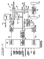
- a throttle signal 10 controls the operation of an engine 12 which transmits torque via shaft 14 to a primary pulley 16 in a CVT 18.
- a flywheel and damping arrangement may be included on shaft 14 between the engine 12 and the primary pulley 16.
- a metal or elastomeric belt 20 connects the primary pulley 16 to a secondary pulley 22 to transmit torque to a second shaft 24.
- a pump 26 may also be driven by the first shaft 14 to provide line pressure for the hydraulic system and the controls of the CVT 18.
- the second shaft 24 drives the input to a clutch 28 which in turn provides a torque to a third shaft 30.
- the third shaft 30 drives a reduction differential gear arrangement 32 as a drive line to provide power to the vehicle wheels 34.
- an electronic controller 36 receives throttle, engine speed, clutch input speed, clutch output speed, clutch pressure, temperature, driver demand, idle, shift lever and other information input signals as shown at the left of FIG. 1.
- the electronic controller 36 operates in a logical fashion to provide a ratio control signal on a line 38, a line pressure control signal on a line 40 and a clutch control signal on a line 42.
- the signal on the line 38 to a ratio control valve 44 controls the hydraulic pressure on a line 46 to the primary pulley 16 of the CVT 18 to control the ratio between the primary pulley 16 and the secondary pulley 22, i.e. , the belt ratio.
- the signal on the line 40 communicates with a line pressure regulator 48 which via a line 50 provides line pressure from flow delivered by pump 26 to the ratio control valve 44 and to a clutch control valve 52.
- the output of the line pressure regulator on the line 50 also controls the pressure at the secondary pulley 22 to ensure that the belt 20 does not slip.
- the output signal on the line 42 to the clutch control valve 52 controls the output of the clutch control valve 52 on a line 54 to the manual and servo valves 56 which controls the fluid flow on the line 58 to the clutch 28. This is the signal which controls or which provides the pressure at the clutch 28 and hence regulates the torque transfer from the second shaft 24 to the third shaft 30.
- a shift lever signal on a line 60 provides an additional control of the manual and servo valves 56.
- the shift lever signal on the line 60 indicates that the vehicle is in a neutral or park mode
- the manual control within the valve arrangement 56 is closed. This prevents fluid from flowing to the clutch 28 and thus prevents any torque transfer through the clutch 28 when the vehicle is in the neutral mode.
- the ratio of NE to NCI will correspond to and provide a measure of the transmission belt ratio.
- the difference between NCI and NCO correspondingly provides a measure of the slippage at the clutch 28.
- NCI equals NCO, the clutch 28 should be locked-up with no slippage.
- the electronic controller 36 implements the control functions for controlling the hydraulic fluid flow to the primary sheave actuator 16 by means of a pulse width modulation (PWM)-operated electrohydraulic control valve 44.
- PWM pulse width modulation
- the resultant pressure from this flow moves the primary actuator which forces the belt to move in the primary and secondary pulleys. Movement of the belt creates a ratio change in the CVT.
- the present invention envisions a number of control modes for operation of ratio control by means of the electronic controller 36 and the ratio control valve 44.
- control modes there are four control modes, namely,
- ENGINE SPEED CONTROL The system performs closed loop control of the actual engine speed to an engine speed set point which is determined from a schedule based on throttle position and vehicle speed. Alternately, the system may use a closed loop control of the actual engine speed to a set point which is obtained from external strategy.
- BELT RATIO CONTROL The system performs closed loop control of the actual belt ratio as determined by the engine speed (CVT input speed) divided by the clutch input speed. As explained above this is also given by the ratio of NE to NCI.
- the set point can be input to the control system, based on external criteria, or once this control mode is entered, the system may use the current ratio as the set point. This would cause the CVT to maintain this ratio once this mode is entered.
- CLUTCH INPUT SPEED CONTROL The system performs closed loop control of the actual clutch input speed.
- the set point can be input to this control system, based on external criteria, or once this control mode is entered, the system may use the clutch output speed as the set point. This would cause the CVT to synchronize the clutch input and the clutch output speed to facilitate clutch re-engagement.
- This control mode can only be used when the clutch is in a non-torque carrying mode.
- OPEN LOOP CONTROL By sending out a full-on duty cycle or a full-off duty cycle, the open loop mode will place the CVT in full low ratio or maximum overdrive at the maximum rate at which the sheaves can move. Full low and maximum overdrive ratios are determined by the physical limits of the sheaves in the primary and secondary pulleys.
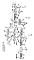
- the controller of FIG. 2 generally comprises a proportional control section 100, an integrator-lead calculation section 102 and a nominal null control section 104.
- the proportional control section in turn, generally comprises an engine speed control loop 106, a belt ratio control loop 108 and a clutch speed control loop 110. Only one of these loops functions at any time dependant on the parameter being controlled. In each of these three loops, a particular gain schedule is utilized to provide the loop control parameters. These schedules are illustrated in an exemplary fashion in FIGs. 4, 5 and 6. Also, the engine speed control loop 106 utilizes a set point schedule and a limiter schedule illustrated generally in an exemplary fashion in FIGs. 7 and 8, respectively.
- the proportional gain portion 100 attempts to maintain a constant open loop gain to yield a constant closed loop system response for all parameter conditions.
- the particular gain schedules for each of the proportional control loops 106, 108 and 110 facilitate this operation. Once a gain is determined from the schedules, it is multiplied by the nominal loop gain. This provides the loop gain by which the error signal is multiplied to provide an output error signal to the integrator-lead portion of the controller 102.
- the engine speed control loop 106 receives a filtered engine speed set point, n esf at a line 121.
- the actual engine speed, n e from a line 122 is then subtracted from the engine speed set point on line 121 at a summing junction 124.
- This provides a first error signal e1 to a variable gain function block 126 which provides a multiplication factor to the nominal control loop gain as a function of the engine speed received on the line 122 (also received at the gain control box 126).
- This provides one second error signal e2 on a line 128 for provision to the integrator lead section 102 when the engine speed control loop has been selected.
- the belt ratio control loop 108 illustrated in FIG. 102 receives a belt ratio set point, R bs at a line 130.
- a summing junction 132 then subtracts the actual belt ratio signal, R b , received on a line 134 to generate a first error signal, e1.
- a gain function block 136 which also provides a multiplication factor to the nominal control loop gain, then generates a belt ratio gain, Kar, as a function of the actual belt ratio received at line 134.
- the belt ratio control loop 108 then multiplies the signal e1 from summing junction 132 to provide further second error signal e2 on a line 138 to the integrator lead section 102 when the belt ratio control loop has been selected.
- the clutch input speed controller 110 receives a clutch input speed set point at a line 140.
- a summing junction 142 then subtracts the actual clutch input speed received at a line 144 to generate a first error signal e1.
- the error signal e1 from the summing junction 142 is then multiplied by a gain factor determined as a product of the nominal gain times the gain determined from a schedule at a block 146 as a function of the actual clutch input speed received from line 144.
- the integrator-lead control section 102 operates to force any steady-state error in the controller system to be zero.
- the integrator gain desirably comprises a relatively small value so as to yield a slow response which does not affect the system dynamics. This avoids the possibility of generating an undesired instability in the control system.
- the controller may adjust the null of the system. This allows it to track slowly varying changes in the system and maintain the steady-state error at zero.
- the integrator lead section 102 illustrated in FIG. 2 comprises an integrator function block 154 which receives one of said second error signals e2 from a line 156 which may be connected to one of lines 128, 138 and 152 depending upon which of the three proportional gain control loops has been selected for control of the system.
- the integrator function block 154 performs an integration shown by the transfer function therein to provide a signal to an integrator limit function 158 to provide an output signal x1 at a line 160.
- the integrator limit function embodied in the block 158 of FIG. 2 prevents the digital implementation of the integrator 154 from saturating the input to the pulse width modulation generator at the output of the control system. Accordingly, the output of the integrator must be compared with upper and lower limits to keep it within an acceptable range for the pulse width generator.
- An integrator logic block 162 controls the operation of the integrator 154.
- An integrator logic block 162 receives a belt ratio signal at a line 164 and a throttle signal at a line 166.
- Certain operating conditions may be utilized to determine whether the integrator should be allowed to function or hold its current value. In the present embodiment. these conditions are reflected in the belt ratio received at the line 164 and the throttle position received at the line 166. If the belt ratio is less than a predetermined value close to the actual overdrive ratio or greater than a predetermined value close to the actual full low ratio, the integrator does not function, but is held at its current value. This prevents the integrator from calculating an incorrect steady-state error correction signal when the pulley sheaves achieve their physical displacement limits.
- the integrator logic monitors the throttle position. If the throttle position is less than a predetermined value, the integrator is not allowed to function but is held at its present state. This allows the control system to distinguish between power-off and power-on conditions.
- the integrator 154 typically will be provided with an initial condition.
- this initial condition (not illustrated) is chosen as zero.
- the system therein receives a nominal null input signal, N0, the error signal from the proportional gain loop section 100, e2, and the output of the integrator control 102, X1. This portion of the system then provides an output signal e4.
- a summing junction 168 combines the output of the integrator, X1, with the second error signal, e2, from the proportional gain loop section 100.
- a second summing junction 170 then combines the output, e3, of the first summing junction 168, with a nominal null input N0, from a line 172 to form the output signal, e4.
- the output signal, e4 then controls the duty cycle of the signal to drive the PWM controlled electrohydraulic valve which supplies the flow to the sheave of the primary pulley.
- null steady-state correction term
- the null portion 104 of FIG. 2 also provides an actual null output, N.
- a null may be defined as the value of the duty cycle for the ratio control valve corresponding to those conditions in which the steady-state error is zero.
- the nominal null signal combined with the output of the integrator combined with the error signal e2 provides the output signal from the system in FIG. 2. Additionally, the output of the integrator may be viewed as that signal which must be added to a nominal null signal to achieve the actual null condition. Accordingly, an actual null signal, N, may be obtained by combining the nominal null input signal with the output of the integrator section 102.
- a logical generation of an engine speed set point may be provided for use in the engine speed control loop 106.
- a throttle signal on a line 112 determines the operating point as a function of set point schedule 114, which is shown in the preferred embodiment as a four line segment interpretation of throttle illustrated generally in FIG. 7.
- the output of the set point schedule 114 is provided to a limiter 116 which in conjunction with a signal representative of the vehicle speed, NCO, on a line 118 provides an engine speed set point to a set point filter 120.
- the limiter 116 limits the set point based on the vehicle speed.
- the set point filter 120 slows the rate of change of the set point to improve the drivability or feel of the vehicle.
- sudden increases in throttle yield sudden increases in the engine speed setpoint which result in a relatively rapid speed of ratio change which cause the vehicle to experience a "torque-drop" until the actual engine speed increases to the desired set point. This occurs because the total torque (engine and vehicle) accelerates the engine rather than the vehicle, to a higher speed. This results in a noticeable hesitation of the vehicle when the throttle is suddenly applied, an experience which the driver does not expect.
- the filter parameters may be chosen to empirically improve the drivability of the vehicle. Because the filter slows the rate of change, the particular parameters may be selected to provide the desired rate of change in response to throttle changes.
- the actual engine speed may be utilized as the initial condition for the set point filter 120.
- the filter is allowed to run as soon as the clutch of the CVT vehicle is locked-up.
- This condition or "mode” is referred to as Drive Mode and is explained in more detail in the said co-pending applications U. S. Serial Nos. 25,476 and 25,391, both filed March 13, 1987 (EP-A-283 787 and EP-A-281 849).
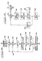
- the system begins at a start block 200 and advances to a next block 202 at which initial conditions are set, specifically, the output of the integrator is set to zero, the open loop and initial condition flags are set and the set point flag is reset.
- the system then advances to a select mode step at a block 204 at which the open loop, ratio, engine speed set point and set point flags are set for the appropriate mode operation set forth above. For example, if the system is to operate in the open loop mode, the open loop (OL) flag is set.
- the set point (SP) flag is set to correspond to whether the system is to go to and maintain full low or full overdrive ratio as explained more fully below.
- the system determines whether a mode change has occurred. If yes, then the initial condition flag is set in block 208. This provides the desired smooth transitions by ensuring that the system will use the appropriate initial conditions, for the setpoints and filter. If no, then the system determines whether the open loop flag is set in block 210. If yes, the system determines whether the set point flag has been set at a block 212. If yes, the controller will place the transmission in full overdrive by setting e4, the output signal, to a minimum at a block 214. The system then branches to convert that signal for the appropriate duty cycle as explained below in conjunction with FIG. 3B.
- the controller will place the transmission in full low by setting e4 to a maximum at a block 216.
- the system then branches to convert the e4 output signal to the appropriate duty cycle.
- the system determines whether the ratio control flag has been set at a block 218. If yes, the system determines whether the set point flag has been set at a block 220. If yes, then the system specifies the belt ratio set point (Rbs) from an external source at a block 222 and branches to provide the gain and error function as shown by the functional block 224.
- Rbs belt ratio set point
- the system determines whether the initial condition flag has been set at a block 226. If yes, then at a block 228 the system sets the belt ratio set point to the actual belt ratio and resets the initial condition flag. The system then advances to provide the gain and error functions shown at the functional block 224. If the initial condition flag has not been set as determined at the decision block 226, then the system advances directly to provide the gain and error functions at the block 224 and maintains the current belt ratio.
- the system determines whether the engine speed set point (ESP) flag has been set at a block 230. If yes, then the system determines whether the set point flag has been set at a block 232. If yes, then the engine set point may be specified from an external source as shown at a block 234. If no, then the system looks to the ratio schedule as shown at a block 236 to provide the engine set point. Once either an external engine speed set point or a set point from the ratio schedule has been determined by the block 234 or the block 236, the system advances to block 237 to determine if the IC flag is set. If the IC flag is not set, the system proceeds to the setpoint filter, block 238. If the IC flag is set, the setpoint filter initial condition is set equal to a filtered version of the actual engine speed, NEFIL and resets the IC flag at block 239. The system then branches to the setpoint filter, block 238.
- ESP engine speed set point
- the form of this filter in the frequency domain is: where wsf is the cutoff frequency of the filter.
- the discrete form of the filter is:
- the system sets the clutch input speed (CIS) flag at a block 242.
- the system determines whether the set point flag has been set at a decision block 244. If yes, then the clutch input speed may be specified at a block 246. If yes, then the clutch input speed may be specified at a block 246. If no, then the clutch input speed setpoint is set equal to the clutch output speed at a block 248. Once a clutch input speed set point has been set at either block 246 or block 248, the system advances to the functional block 250 to provide the gain and error functions.
- the integrator output and null functions are shown generally at a functional block 252.
- the system determines whether the belt ratio is less than some lower limit belt ratio at a decision block 254. If no, the system advances. If yes, then the system skips the integrator function by branching to a line 256 and proceeds to convert the e4 or output signals to the appropriate duty cycle.
- the system determines at a decision block 258 whether the belt ratio is greater than the upper limit for the belt ratio. If yes, then some system branches to the line 156 and proceeds to convert the e4 signal for the appropriate duty cycle.
- the system determines at a decision block 260 whether the throttle setting is less than a lower limit throttle setting. If yes, the system branches to the line 256 and skips the integrator functions.
- the decision blocks 254, 258 and 260 in conjunction with the line 256 which routes pass the integrator block 262 corresponds to the logical function of the block 162 of FIG. 2.
- the system holds the current value at the integrator and advances directly to generation of the appropriate duty cycle signal.
- the system determines a decision block 264 whether the integrator output is less than a lower limit for the integrator. If yes, at a block 266, the system sets the integrator output at the lower limit. If no, the system then advances to a next decision block 268 to determine whether the integrator output is greater than the upper limit for the integrator. If yes, the system sets the integrator output at its upper limit at a block 270 and advances to convert the output signal to a duty cycle with limits between a minimum and a maximum as shown at block 272. The system then branches back to the mode determination block 204 illustrated in FIG. 3A and repeats.
- FIG. 3C there is shown an alternate embodiment for the engine set point control loop.
- the decision blocks 230 and 232, and the functions block 234 and 240 are common to the embodiments of both FIG. 3A and FIG. 3C.
- the system illustrated on FIG. 3C determines that the set point flag has not been set, the system advances to a ratio schedule block 274, similar to the ratio schedule block 236 of FIG. 3A.
- the system determines an upper limit on the engine speed setpoint at a block 276 as a function of vehicle speed and advances to a block 278 which determines the engine speed set point as the lesser of the values from the ratio schedule of block 274 and the upper limit of the block 276.
- the system then advances to the gain and error functional block 240.
- the embodiment of FIG. 3C is shown in FIG. 2.
- the function of the block 278 from FIG. 3C is given generally by the function of the limiter block 116 of FIG. 2.
- FIG. 4 therein is shown an exemplary engine speed loop schedule of gain as a function of engine speed.
- This graph has been analytically determined for exemplary engine performance in a preferred embodiment. It likewise may be determined for particular applications of the present invention in other control systems for continuously variable transmissions depending upon the particular engine being used. It can be seen from the graph of FIG. 4 that a selected gain (Kac) may be determined based on the engine speed (in RPM).
- FIG. 5 therein is shown an exemplary graph illustrating clutch input speed loop gain as a function of clutch input speed.
- This graph has been analytically determined from particular engine utilized in one application of the present invention. Similar gain schedules correspondingly may be generated for particular engines in conjunction with a continuously variable transmission as taught herein. It can be seen that a particular gain (Kac), may be generated or determined as a specific function of clutch input speed based on the graph of FIG. 5.
- ratio loop gain as a function of belt ratio, (Rb).
- This graph has been determined analytically from a particular engine used in conjunction with a continuously variable transmission, and governed in accordance with the present invention. It can be seen that a particular ratio loop gain, (Kar), may be determined as a function of specific belt ratio (Rb).
- a ratio schedule of engine speed as a function of throttle Such a schedule may be embodied in the functional block 114 of FIG. 2.
- the ratio schedule of the preferred embodiment, represents a four line, interpolation type graph.
- An engine speed set point in RPM may be determined from this graph as a function of individual throttle settings. It will be appreciated that the graph of FIG. 7 represents a compilation of data particular to a specific engine and will vary with particular engines and performance criteria chosen for use with continuously variable transmission system of the present invention.
- FIG. 8 there is shown an upper limit graph of engine speed as a function of vehicle speed.
- This graph has been generated for specific engine performed in conjunction with a continuously variable transmission in accordance with the present invention. Similar graphs may be compiled for the engines, the details of which would depend upon the particular operating characteristics of the engine in use.
- This graph provides an upper limit for the engine speed as a function of the vehicle speed and is embodied in the limiter function block 116 illustrated in FIG. 2.
Landscapes
- Engineering & Computer Science (AREA)
- Mechanical Engineering (AREA)
- Chemical & Material Sciences (AREA)
- Combustion & Propulsion (AREA)
- Transportation (AREA)
- Automation & Control Theory (AREA)
- General Engineering & Computer Science (AREA)
- Control Of Transmission Device (AREA)
- Control Of Driving Devices And Active Controlling Of Vehicle (AREA)
Claims (8)
Applications Claiming Priority (2)
| Application Number | Priority Date | Filing Date | Title |
|---|---|---|---|
| US25389 | 1987-03-13 | ||
| US07/025,389 US4811225A (en) | 1987-03-13 | 1987-03-13 | Ratio control technique for continuously variable transmission |
Publications (3)
| Publication Number | Publication Date |
|---|---|
| EP0281850A2 EP0281850A2 (fr) | 1988-09-14 |
| EP0281850A3 EP0281850A3 (en) | 1989-01-18 |
| EP0281850B1 true EP0281850B1 (fr) | 1991-03-20 |
Family
ID=21825758
Family Applications (1)
| Application Number | Title | Priority Date | Filing Date |
|---|---|---|---|
| EP88102738A Expired - Lifetime EP0281850B1 (fr) | 1987-03-13 | 1988-02-24 | Technique de commande de rapports pour une transmission à variation continue |
Country Status (4)
| Country | Link |
|---|---|
| US (1) | US4811225A (fr) |
| EP (1) | EP0281850B1 (fr) |
| JP (1) | JPS63242740A (fr) |
| DE (1) | DE3862046D1 (fr) |
Families Citing this family (37)
| Publication number | Priority date | Publication date | Assignee | Title |
|---|---|---|---|---|
| JPH086797B2 (ja) * | 1986-07-15 | 1996-01-29 | 本田技研工業株式会社 | 車両用無段変速機の変速制御方法 |
| US5115395A (en) * | 1987-03-13 | 1992-05-19 | Borg-Warner Automotive, Inc. | Pulse width modulation technique |
| US4984161A (en) * | 1987-03-24 | 1991-01-08 | Honda Giken Kogyo Kabushiki Kaisha | Method for controlling automatic transmissions |
| JPH0613915B2 (ja) * | 1987-11-16 | 1994-02-23 | 本田技研工業株式会社 | デューティ作動ソレノイドバルブの駆動方法 |
| JPH01132431A (ja) * | 1987-11-16 | 1989-05-24 | Honda Motor Co Ltd | 車両用無段変速機の変速制御方法 |
| JPH0726681B2 (ja) * | 1987-12-18 | 1995-03-29 | 本田技研工業株式会社 | 車両用無段変速機の変速制御装置 |
| US4928235A (en) * | 1988-04-29 | 1990-05-22 | Chrysler Corporation | Method of determining the fluid temperature of an electronic automatic transmission system |
| US5056380A (en) * | 1988-08-30 | 1991-10-15 | Mazda Motor Corporation | Hydraulic control system for steplessly variable transmission |
| JPH02150554A (ja) * | 1988-11-30 | 1990-06-08 | Suzuki Motor Co Ltd | 連続可変変速機のクリープ制御装置 |
| US5007512A (en) * | 1989-08-31 | 1991-04-16 | Borg-Warner Automotive, Inc. | Technique for clutch control in continuously variable transmission systems |
| US5285389A (en) * | 1989-09-15 | 1994-02-08 | Borg-Warner Automotive Inc. | Dual microprocessor architecture for control of a continuously variable transmission |
| US5062049A (en) * | 1989-09-15 | 1991-10-29 | Borg-Warner Automotive, Inc. | Control method and apparatus for continuously variable transmissions |
| US5062050A (en) * | 1989-10-17 | 1991-10-29 | Borg-Warner Automotive, Inc. | Continuously variable transmission line pressure control |
| US5031481A (en) * | 1989-12-08 | 1991-07-16 | Borg-Warner Automotive, Inc. | Electro-hydraulic control system for a dual-pass continuously variable transmission |
| US5131297A (en) * | 1990-02-28 | 1992-07-21 | Suzuki Motor Corporation | Shift control method of continuously variable transmission |
| NL9000860A (nl) * | 1990-04-12 | 1991-11-01 | Doornes Transmissie Bv | Elektronisch geregelde continu variabele transmissie. |
| US5023789A (en) * | 1990-06-04 | 1991-06-11 | Sundstrand Corporation | Temperature compensated closed loop control of a hydraulically controlled clutch and APU starting system |
| US5514047A (en) * | 1993-03-08 | 1996-05-07 | Ford Motor Company | Continuously variable transmission |
| FR2731661B1 (fr) * | 1995-03-18 | 1999-06-25 | Luk Getriebe Systeme Gmbh | Procede de commande d'un systeme de transmission de couple et appareillage pour sa mise en oeuvre |
| DE19527412A1 (de) * | 1995-07-27 | 1997-01-30 | Zahnradfabrik Friedrichshafen | Vorrichtung zur Regelung des Übersetzungsverhältnisses eines stufenlosen Getriebes |
| JP3211714B2 (ja) * | 1997-04-08 | 2001-09-25 | 日産自動車株式会社 | 無段変速機の変速比制御装置 |
| DE19833699A1 (de) * | 1998-07-27 | 2000-02-03 | Zahnradfabrik Friedrichshafen | Verfahren zur Einstellung einer Übersetzung eines stufenlosen Automatgetriebes mit einem Variator |
| DE10038976A1 (de) * | 1999-08-20 | 2001-02-22 | Luk Lamellen & Kupplungsbau | Kegelscheibenumschlingungsgetriebe |
| DE10222664B4 (de) * | 2002-05-22 | 2004-04-29 | Robert Bosch Gmbh | Verfahren zur Steuerung der Betriebsweise einer Automatgetriebestufe und einer mit der Automatgetriebestufe zusammen arbeitenden Kupplung |
| US20050272540A1 (en) * | 2004-05-03 | 2005-12-08 | Starkey John M | Coaxial electrical actuator for continuously variable transmission |
| US7771300B2 (en) * | 2005-05-02 | 2010-08-10 | Purdue Research Foundation | Devices for electrically assisting and actuating continuously variable transmissions |
| US7980973B1 (en) | 2006-05-01 | 2011-07-19 | Purdue Research Foundation | Coaxial electrical actuator for continuously variable transmissions |
| US7980972B1 (en) | 2006-05-01 | 2011-07-19 | Purdue Research Foundation | Roller variator for actuating continuously variable transmissions |
| JP5707664B2 (ja) * | 2008-09-19 | 2015-04-30 | いすゞ自動車株式会社 | クラッチ制御装置の流量制御弁 |
| US8142329B2 (en) * | 2009-09-18 | 2012-03-27 | Ford Global Technologies, Llc | Controlling torque in a flywheel powertrain |
| WO2013029058A1 (fr) | 2011-08-25 | 2013-02-28 | Cnh America Llc | Méthode d'étalonnage d'un embrayage hydraulique de transmission à variation continue au moyen de la pression entre une pompe hydrostatique et un moteur |
| EP2785550B1 (fr) | 2011-08-25 | 2018-08-22 | CNH Industrial Italia S.p.A. | Méthode d'utilisation de la compensation par anticipation basée sur le retour de pression pour commander l'angle de la plaque oscillante dans un bloc-commande hydrostatique d'une transmission à variation continue |
| EP2748491B1 (fr) | 2011-08-25 | 2018-02-07 | CNH Industrial Italia S.p.A. | Commande de frein de stationnement proportionnelle conjointement avec le fonctionnement d'une transmission à variation continue |
| CN103827548B (zh) | 2011-08-25 | 2016-12-07 | 凯斯纽荷兰(中国)管理有限公司 | 在梭式变速过程中用于控制连续可变传动装置的系统和方法 |
| WO2013029056A1 (fr) | 2011-08-25 | 2013-02-28 | Cnh America Llc | Méthode d'étalonnage d'un frein de stationnement de transmission à variation continue |
| EP2851253B1 (fr) * | 2012-05-18 | 2025-04-30 | Yamaha Hatsudoki Kabushiki Kaisha | Procédé de commande de véhicule, dispositif de commande de véhicule et motocyclette le comportant |
| KR102829612B1 (ko) * | 2020-12-03 | 2025-07-04 | 현대자동차 주식회사 | 차량의 무단 변속기의 목표 변속비 필터링 방법 및 그 필터링 장치 |
Citations (1)
| Publication number | Priority date | Publication date | Assignee | Title |
|---|---|---|---|---|
| US4458318A (en) * | 1981-04-24 | 1984-07-03 | Borg-Warner Corporation | Control arrangement for a variable pulley transmission |
Family Cites Families (9)
| Publication number | Priority date | Publication date | Assignee | Title |
|---|---|---|---|---|
| DE2755201A1 (de) * | 1977-12-10 | 1979-06-13 | Bosch Gmbh Robert | Verfahren zur elektronischen nachbildung eines freilaufes |
| US4522086A (en) * | 1981-04-24 | 1985-06-11 | Borg-Warner Corporation | Control system for continuously variable transmission |
| EP0073475B1 (fr) * | 1981-08-27 | 1988-02-03 | Nissan Motor Co., Ltd. | Appareil et méthode de commande d'un moteur et d'une transmission à variation continue |
| JPS6081560A (ja) * | 1983-10-11 | 1985-05-09 | Nissan Motor Co Ltd | 無段変速機の制御装置 |
| US4539866A (en) * | 1983-11-03 | 1985-09-10 | General Motors Corporation | Continuously variable transmission |
| JPS60249759A (ja) * | 1984-05-23 | 1985-12-10 | Nissan Motor Co Ltd | 無段変速機の制御装置 |
| JPS6127357A (ja) * | 1984-07-18 | 1986-02-06 | Toyota Motor Corp | 車両用無段変速機の制御装置 |
| US4706789A (en) * | 1985-07-01 | 1987-11-17 | Borg-Warner Automotive, Inc. | Starting clutch assembly for a continuously variable transmission |
| JPH0623034B2 (ja) * | 1986-01-08 | 1994-03-30 | 富士重工業株式会社 | 無段変速機の制御装置 |
-
1987
- 1987-03-13 US US07/025,389 patent/US4811225A/en not_active Expired - Fee Related
-
1988
- 1988-02-24 EP EP88102738A patent/EP0281850B1/fr not_active Expired - Lifetime
- 1988-02-24 DE DE8888102738T patent/DE3862046D1/de not_active Expired - Lifetime
- 1988-03-14 JP JP63060190A patent/JPS63242740A/ja active Pending
Patent Citations (1)
| Publication number | Priority date | Publication date | Assignee | Title |
|---|---|---|---|---|
| US4458318A (en) * | 1981-04-24 | 1984-07-03 | Borg-Warner Corporation | Control arrangement for a variable pulley transmission |
Also Published As
| Publication number | Publication date |
|---|---|
| US4811225A (en) | 1989-03-07 |
| EP0281850A2 (fr) | 1988-09-14 |
| JPS63242740A (ja) | 1988-10-07 |
| DE3862046D1 (de) | 1991-04-25 |
| EP0281850A3 (en) | 1989-01-18 |
Similar Documents
| Publication | Publication Date | Title |
|---|---|---|
| EP0281850B1 (fr) | Technique de commande de rapports pour une transmission à variation continue | |
| EP0281849B1 (fr) | Système de commande d'embrayage pour une transmission à variation continue | |
| EP0101151B1 (fr) | Système de commande pour transmission à rapport de vitesse continuellement variable | |
| EP0529777B1 (fr) | Stratégie de commande de rétrogradation pour une transmission à variation continue pour réduire le glissement à la poulie d'entraînement | |
| EP0275463B1 (fr) | Régulateur de patinage en boucle fermée d'un embrayage de transmission | |
| US4718012A (en) | Control system for drive train including continuously variable transmission | |
| US4462277A (en) | Hydraulic regulator for a V-belt type continuously variable transmission for vehicles | |
| JP3475639B2 (ja) | 無段変速機の変速制御装置 | |
| JP4034148B2 (ja) | ベルト式無段変速機 | |
| US5182968A (en) | Force ratio control of continuously variable transmissions | |
| JPS63151545A (ja) | ライン圧力制御装置 | |
| JPH03134365A (ja) | ライン圧制御システム | |
| JP2004092809A (ja) | ベルト式無段変速機 | |
| KR101315641B1 (ko) | 벨트식 무단 변속기의 변속비 제어 장치 | |
| US5206805A (en) | Continuously variable transmission clutch control system including special start mode operation | |
| US5189611A (en) | Temperature compensation technique for a continuously variable transmission control system | |
| US5700224A (en) | CVT control system for vehicle drivetrain | |
| EP0281947B1 (fr) | Technique de compensation de température pour une transmission continue de vitesse | |
| US7510501B2 (en) | Hydraulic control system of belt-type continuously variable transmission for vehicle | |
| US5885186A (en) | Continuously variable transmission | |
| JP3944042B2 (ja) | Vベルト式無段変速機における油圧減少率制限装置 | |
| EP0283787B1 (fr) | Technique de démarrage particulière pour la commande d'embrayage d'une transmission variable sans palier | |
| EP0281944B1 (fr) | Technique de modulation par largeur d'impulsion pour une soupape de réglage d'une transmission à variateur | |
| GB2076482A (en) | Hydraulic regulator for a V-belt type continuously variable transmission for vehicles | |
| KR100534852B1 (ko) | 무단 변속기의 라인압력 제어방법 |
Legal Events
| Date | Code | Title | Description |
|---|---|---|---|
| PUAI | Public reference made under article 153(3) epc to a published international application that has entered the european phase |
Free format text: ORIGINAL CODE: 0009012 |
|
| AK | Designated contracting states |
Kind code of ref document: A2 Designated state(s): DE FR GB IT SE |
|
| PUAL | Search report despatched |
Free format text: ORIGINAL CODE: 0009013 |
|
| AK | Designated contracting states |
Kind code of ref document: A3 Designated state(s): DE FR GB IT SE |
|
| 17P | Request for examination filed |
Effective date: 19890120 |
|
| 17Q | First examination report despatched |
Effective date: 19891116 |
|
| GRAA | (expected) grant |
Free format text: ORIGINAL CODE: 0009210 |
|
| AK | Designated contracting states |
Kind code of ref document: B1 Designated state(s): DE FR GB IT SE |
|
| ITF | It: translation for a ep patent filed | ||
| ET | Fr: translation filed | ||
| REF | Corresponds to: |
Ref document number: 3862046 Country of ref document: DE Date of ref document: 19910425 |
|
| PGFP | Annual fee paid to national office [announced via postgrant information from national office to epo] |
Ref country code: GB Payment date: 19920120 Year of fee payment: 5 |
|
| PLBE | No opposition filed within time limit |
Free format text: ORIGINAL CODE: 0009261 |
|
| STAA | Information on the status of an ep patent application or granted ep patent |
Free format text: STATUS: NO OPPOSITION FILED WITHIN TIME LIMIT |
|
| PGFP | Annual fee paid to national office [announced via postgrant information from national office to epo] |
Ref country code: SE Payment date: 19920124 Year of fee payment: 5 |
|
| 26N | No opposition filed | ||
| PG25 | Lapsed in a contracting state [announced via postgrant information from national office to epo] |
Ref country code: GB Effective date: 19930224 |
|
| PG25 | Lapsed in a contracting state [announced via postgrant information from national office to epo] |
Ref country code: SE Effective date: 19930225 |
|
| GBPC | Gb: european patent ceased through non-payment of renewal fee |
Effective date: 19930224 |
|
| EUG | Se: european patent has lapsed |
Ref document number: 88102738.7 Effective date: 19930912 |
|
| PGFP | Annual fee paid to national office [announced via postgrant information from national office to epo] |
Ref country code: FR Payment date: 19970211 Year of fee payment: 10 |
|
| PGFP | Annual fee paid to national office [announced via postgrant information from national office to epo] |
Ref country code: DE Payment date: 19970224 Year of fee payment: 10 |
|
| PG25 | Lapsed in a contracting state [announced via postgrant information from national office to epo] |
Ref country code: FR Free format text: THE PATENT HAS BEEN ANNULLED BY A DECISION OF A NATIONAL AUTHORITY Effective date: 19980228 |
|
| PG25 | Lapsed in a contracting state [announced via postgrant information from national office to epo] |
Ref country code: DE Free format text: LAPSE BECAUSE OF NON-PAYMENT OF DUE FEES Effective date: 19981103 |
|
| REG | Reference to a national code |
Ref country code: FR Ref legal event code: ST |
|
| PG25 | Lapsed in a contracting state [announced via postgrant information from national office to epo] |
Ref country code: IT Free format text: LAPSE BECAUSE OF NON-PAYMENT OF DUE FEES;WARNING: LAPSES OF ITALIAN PATENTS WITH EFFECTIVE DATE BEFORE 2007 MAY HAVE OCCURRED AT ANY TIME BEFORE 2007. THE CORRECT EFFECTIVE DATE MAY BE DIFFERENT FROM THE ONE RECORDED. Effective date: 20050224 |