EP0415523B1 - Système de transmission à variation continue avec système de commande d'embrayage - Google Patents
Système de transmission à variation continue avec système de commande d'embrayage Download PDFInfo
- Publication number
- EP0415523B1 EP0415523B1 EP90307056A EP90307056A EP0415523B1 EP 0415523 B1 EP0415523 B1 EP 0415523B1 EP 90307056 A EP90307056 A EP 90307056A EP 90307056 A EP90307056 A EP 90307056A EP 0415523 B1 EP0415523 B1 EP 0415523B1
- Authority
- EP
- European Patent Office
- Prior art keywords
- pressure
- clutch
- mode
- sensing
- fluid flow
- Prior art date
- Legal status (The legal status is an assumption and is not a legal conclusion. Google has not performed a legal analysis and makes no representation as to the accuracy of the status listed.)
- Expired - Lifetime
Links
Images


Classifications
-
- F—MECHANICAL ENGINEERING; LIGHTING; HEATING; WEAPONS; BLASTING
- F16—ENGINEERING ELEMENTS AND UNITS; GENERAL MEASURES FOR PRODUCING AND MAINTAINING EFFECTIVE FUNCTIONING OF MACHINES OR INSTALLATIONS; THERMAL INSULATION IN GENERAL
- F16H—GEARING
- F16H61/00—Control functions within control units of change-speed- or reversing-gearings for conveying rotary motion ; Control of exclusively fluid gearing, friction gearing, gearings with endless flexible members or other particular types of gearing
- F16H61/66—Control functions within control units of change-speed- or reversing-gearings for conveying rotary motion ; Control of exclusively fluid gearing, friction gearing, gearings with endless flexible members or other particular types of gearing specially adapted for continuously variable gearings
- F16H61/662—Control functions within control units of change-speed- or reversing-gearings for conveying rotary motion ; Control of exclusively fluid gearing, friction gearing, gearings with endless flexible members or other particular types of gearing specially adapted for continuously variable gearings with endless flexible members
- F16H61/66254—Control functions within control units of change-speed- or reversing-gearings for conveying rotary motion ; Control of exclusively fluid gearing, friction gearing, gearings with endless flexible members or other particular types of gearing specially adapted for continuously variable gearings with endless flexible members controlling of shifting being influenced by a signal derived from the engine and the main coupling
-
- B—PERFORMING OPERATIONS; TRANSPORTING
- B60—VEHICLES IN GENERAL
- B60W—CONJOINT CONTROL OF VEHICLE SUB-UNITS OF DIFFERENT TYPE OR DIFFERENT FUNCTION; CONTROL SYSTEMS SPECIALLY ADAPTED FOR HYBRID VEHICLES; ROAD VEHICLE DRIVE CONTROL SYSTEMS FOR PURPOSES NOT RELATED TO THE CONTROL OF A PARTICULAR SUB-UNIT
- B60W10/00—Conjoint control of vehicle sub-units of different type or different function
- B60W10/02—Conjoint control of vehicle sub-units of different type or different function including control of driveline clutches
-
- B—PERFORMING OPERATIONS; TRANSPORTING
- B60—VEHICLES IN GENERAL
- B60W—CONJOINT CONTROL OF VEHICLE SUB-UNITS OF DIFFERENT TYPE OR DIFFERENT FUNCTION; CONTROL SYSTEMS SPECIALLY ADAPTED FOR HYBRID VEHICLES; ROAD VEHICLE DRIVE CONTROL SYSTEMS FOR PURPOSES NOT RELATED TO THE CONTROL OF A PARTICULAR SUB-UNIT
- B60W10/00—Conjoint control of vehicle sub-units of different type or different function
- B60W10/10—Conjoint control of vehicle sub-units of different type or different function including control of change-speed gearings
-
- B—PERFORMING OPERATIONS; TRANSPORTING
- B60—VEHICLES IN GENERAL
- B60W—CONJOINT CONTROL OF VEHICLE SUB-UNITS OF DIFFERENT TYPE OR DIFFERENT FUNCTION; CONTROL SYSTEMS SPECIALLY ADAPTED FOR HYBRID VEHICLES; ROAD VEHICLE DRIVE CONTROL SYSTEMS FOR PURPOSES NOT RELATED TO THE CONTROL OF A PARTICULAR SUB-UNIT
- B60W10/00—Conjoint control of vehicle sub-units of different type or different function
- B60W10/10—Conjoint control of vehicle sub-units of different type or different function including control of change-speed gearings
- B60W10/101—Infinitely variable gearings
-
- B—PERFORMING OPERATIONS; TRANSPORTING
- B60—VEHICLES IN GENERAL
- B60W—CONJOINT CONTROL OF VEHICLE SUB-UNITS OF DIFFERENT TYPE OR DIFFERENT FUNCTION; CONTROL SYSTEMS SPECIALLY ADAPTED FOR HYBRID VEHICLES; ROAD VEHICLE DRIVE CONTROL SYSTEMS FOR PURPOSES NOT RELATED TO THE CONTROL OF A PARTICULAR SUB-UNIT
- B60W30/00—Purposes of road vehicle drive control systems not related to the control of a particular sub-unit, e.g. of systems using conjoint control of vehicle sub-units
- B60W30/18—Propelling the vehicle
-
- B—PERFORMING OPERATIONS; TRANSPORTING
- B60—VEHICLES IN GENERAL
- B60W—CONJOINT CONTROL OF VEHICLE SUB-UNITS OF DIFFERENT TYPE OR DIFFERENT FUNCTION; CONTROL SYSTEMS SPECIALLY ADAPTED FOR HYBRID VEHICLES; ROAD VEHICLE DRIVE CONTROL SYSTEMS FOR PURPOSES NOT RELATED TO THE CONTROL OF A PARTICULAR SUB-UNIT
- B60W30/00—Purposes of road vehicle drive control systems not related to the control of a particular sub-unit, e.g. of systems using conjoint control of vehicle sub-units
- B60W30/18—Propelling the vehicle
- B60W30/1819—Propulsion control with control means using analogue circuits, relays or mechanical links
-
- F—MECHANICAL ENGINEERING; LIGHTING; HEATING; WEAPONS; BLASTING
- F16—ENGINEERING ELEMENTS AND UNITS; GENERAL MEASURES FOR PRODUCING AND MAINTAINING EFFECTIVE FUNCTIONING OF MACHINES OR INSTALLATIONS; THERMAL INSULATION IN GENERAL
- F16D—COUPLINGS FOR TRANSMITTING ROTATION; CLUTCHES; BRAKES
- F16D48/00—External control of clutches
- F16D48/06—Control by electric or electronic means, e.g. of fluid pressure
- F16D48/066—Control of fluid pressure, e.g. using an accumulator
-
- F—MECHANICAL ENGINEERING; LIGHTING; HEATING; WEAPONS; BLASTING
- F16—ENGINEERING ELEMENTS AND UNITS; GENERAL MEASURES FOR PRODUCING AND MAINTAINING EFFECTIVE FUNCTIONING OF MACHINES OR INSTALLATIONS; THERMAL INSULATION IN GENERAL
- F16D—COUPLINGS FOR TRANSMITTING ROTATION; CLUTCHES; BRAKES
- F16D2500/00—External control of clutches by electric or electronic means
- F16D2500/10—System to be controlled
- F16D2500/102—Actuator
- F16D2500/1026—Hydraulic
-
- F—MECHANICAL ENGINEERING; LIGHTING; HEATING; WEAPONS; BLASTING
- F16—ENGINEERING ELEMENTS AND UNITS; GENERAL MEASURES FOR PRODUCING AND MAINTAINING EFFECTIVE FUNCTIONING OF MACHINES OR INSTALLATIONS; THERMAL INSULATION IN GENERAL
- F16D—COUPLINGS FOR TRANSMITTING ROTATION; CLUTCHES; BRAKES
- F16D2500/00—External control of clutches by electric or electronic means
- F16D2500/10—System to be controlled
- F16D2500/104—Clutch
- F16D2500/10406—Clutch position
- F16D2500/10412—Transmission line of a vehicle
-
- F—MECHANICAL ENGINEERING; LIGHTING; HEATING; WEAPONS; BLASTING
- F16—ENGINEERING ELEMENTS AND UNITS; GENERAL MEASURES FOR PRODUCING AND MAINTAINING EFFECTIVE FUNCTIONING OF MACHINES OR INSTALLATIONS; THERMAL INSULATION IN GENERAL
- F16D—COUPLINGS FOR TRANSMITTING ROTATION; CLUTCHES; BRAKES
- F16D2500/00—External control of clutches by electric or electronic means
- F16D2500/10—System to be controlled
- F16D2500/108—Gear
- F16D2500/1088—CVT
-
- F—MECHANICAL ENGINEERING; LIGHTING; HEATING; WEAPONS; BLASTING
- F16—ENGINEERING ELEMENTS AND UNITS; GENERAL MEASURES FOR PRODUCING AND MAINTAINING EFFECTIVE FUNCTIONING OF MACHINES OR INSTALLATIONS; THERMAL INSULATION IN GENERAL
- F16D—COUPLINGS FOR TRANSMITTING ROTATION; CLUTCHES; BRAKES
- F16D2500/00—External control of clutches by electric or electronic means
- F16D2500/30—Signal inputs
- F16D2500/302—Signal inputs from the actuator
- F16D2500/3024—Pressure
-
- F—MECHANICAL ENGINEERING; LIGHTING; HEATING; WEAPONS; BLASTING
- F16—ENGINEERING ELEMENTS AND UNITS; GENERAL MEASURES FOR PRODUCING AND MAINTAINING EFFECTIVE FUNCTIONING OF MACHINES OR INSTALLATIONS; THERMAL INSULATION IN GENERAL
- F16D—COUPLINGS FOR TRANSMITTING ROTATION; CLUTCHES; BRAKES
- F16D2500/00—External control of clutches by electric or electronic means
- F16D2500/30—Signal inputs
- F16D2500/31—Signal inputs from the vehicle
- F16D2500/3102—Vehicle direction of travel, i.e. forward/reverse
-
- F—MECHANICAL ENGINEERING; LIGHTING; HEATING; WEAPONS; BLASTING
- F16—ENGINEERING ELEMENTS AND UNITS; GENERAL MEASURES FOR PRODUCING AND MAINTAINING EFFECTIVE FUNCTIONING OF MACHINES OR INSTALLATIONS; THERMAL INSULATION IN GENERAL
- F16D—COUPLINGS FOR TRANSMITTING ROTATION; CLUTCHES; BRAKES
- F16D2500/00—External control of clutches by electric or electronic means
- F16D2500/30—Signal inputs
- F16D2500/316—Other signal inputs not covered by the groups above
- F16D2500/3166—Detection of an elapsed period of time
-
- F—MECHANICAL ENGINEERING; LIGHTING; HEATING; WEAPONS; BLASTING
- F16—ENGINEERING ELEMENTS AND UNITS; GENERAL MEASURES FOR PRODUCING AND MAINTAINING EFFECTIVE FUNCTIONING OF MACHINES OR INSTALLATIONS; THERMAL INSULATION IN GENERAL
- F16D—COUPLINGS FOR TRANSMITTING ROTATION; CLUTCHES; BRAKES
- F16D2500/00—External control of clutches by electric or electronic means
- F16D2500/50—Problem to be solved by the control system
- F16D2500/508—Relating driving conditions
- F16D2500/50858—Selecting a Mode of operation
-
- F—MECHANICAL ENGINEERING; LIGHTING; HEATING; WEAPONS; BLASTING
- F16—ENGINEERING ELEMENTS AND UNITS; GENERAL MEASURES FOR PRODUCING AND MAINTAINING EFFECTIVE FUNCTIONING OF MACHINES OR INSTALLATIONS; THERMAL INSULATION IN GENERAL
- F16D—COUPLINGS FOR TRANSMITTING ROTATION; CLUTCHES; BRAKES
- F16D2500/00—External control of clutches by electric or electronic means
- F16D2500/70—Details about the implementation of the control system
- F16D2500/704—Output parameters from the control unit; Target parameters to be controlled
- F16D2500/70402—Actuator parameters
- F16D2500/7041—Position
-
- F—MECHANICAL ENGINEERING; LIGHTING; HEATING; WEAPONS; BLASTING
- F16—ENGINEERING ELEMENTS AND UNITS; GENERAL MEASURES FOR PRODUCING AND MAINTAINING EFFECTIVE FUNCTIONING OF MACHINES OR INSTALLATIONS; THERMAL INSULATION IN GENERAL
- F16H—GEARING
- F16H63/00—Control outputs from the control unit to change-speed- or reversing-gearings for conveying rotary motion or to other devices than the final output mechanism
- F16H63/40—Control outputs from the control unit to change-speed- or reversing-gearings for conveying rotary motion or to other devices than the final output mechanism comprising signals other than signals for actuating the final output mechanisms
- F16H63/46—Signals to a clutch outside the gearbox
Definitions
- the present invention relates generally to continuously variable transmission systems. More particularly, the present invention relates to clutch control in continuously variable transmission (CVT) systems in which fluid flow is used to actuate one or more clutches.
- CVT continuously variable transmission
- CVT continuously variable transmissions
- a particularly popular version of the CVT system utilizes two adjustable pulleys, each pulley having at least one sheave which is axially fixed and another sheave which is axially movable relative to the first sheave.
- a flexible belt of metal or elastomeric material intercouples the pulleys.
- the interior faces of the pulley sheaves are beveled or chambered. As the axially displaceable sheave moves relative to the fixed sheave on each of the pulleys, the distance between the sheaves and thus the effective pulley diameter may be adjusted.
- the displaceable sheave typically includes a fluid constraining chamber for receiving fluid to move the sheave and thus change the effective pulley diameter; as fluid is exhausted from this chamber, the pulley diameter changes in the opposite sense.
- the effective diameter of one pulley is adjusted in one direction as the effective diameter of the second pulley is varied in the opposite direction, thereby affecting a change in the drive ratio between an input shaft coupled to an input pulley and an output shaft coupled to an output pulley.
- the ratio changes continuously as the pulley diameters vary.
- the input shaft typically connects to a drive source, such as an automobile engine; the output shaft typically connects to the drive line of the vehicle.
- a clutch is typically connected in the drive line to control the transfer of torque to the vehicle wheels.
- Such transmissions thus, are referred to in the art as continuously variable transmission systems, or CVT's.
- an hydraulic system typically controls the transfer of fluid in the CVT system.
- the fluid in the CVT system may be further regulated to control actuation of the clutch.
- actuation of the clutch controls transfer of torque from the engine, in a ratio controlled by the ratio of the pulleys, to a drive line connected to vehicle wheels to effect movement of the vehicle.
- Various clutch control techniques for effecting selective actuation of the clutch to provide a desired torque transfer in a number of different operation modes are known in the art.
- the present invention relates generally to the same field of endeavour as that of our EP-A-281849 and our EP-A-0198694.
- the aforesaid generally disclosed continuously variable transmission system is characterized in that the clutch control system comprises pressure sensing means for sensing whether the pressure of said actuating fluid is less than a first pre-selected trigger value, and means responsive to said pressure sensing means for providing fluid flow at a first rate to said clutch when said sensed pressure is less than said first trigger valve.
- EP-A-198694 further generally discloses a method of controlling actuating fluid pressure in a clutch control system for a vehicle having a continuously variable transmission system operable in a plurality of operating modes including a forward and a reverse mode.
- the aforesaid generally disclosed method is characterized by sensing a transition from a first to a second selected vehicle operating mode, selecting a first set of clutch parameters to control fluid flow to a clutch when said second mode is said forward mode, and selecting a second set of clutch parameters to control fluid flow to the clutch when said second mode is said reverse mode.
- An advantage of the present invention is that the response of a continuously variable transmission driven vehicle is improved with regard to changes in driver control while the clutch is being controlled.
- the clutch control system monitors the driver selection of forward or reverse and implements specific parameters for each. Further, the envisioned controller provides a preselected time interval for sensing of a predetermined pressure drop upon transition from one operating mode to another, for example, from neutral to forward. The system then provides for sensing that pressure drop and providing a desired fluid flow rate for clutch actuation consistent with a desired performance. The system further monitors the pressure in the fluid actuation system at the end of the predetermined interval to ascertain when the pressure reaches a desired higher level indicative of a control characteristic to provide desired vehicle response to driver demand. Fluid flow to the clutch is controlled then at a corresponding rate to provide this desired operating characteristic and to facilitate transition into a subsequent vehicle operating mode.
- this logic system is constrained within a time frame consistent with normal operating characteristics of each engine to be coupled to the particular CVT system. This associated timer times out in the time normally required for reaching the desired, second pressure level to thereby allow transition to a subsequent operating mode.
- a throttle signal 10 controls the operation of an engine 12 which transmits torque via a shaft 14 to a primary pulley 16 in a CVT 18.
- a fly wheel and damping arrangement may be included on the shaft 14 between the engine 12 and the primary pulley 16.
- a metal or elastomeric belt 20 connects the primary pulley 16 to a secondary pulley 22 to transmit torque to a second shaft 24.
- a pump 26 may also be driven by the first shaft 14 to generate pressure in a fluid line for the hydraulic system for controlling the CVT 18 and the clutch operation.
- the second shaft 24 drives the input to a clutch 28 which in turn provides a torque to a third shaft 30 in accordance with the amount of pressure exerted between the plates of the clutch 28.
- the third shaft 30 in turn drives a reduction differential gear arrangement 32 as a drive line to provide power to vehicle wheels 34.
- an electronic controller 36 receives a variety of inputs including throttle, engine speed, clutch input speed, clutch output speed, clutch pressure, temperature, driver demand, idle, shift lever and other information input signals as shown generally at the left of Fig. 1.
- the electronic controller 36 operates in a logical fashion to provide a ratio control signal on a line 38 and a line pressure control signal in a line 40.
- the electronic controller 36 also operates in a logical fashion which is discussed in greater detail below to provide a clutch control signal on a line 42.
- the signal on the line 38 to a ratio control valve 44 controls the hydraulic pressure on a line 46 to the primary pulley 16 of the CVT 18 to control the ratio between the primary pulley 16 and the secondary pulley 22. This may be described generally as the belt ratio (RATC).
- the signal on the line 40 communicates with a line pressure regulator 48.
- the line pressure regulator 48 provides line pressure from fluid flow from the pump 26 via a conduit 50 to the ratio control valve 44 and to a clutch control valve 52.
- the output of the line pressure regulator on the line 50 also controls pressure at the secondary pulley 22 to ensure that the belt 20 does not slip.
- the output signal on the line 42 to the clutch control valve 52 controls the output of the clutch control valve 52 on a line 54 to the manual and servo valves shown generally at 56. These valves together control the fluid flow on the line 58 to the clutch 28. This signal on the line 58 thereby provides the pressure at the clutch 28 and hence regulates the torque transfer from the second shaft 24 to the third shaft 30.
- the ratio control valve 44 may be controlled in a preferred embodiment as set forth in US-A-4811225 entitled “Ratio Control Technique For A Continuously Variable Transmission System", and assigned to the present applicant.
- the shift lever signal on a line 60 provides an additional control of the manual and servo valve arrangement 56.
- the manual control within the valve arrangement 56 is closed. This prevents fluid from flowing to the clutch 28 and thus prevents any torque transfer through the clutch 28 when the vehicle is in the neutral mode.
- the ratio NE to NCI will correspond to and provide a measure of the transmission belt ratio, RB.
- the difference between NCI and NCO provides a measure of the slippage at the clutch 28.
- ENGAGE MODE Operation of the clutch control system in this mode represents a principle application of the advantages of the present invention.
- the system engages the clutch without transmitting any torque through it. This mode provides for stroking of the clutch before clutch torque is requested.
- the engage mode is entered on a transition out of neutral mode, and defaults to a hold mode at the end of a preselected time. Forward or reverse clutch parameters are set in accordance with a desired logic in this mode.
- Pressure drop information which occurs when the manual valve opens to the clutch, is used to control clutch engagement.
- the pressure drop is of a sufficient magnitude, the full on duty cycle is maintained to facilitate rapid filling of the clutch actuator.
- a closed loop pressure control begins to regulate the clutch pressure to bring it up to the desired touch-off pressure set point.
- An additional timer may be used to ensure that the clutch control valve remains wide open until such time that a pressure drop condition may be sensed.
- This mode corresponds to a transition between the neutral and the hold mode.
- HOLD MODE Generally, the operation in the hold mode maintains the clutch in a stroked but essentially no-torque condition.
- the clutch pressure is controlled through the closed loop pressure control loop to the hold mode (touch-off) pressure set point. At this pressure, the plates are engaged, and a small amount of vehicle creep occurs; the amount is adjustable by changing the value of PCE in the loop. This corresponds generally to the vehicle being in an idle condition.
- SPECIAL START MODE This mode controls re-engagement of the clutch under conditions other than normal start, when lock-up of the clutch would tend to deliver torque to the engine ( i.e. , coasting or engine braking).
- Clutch pressure is controlled through a closed loop to a set point as calculated by the special start mode algorithm described more fully in previous applications, co-pending applications, such as U.S. Serial No.
- NORMAL START MODE Operation in this mode controls engagement of the clutch during normal start situations (e.g. driver demand, vehicle essentially stopped). Engine speed is controlled through a closed loop to a prescribed set point by modulating clutch pressure. Set point for the pressure loop is derived from speed loop error signals and from a throttle feed forward schedule.
- FIG. 2 therein is shown a schematic representation of the arrangement of a clutch valve 100, a manual valve 102 and forward and reverse clutches 104 and 106, respectively, as envisioned for a preferred embodiment of the present invention. Also shown is a pressure transducer 108.
- the system of Fig. 2 includes both a forward clutch (104) and a reverse clutch (106) for improved system performance.
- the pressure transducer (108) has also been moved upstream of the manual valve (102) to provide continued pressure readings at the output of the clutch control valve even when the manual valve is completed closed to prevent fluid flow to the clutch(es).
- pressure may be accurately sensed during the neutral and park modes.
- the arrangement of Fig. 2 facilitates accurate measurement of a pressure drop as typically occurs upon a transition out of neutral or park.
- the clutch valve 100 and the manual valve 102 control transmission of line pressure from a line 110 to the forward and reverse clutches 104 and 106 in accordance with the control logic of the system.
- the manual valve 102 may effectively control the cut-off of line pressure, and hence fluid flow, to the clutches regardless of the condition of the clutch valve 100. For this reason, as set forth above, in the off or neutral/park mode, the clutch valve 100 is left fully open to eliminate undesired selenoid noises.
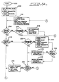
- FIG. 3A therein is shown a first portion of a flow chart representing the logical operation of clutch control in accordance with a preferred embodiment of the present invention.
- operation begins as shown at a start block 200.
- the neutral mode flag is set, the parameter initial condition flag is re-set, and the pressure initial condition flag is re-set as shown generally at a block 202.
- the system determines whether the neutral mode has been requested by the driver at a decision block 204. If so, the parameter initial condition flag is evaluated at a decision block 206. If the parameter initial condition flag has not been set, then it is set at a block 208 in conjunction with setting the engage mode flag.
- the sequence of logic steps generally corresponds to engine start-up.
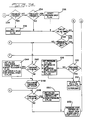
- the system advances to a decision block 210 shown in Figure 3B to determine whether the pressure initial condition flag has been set. This system advances to this point, regardless of whether the parameter initial condition flag has been set. If the pressure initial condition flag has been set, the system advances to the next stage shown generally at a block 212 which outputs the full on duty cycle (0%) to the clutch control valve and then loops back to update the control mode as shown at a block 214. If the pressure initial condition flag has not been set, the system advances from the decision block 210 to a stage shown generally at a block 216. At block 216 the pressure initial condition flag is set, the speed initial condition flag is set, the special start initial condition flag is set, and the touch-off initial condition flag is set. The system then advances to the stage shown at the block 212 and loops back to the update control block shown at 214. Again, as described above, this sequence corresponds generally to engine start-up, although many of the same steps are performed in conjunction with additional operating modes as discussed below.
- the system advances to the next stage shown generally as decision block 218 in which it is determined whether the engage mode flag has been set. This corresponds to the transition from the neutral mode to either the forward or reverse operation modes for the vehicle. As shown at block 214, at least one iteration of the foregoing described neutral mode logic sequence is required upon a forward to reverse or reverse to forward transition.
- the system advances to the next stage shown generally at the decision block 220 in which the parameter initial condition flag is evaluated. If that flag has been set, the system advances to a step shown generally at block 222 in which the engage timer is started, the delay timer is started, the pressure drop flag is re-set, and the parameter initial condition flag is re-set. In accordance with the requirement that at least one neutral mode iteration be performed for each forward/reverse transition, during the first time through the logic steps of the engage mode the parameter initial condition flag will have been set. This ensures the starting of the engage and delay timers, the integrity of the initial pressure drop determination (by resetting the pressure drop flag) as discussed below and the implementation of the correct parameters for forward and reverse.
- the system determines whether the manual shift lever has been placed in reverse as shown at a block 224. If yes, the system advances to a step as shown at block 226 and selects the reverse clutch parameters. If the reverse lever has not been set, this system advances as shown to a step at block 228 and selects the forward clutch parameters. The selected parameters then control clutch operation until there is at least one neutral mode iteration which sets the parameter initial condition flag and the appropriate parameters are againn selected by the branching action of logic block 220. In this fashion, the appropriate clutch control and desired clutch operating characteristics are selected consistent with the improved system layout of Fig. 2.
- the system advances to determine whether the engage timer has timed out as shown at a decision block 230.
- the system also advances directly to block 230 from decision block 220 during subsequent iterations of the engage mode logic because of the resetting actions performed in the initial engage iteration at the block 222.
- the system advances to the next step shown generally at a block 232 at which the engage mode flag is reset and the hold mode flag is set. This represents the end of the engage mode and the beginning of the hold mode. However, if the engage timer has not timed out as determined at the decision block 230, the system advances to a stage for sensing the pressure at the clutch.
- a first evaluation of the clutch pressure is performed as shown generally at a decision block 234 shown in Fig. 3B.
- the preferred embodiment determines whether the pressure is less than a first trigger level. If yes, the selected pressure drop has been sensed and the pressure drop flag is set as shown generally at a block 236. This represents the sensing of the pressure drop of the transducer 108 of Fig. 2 typically associated with a transition from neutral or park and the corresponding opening of the manual valve 102. If the pressure drop flag is set, the system then determines whether the delay timer has timed out as shown at a block 238. If no, the system then advances directly to the decision block 210 and subsequently to the steps shown at block 212 at which the full on duty cycle is output to the clutch control valve to facilitate rapid filling of the clutch actuation chamber.
- the system advances to determine whether the pressure drop flag has been set as shown at a block 240. If yes, the same sequence of events occurs in which the full on duty cycle is output at the block 212. If no, however, this system advances to another stage as shown at a decision block 242. At this stage, the system determines whether the touch off initial condition flag has been set. If yes, then the hold mode pressure set point is initialized, the touch off initial condition flag is re-set, the speed initial condition flag is set, and the special start initial condition flag is set as shown generally at a block 244.
- step 252 an adaptive gain is utilized in accordance with loop equations to output the appropriate duty cycle to maintain the desired pressure in the loop.
- the system also advances to this step shown at 252 if the pressure initial condition flag has not been set.
- the system of the present invention arrives at this point without the pressure initial condition flag being set only subsequent to operation in one of the start modes as described below.
- the system advances to a second pressure sensing step shown generally at a decision block 254 to determine whether the pressure is greater than a second trigger level. If no, then the pressure lies between the first and second trigger points and the system advances to the decision block 238 and the subsequent steps described above. If, however, the pressure is above the second pressure trigger value, as determined at the block 254, the system advances to a step shown generally a block 256 at which the pressure drop flag is reset. This will set in course the sequence of events which typically result in the control of the clutch control valve being passed to the pressure loop controller rather than the full on duty cycle being output. Generally, after the end of the delay timer the system advances from block 238, to block 240 and then to the pressure loop initiating step at block 242. Reiteration of the specific operations associated with these steps is not deemed necessary in view of the foregoing description.
- the system will advance to the subsequent determination of an operating mode as shown in the flow chart portions illustrated in Figures 3C.
- the system determines whether the hold mode has been requested. If yes, the system advances to the decision block 242 and subsequent events as discussed above.
- the system advances to determine whether the special start mode has been requested as shown at a block 260. If yes, the system advances to a second decision block 262 to determine whether the initial conditions for the special start have been set. If yes, then the special start is initialized, the special start initial condition flag is reset, the speed initial condition flag is set, and the touch off initial condition flag is set as shown generally at a block 264. Subsequent to this step, or if the special start initial condition flag had not been set, the system advances to a stage shown generally at a block 266 in which the special start mode algorithm (pressure set point) control is used for the clutch control. The system then advances generally to the logic step shown at decision block 248 and the subsequent events described above.
- the special start mode algorithm pressure set point
- the system determines whether normal start mode has been requested. If yes, at a decision block 270, the system evaluates the speed initial condition flag. If it has been set, the system advances to a step shown generally at block 272 at which the speed loop controller is initialized, the speed initial condition flag is re-set, the special start initial condition flag is set, and the touch off initial condition flag is set. Subsequent to this step, or if the speed initial condition flag was not set, the system advances to a new stage shown generally at a block 274. At this step, the speed loop controller is initiated, the speed loop entered, and the feed forward and the pressure set point control pressure to the clutch. The system then advances to the decision block 248 and subsequent steps as described above.
- decision block 268 if the normal start mode has not been requested, the system defaults to the drive mode as shown generally at a block 276. From this step, the system advances to the decision block 210, and ultimately to the steps shown at block 212 at which the full on-duty cycle is out put to the clutch control valve.
- the foregoing description of the clutch control logic includes references to numerous control modes and to corresponding mode flags.
- the operating modes of the clutch control are the same as the control strategy (discussed previously) modes and are selected by setting the appropriate mode flag.
- the exception is engage mode which is not requested by the control strategy, but is executed automatically in the clutch control logic. Table I below shows the desired mode flag conditions for a preferred embodiment.
- the "Pressure Drop Flag” is used in the engage mode. This flag is set when the pressure drop condition exists. When set, the controller outputs the full-on (0 percent) duty cycle as a result of the logic steps described above.
- a "Feedforward Disable Flag" is used in the special start mode algorithm to either include or disable the throttle feedforward function.
- the engage time should be greater than or equal to the longest time required to stroke the clutch. This may be dependent upon the specific engine used in an application and the corresponding clutch dimensions and performance characteristics.
- the "Delay Timer” becomes effective when entering engage mode to maintain the full-on (0 percent) duty cycle output to the valve until the pressure drop condition is sensed.
- the delay time should be equal to the longest time required to sense the pressure drop, but not longer.
- the "Clutch Pressure Triggers" comprise two triggers that are used in the engage mode to define the pressure drop condition.
- the first trigger senses the pressure drop and should be placed sufficiently low.
- the second trigger terminates the pressure drop and should be close to the touchoff pressure.
- the level of the second trigger should be greater than that of the first trigger.
- a filtered clutch pressure signal may be used desirably to establish the trigger points.
- initial condition flags Five initial condition flags are provided and are used to initialize the various operating modes of the clutch control, as follows:
- the sample rates for the described control system may be any that are found to be acceptable for particular implementations. In a preferred embodiment, the following rates have been found to be acceptable. Pressure loop 5 msec Speed loop 10 msec Feedforward 10 msec Special start 10 msec Set points 20 msec
- the present clutch control logic further includes operation in a special start mode.
- Table VII sets forth special start constants for use in a preferred embodiment.
- REVERSE CLUTCH PARAMETERS: ATCLUR Inverse clutch gain .794 psi/ft-lb 0.725 DINTR Slip speed integrator gain 0.05 psi/rpm/sec .00183 CONSSR Ramp constant 10.0 psi/sec .365 COMMON PARAMETERS: BFFC Feed forward filter frequency 0.25 Hz (Tsamp 0.10) .969
Landscapes
- Engineering & Computer Science (AREA)
- Mechanical Engineering (AREA)
- Transportation (AREA)
- Chemical & Material Sciences (AREA)
- Combustion & Propulsion (AREA)
- General Engineering & Computer Science (AREA)
- Automation & Control Theory (AREA)
- Physics & Mathematics (AREA)
- Fluid Mechanics (AREA)
- Hydraulic Clutches, Magnetic Clutches, Fluid Clutches, And Fluid Joints (AREA)
- Control Of Transmission Device (AREA)
- Control Of Driving Devices And Active Controlling Of Vehicle (AREA)
Claims (17)
- Système de transmission variable en continu comprenant un mode de marche avant et un mode de marche arrière, ledit système comprenant un système de commande d'embrayage destiné à commander un écoulement de fluide sous pression afin de mettre en oeuvre un embrayage (28), caractérisé en ce que le système de commande d'embrayage comprend des moyens de détection de la pression destinés à détecter si la pression dudit fluide de commande est inférieure à une première valeur de déclenchement présélectionnée, et des moyens sensibles auxdits moyens de détection de la pression destinés à procurer un écoulement de fluide à un premier débit audit embrayage (28) lorsque ladite pression détectée est inférieure à ladite première valeur de déclenchement.
- Système selon la revendication 1, comprenant en outre des moyens destinés à détecter ledit mode de fonctionnement, et des moyens destinés à procurer un premier ensemble de paramètres de transfert de fluide pour commander l'écoulement de fluide vers ledit embrayage commandé par fluide (28) en réponse à une détection dudit mode de marche avant et un second ensemble de paramètres de transfert de fluide pour commander un écoulement de fluide vers ledit embrayage commandé par fluide (28) en réponse à une détection dudit mode de marche arrière.
- Système selon la revendication 1 ou la revendication 2, dans lequel lesdits moyens de détection de la pression détectent en outre si ladite pression dudit fluide de commande est supérieure à une seconde valeur de déclenchement présélectionnée si elle n'est pas inférieure à ladite première valeur, et lesdits moyens sensibles auxdits moyens de détection de la pression délivrent du fluide audit embrayage (28) à un second débit lorsque ladite pression est supérieure à ladite seconde valeur de déclenchement.
- Système selon la revendication 3, dans lequel ladite seconde valeur de déclenchement présélectionnée correspond à la pression de seuil d'attaque dudit embrayage (28).
- Système selon l'une quelconque des revendications précédentes, dans lequel ledit premier débit de fluide est un débit maximum de fluide pour le système de commande de l'embrayage.
- Système selon l'une quelconque des revendications précédentes, comprenant en outre des premiers moyens de temporisation pour assurer l'écoulement de fluide audit premier débit jusqu'à ce que lesdits moyens de détection de la pression aient achevé de détecter si la pression dudit fluide de commande est inférieure à la première valeur présélectionnée.
- Système selon la revendication 6, comprenant en outre des seconds moyens de temporisation destinés à mettre en oeuvre lesdits moyens de détection de la pression pendant une durée suffisante pour permettre à la pression au niveau dudit embrayage (28) d'atteindre au moins ladite seconde valeur de pression dans des conditions normales de fonctionnement.
- Système selon l'une quelconque des revendications précédentes, comprenant en outre des moyens pour détecter si ledit mode de marche avant ou ledit mode de marche arrière a été sélectionné, et des moyens sensibles auxdits moyens de détection de mode destinés à procurer une première valeur de déclenchement lorsque ledit mode de marche avant est sélectionné et à fournir une autre première valeur de déclenchement lorsque ledit mode de marche arrière est sélectionné.
- Système selon la revendication 8, comprenant en outre des moyens sensibles auxdits moyens de détection de mode destinés à procurer une seconde valeur de déclenchement lorsque ledit mode de marche avant est sélectionné et une autre seconde valeur de déclenchement lorsque ledit mode de marche arrière est sélectionné.
- Procédé de commande d'une pression de fluide de commande dans un système de commande d'embrayage destiné à un véhicule possédant un système de transmission variable en continu et un embrayage (28) pouvant être mis en oeuvre dans une pluralité de modes de fonctionnement comprenant un mode de marche avant et un mode de marche arrière, dans lequel ledit procédé est caractérisé par les étapes consistant à détecter un passage d'un premier à un second mode sélectionné de fonctionnement du véhicule, à sélectionner un premier ensemble de paramètres d'embrayage afin de commander l'écoulement de fluide vers ledit embrayage (28) lorsque ledit second mode est ledit mode de marche avant, et à sélectionner un second ensemble de paramètres d'embrayage afin de commander l'écoulement de fluide vers l'embrayage (28) lorsque ledit second mode est ledit mode de marche arrière.
- Procédé selon la revendication 10, dans lequel ledit premier mode est un mode de point neutre.
- Procédé selon la revendication 10 ou la revendication 11, comprenant en outre les étapes consistant à détecter si une pression dudit fluide de commande est inférieure à une première valeur de seuil, et à procurer un écoulement de fluide à un premier débit vers ledit embrayage (28) lorsque ladite pression détectée est inférieure à ladite première valeur de seuil.
- Procédé selon la revendication 12, comprenant en outre les étapes consistant à détecter si une pression dudit fluide de commande est supérieure à une seconde valeur de seuil, et à procurer un écoulement de fluide vers ledit embrayage (28) à un second débit lorsque ladite pression est supérieure à ladite seconde valeur de seuil.
- Procédé selon la revendication 13, comprenant en outre l'étape consistant à mettre en oeuvre ladite étape de détection qui détecte si la pression dudit fluide de commande est supérieure à ladite seconde valeur de seuil pendant une durée suffisante pour permettre à la pression dudit fluide de commande d'atteindre ladite seconde valeur de seuil dans des conditions normales de fonctionnement.
- Procédé selon la revendication 13 ou la revendication 14, dans lequel ladite seconde valeur de seuil correspond à une pression de seuil d'attaque dudit embrayage (28).
- Procédé selon l'une quelconque des revendications 12 à 15, dans lequel ledit premier débit de fluide est un débit maximum de fluide pour le système de commande d'embrayage.
- Procédé selon l'une quelconque des revendications 12 à 16, comprenant en outre le fait que la fourniture d'écoulement de fluide audit premier débit de ladite transition est détectée au moins jusqu'à ce que ladite étape de détection qui détecte si une pression est inférieure à une première valeur de seuil soit achevée.
Applications Claiming Priority (2)
| Application Number | Priority Date | Filing Date | Title |
|---|---|---|---|
| US07/402,052 US5007512A (en) | 1989-08-31 | 1989-08-31 | Technique for clutch control in continuously variable transmission systems |
| US402052 | 1989-08-31 |
Publications (3)
| Publication Number | Publication Date |
|---|---|
| EP0415523A2 EP0415523A2 (fr) | 1991-03-06 |
| EP0415523A3 EP0415523A3 (en) | 1991-11-21 |
| EP0415523B1 true EP0415523B1 (fr) | 1995-11-29 |
Family
ID=23590320
Family Applications (1)
| Application Number | Title | Priority Date | Filing Date |
|---|---|---|---|
| EP90307056A Expired - Lifetime EP0415523B1 (fr) | 1989-08-31 | 1990-06-28 | Système de transmission à variation continue avec système de commande d'embrayage |
Country Status (5)
| Country | Link |
|---|---|
| US (1) | US5007512A (fr) |
| EP (1) | EP0415523B1 (fr) |
| JP (1) | JP2948885B2 (fr) |
| CA (1) | CA2019796A1 (fr) |
| DE (1) | DE69023839T2 (fr) |
Families Citing this family (11)
| Publication number | Priority date | Publication date | Assignee | Title |
|---|---|---|---|---|
| US5115395A (en) * | 1987-03-13 | 1992-05-19 | Borg-Warner Automotive, Inc. | Pulse width modulation technique |
| JPH02150554A (ja) * | 1988-11-30 | 1990-06-08 | Suzuki Motor Co Ltd | 連続可変変速機のクリープ制御装置 |
| US5183444A (en) * | 1991-06-28 | 1993-02-02 | Borg-Warner Automotive Inc. | Continuously variable transmission |
| JP3404910B2 (ja) * | 1994-09-14 | 2003-05-12 | 日産自動車株式会社 | 無段変速機の変速ショック軽減装置 |
| DE69611355T2 (de) * | 1995-01-26 | 2001-04-26 | Honda Giken Kogyo K.K., Tokio/Tokyo | Steuergerät für Getriebe |
| DE19858263A1 (de) * | 1998-12-17 | 2000-06-21 | Zahnradfabrik Friedrichshafen | Verfahren zum Überwachen eines stufenlosen Getriebes |
| US6179739B1 (en) | 1998-12-30 | 2001-01-30 | Hamilton Sunstrand Corporation | Continuously variable transmission with control arrangement and method for preventing transmission belt slippage |
| US6290620B1 (en) | 1999-06-25 | 2001-09-18 | Hamilton Sundstrand Corporation | Continuously variable transmission with control arrangement and method for reducing impact of shock load |
| JP3991528B2 (ja) | 1999-10-12 | 2007-10-17 | 日本精工株式会社 | 無段変速機のための発進クラッチ制御装置 |
| US7004296B2 (en) * | 2002-11-27 | 2006-02-28 | Zf Sachs Ag | Torque transmission system for a vehicle |
| US10948081B2 (en) * | 2017-03-02 | 2021-03-16 | Toyota Motor Engineering & Manufacturing North America, Inc. | Downsized CVT oil pump achieved by slip device |
Family Cites Families (19)
| Publication number | Priority date | Publication date | Assignee | Title |
|---|---|---|---|---|
| FR2385902A1 (fr) * | 1977-03-31 | 1978-10-27 | Renault | Procede de regulation d'un groupe moto-propulseur et dispositif permettant sa mise en oeuvre |
| US4433594A (en) * | 1981-04-24 | 1984-02-28 | Borg-Warner Corporation | Variable pulley transmission |
| US4458318A (en) * | 1981-04-24 | 1984-07-03 | Borg-Warner Corporation | Control arrangement for a variable pulley transmission |
| JPS58200855A (ja) * | 1982-05-20 | 1983-11-22 | Nissan Motor Co Ltd | Vベルト式無段変速機の変速制御方法 |
| US4583627A (en) * | 1982-10-22 | 1986-04-22 | Nissan Motor Co., Ltd. | Vehicle/engine operational parameter responsive clutch control |
| US4542665A (en) * | 1982-10-22 | 1985-09-24 | Nissan Motor Co., Ltd. | Control system for continuously variable transmission with space saving automatic clutch control |
| JPS6081560A (ja) * | 1983-10-11 | 1985-05-09 | Nissan Motor Co Ltd | 無段変速機の制御装置 |
| US4665773A (en) * | 1984-03-13 | 1987-05-19 | Mitsubishi Jidosha Kogyo Kabushiki Kaisha | Continuously variable transmission apparatus for automobile |
| JPS60176925U (ja) * | 1984-05-07 | 1985-11-25 | 日産自動車株式会社 | 自動クラツチの制御装置 |
| JPS60260753A (ja) * | 1984-06-06 | 1985-12-23 | Toyota Motor Corp | 車両用無段変速機の制御装置 |
| US4663714A (en) * | 1984-10-18 | 1987-05-05 | J. I. Case Company | Synchronized mid-mounted clutch for variable power train |
| US4718308A (en) * | 1985-03-29 | 1988-01-12 | Borg-Warner Automotive, Inc. | Hydraulic control system for continuously variable transmission |
| US4648496A (en) * | 1985-04-12 | 1987-03-10 | Borg-Warner Automotive, Inc. | Clutch control system for a continuously variable transmission |
| JPH0780425B2 (ja) * | 1986-03-31 | 1995-08-30 | 富士重工業株式会社 | 車両用自動クラツチの制御装置 |
| JPH0689796B2 (ja) * | 1986-04-30 | 1994-11-14 | 富士重工業株式会社 | 車両用自動クラツチの制御装置 |
| US4827805A (en) * | 1987-01-08 | 1989-05-09 | Ford Motor Company | Forward and reverse clutch actuation system for a belt-driven continually variable transmission |
| US4793454A (en) * | 1987-03-13 | 1988-12-27 | Borg-Warner Automotive, Inc. | Continuously variable transmission clutch control system |
| US4811225A (en) * | 1987-03-13 | 1989-03-07 | Borg-Warner Automotive, Inc. | Ratio control technique for continuously variable transmission |
| JPH0676026B2 (ja) * | 1987-08-10 | 1994-09-28 | スズキ株式会社 | 連続可変変速機のクラッチ圧制御方法 |
-
1989
- 1989-08-31 US US07/402,052 patent/US5007512A/en not_active Expired - Lifetime
-
1990
- 1990-06-26 CA CA002019796A patent/CA2019796A1/fr not_active Abandoned
- 1990-06-28 EP EP90307056A patent/EP0415523B1/fr not_active Expired - Lifetime
- 1990-06-28 DE DE69023839T patent/DE69023839T2/de not_active Expired - Fee Related
- 1990-08-31 JP JP2232318A patent/JP2948885B2/ja not_active Expired - Fee Related
Also Published As
| Publication number | Publication date |
|---|---|
| CA2019796A1 (fr) | 1991-02-28 |
| DE69023839T2 (de) | 1996-04-18 |
| JP2948885B2 (ja) | 1999-09-13 |
| EP0415523A2 (fr) | 1991-03-06 |
| JPH03223530A (ja) | 1991-10-02 |
| DE69023839D1 (de) | 1996-01-11 |
| EP0415523A3 (en) | 1991-11-21 |
| US5007512A (en) | 1991-04-16 |
Similar Documents
| Publication | Publication Date | Title |
|---|---|---|
| US5393274A (en) | Touch point identification algorithm for automatic clutch controller | |
| US5168778A (en) | CVT downshift control strategy to minimize slip at the drive pulley | |
| EP0310277B1 (fr) | Détection et compensation du glissement en régime stationnaire pour une transmission de véhicule à moteur | |
| EP0281849B1 (fr) | Système de commande d'embrayage pour une transmission à variation continue | |
| US4706522A (en) | Step-out clutch-to-clutch upshift control | |
| US5272630A (en) | Automatic transmission control and strategy for neutral idle | |
| EP0310276B1 (fr) | Contrôle diagnostique du capteur de vitesse de sortie pour une transmission de véhicule à moteur | |
| US5107723A (en) | Select shock attenuation arrangement for an automatic automotive transmission | |
| US5206805A (en) | Continuously variable transmission clutch control system including special start mode operation | |
| EP0231647A2 (fr) | Système de commande du rapport de transmission pour une transmission variable continue | |
| US5007512A (en) | Technique for clutch control in continuously variable transmission systems | |
| EP0214821A1 (fr) | Système pour régler la pression d'huile pour transmission continue | |
| EP0276022B2 (fr) | Système de commande pour l'embrayage d'un véhicule | |
| US5924955A (en) | Continuously variable transmission controller | |
| EP1406032B1 (fr) | Dispositif de commande de pression hydraulique pour transmission continûment variable | |
| EP0289466B1 (fr) | Transmission à accouplements hydrauliques commandés électroniquement pour tracteurs agricoles et véhicules similaires | |
| US4825991A (en) | Control system for a clutch for a vehicle | |
| GB2286641A (en) | Controlling gear change by controlling clutch fill pressure and shift pressure independently and according to engine speed | |
| US4827804A (en) | System for controlling the pressure of oil in a system for a continuously variable transmission | |
| JP2003074691A (ja) | 自動変速機の制御装置 | |
| JP2977015B2 (ja) | 車両用油圧作動式変速機の油圧制御装置 | |
| EP0283787B1 (fr) | Technique de démarrage particulière pour la commande d'embrayage d'une transmission variable sans palier | |
| US4848528A (en) | Control system for an electromagnetic clutch for a vehicle | |
| EP0281944B1 (fr) | Technique de modulation par largeur d'impulsion pour une soupape de réglage d'une transmission à variateur | |
| JPH0615900B2 (ja) | 自動変速機のライン圧制御装置 |
Legal Events
| Date | Code | Title | Description |
|---|---|---|---|
| PUAI | Public reference made under article 153(3) epc to a published international application that has entered the european phase |
Free format text: ORIGINAL CODE: 0009012 |
|
| AK | Designated contracting states |
Kind code of ref document: A2 Designated state(s): DE FR IT |
|
| PUAL | Search report despatched |
Free format text: ORIGINAL CODE: 0009013 |
|
| AK | Designated contracting states |
Kind code of ref document: A3 Designated state(s): DE FR IT |
|
| 17P | Request for examination filed |
Effective date: 19920325 |
|
| 17Q | First examination report despatched |
Effective date: 19930902 |
|
| GRAA | (expected) grant |
Free format text: ORIGINAL CODE: 0009210 |
|
| AK | Designated contracting states |
Kind code of ref document: B1 Designated state(s): DE FR IT |
|
| PG25 | Lapsed in a contracting state [announced via postgrant information from national office to epo] |
Ref country code: IT Free format text: LAPSE BECAUSE OF FAILURE TO SUBMIT A TRANSLATION OF THE DESCRIPTION OR TO PAY THE FEE WITHIN THE PRE;WARNING: LAPSES OF ITALIAN PATENTS WITH EFFECTIVE DATE BEFORE 2007 MAY HAVE OCCURRED AT ANY TIME BEFORE 2007. THE CORRECT EFFECTIVE DATE MAY BE DIFFERENT FROM THE ONE RECORDED.SCRIBED TIME-LIMIT Effective date: 19951129 |
|
| REF | Corresponds to: |
Ref document number: 69023839 Country of ref document: DE Date of ref document: 19960111 |
|
| ET | Fr: translation filed | ||
| PLBE | No opposition filed within time limit |
Free format text: ORIGINAL CODE: 0009261 |
|
| STAA | Information on the status of an ep patent application or granted ep patent |
Free format text: STATUS: NO OPPOSITION FILED WITHIN TIME LIMIT |
|
| 26N | No opposition filed | ||
| PGFP | Annual fee paid to national office [announced via postgrant information from national office to epo] |
Ref country code: FR Payment date: 20040602 Year of fee payment: 15 |
|
| PGFP | Annual fee paid to national office [announced via postgrant information from national office to epo] |
Ref country code: DE Payment date: 20040630 Year of fee payment: 15 |
|
| PG25 | Lapsed in a contracting state [announced via postgrant information from national office to epo] |
Ref country code: DE Free format text: LAPSE BECAUSE OF NON-PAYMENT OF DUE FEES Effective date: 20060103 |
|
| PG25 | Lapsed in a contracting state [announced via postgrant information from national office to epo] |
Ref country code: FR Free format text: LAPSE BECAUSE OF NON-PAYMENT OF DUE FEES Effective date: 20060228 |
|
| REG | Reference to a national code |
Ref country code: FR Ref legal event code: ST Effective date: 20060228 |