EP0282158A2 - Kommunikationssystem - Google Patents
Kommunikationssystem Download PDFInfo
- Publication number
- EP0282158A2 EP0282158A2 EP88300894A EP88300894A EP0282158A2 EP 0282158 A2 EP0282158 A2 EP 0282158A2 EP 88300894 A EP88300894 A EP 88300894A EP 88300894 A EP88300894 A EP 88300894A EP 0282158 A2 EP0282158 A2 EP 0282158A2
- Authority
- EP
- European Patent Office
- Prior art keywords
- communication
- line
- call
- communication apparatus
- terminal
- Prior art date
- Legal status (The legal status is an assumption and is not a legal conclusion. Google has not performed a legal analysis and makes no representation as to the accuracy of the status listed.)
- Granted
Links
Images




Classifications
-
- H—ELECTRICITY
- H04—ELECTRIC COMMUNICATION TECHNIQUE
- H04Q—SELECTING
- H04Q11/00—Selecting arrangements for multiplex systems
- H04Q11/04—Selecting arrangements for multiplex systems for time-division multiplexing
- H04Q11/0428—Integrated services digital network, i.e. systems for transmission of different types of digitised signals, e.g. speech, data, telecentral, television signals
- H04Q11/0435—Details
- H04Q11/0471—Terminal access circuits
-
- H—ELECTRICITY
- H04—ELECTRIC COMMUNICATION TECHNIQUE
- H04M—TELEPHONIC COMMUNICATION
- H04M1/00—Substation equipment, e.g. for use by subscribers
- H04M1/71—Substation extension arrangements
- H04M1/715—Substation extension arrangements using two or more extensions per line
-
- H—ELECTRICITY
- H04—ELECTRIC COMMUNICATION TECHNIQUE
- H04Q—SELECTING
- H04Q11/00—Selecting arrangements for multiplex systems
- H04Q11/04—Selecting arrangements for multiplex systems for time-division multiplexing
- H04Q11/0428—Integrated services digital network, i.e. systems for transmission of different types of digitised signals, e.g. speech, data, telecentral, television signals
-
- H—ELECTRICITY
- H04—ELECTRIC COMMUNICATION TECHNIQUE
- H04Q—SELECTING
- H04Q2213/00—Indexing scheme relating to selecting arrangements in general and for multiplex systems
- H04Q2213/097—Numbering
-
- H—ELECTRICITY
- H04—ELECTRIC COMMUNICATION TECHNIQUE
- H04Q—SELECTING
- H04Q2213/00—Indexing scheme relating to selecting arrangements in general and for multiplex systems
- H04Q2213/13096—Digital apparatus individually associated with a subscriber line, digital line circuits
-
- H—ELECTRICITY
- H04—ELECTRIC COMMUNICATION TECHNIQUE
- H04Q—SELECTING
- H04Q2213/00—Indexing scheme relating to selecting arrangements in general and for multiplex systems
- H04Q2213/13097—Numbering, addressing
-
- H—ELECTRICITY
- H04—ELECTRIC COMMUNICATION TECHNIQUE
- H04Q—SELECTING
- H04Q2213/00—Indexing scheme relating to selecting arrangements in general and for multiplex systems
- H04Q2213/13209—ISDN
-
- H—ELECTRICITY
- H04—ELECTRIC COMMUNICATION TECHNIQUE
- H04Q—SELECTING
- H04Q2213/00—Indexing scheme relating to selecting arrangements in general and for multiplex systems
- H04Q2213/13299—Bus
-
- H—ELECTRICITY
- H04—ELECTRIC COMMUNICATION TECHNIQUE
- H04Q—SELECTING
- H04Q2213/00—Indexing scheme relating to selecting arrangements in general and for multiplex systems
- H04Q2213/173—Busy signal
-
- H—ELECTRICITY
- H04—ELECTRIC COMMUNICATION TECHNIQUE
- H04Q—SELECTING
- H04Q2213/00—Indexing scheme relating to selecting arrangements in general and for multiplex systems
- H04Q2213/18—Ringing
-
- H—ELECTRICITY
- H04—ELECTRIC COMMUNICATION TECHNIQUE
- H04Q—SELECTING
- H04Q2213/00—Indexing scheme relating to selecting arrangements in general and for multiplex systems
- H04Q2213/204—ISDN protocol; ISO 7
Definitions
- the present invention relates to a communication apparatus used in a communication system having a plurality of communication terminals connected to at least one line.
- an ISDN integrated services digital network
- Up to eight terminals can be connected to the ISDN line.
- the ISDN line has three communication channels, that is, two data channels (B channels) and one control channel (D channel) and up to eight channels are connected to the line.
- B channels data channels
- D channel control channel
- the communication channel When the communication channel is not busy, it can communicate in response to a communication request from a terminal.
- a common address which is common to all terminals and sub-addresses given to respective terminals are used.
- terminals When terminals are to be called, if only the common address is designated, all terminals are called and one of them is connected. If a sub-address is designated in addition to the common address, only the terminal of the designated address is called.
- a terminal may not communicate if the line is busy. Whether it can communicate or not is not known until it issues a communication request.
- the terminal In the ISDN system, if the terminal is designated by the sub-address, only the designated terminal is called. If the terminal corresponding to the sub-address is busy or no such terminal exists, an operator who tries to connect to the line must again designate the common address and recall.
- ISDN integrated services digital network
- Fig. 1 shows a system configuration of the ISDN network.
- numeral 202 denotes a switcher in the ISDN network.
- Numeral 201 denotes a network terminator (NT) which communicates data with the switcher 202.
- Numerals 203 - 206 denote terminals connected to the NT 201.
- the ISDN network has two B channels as data channels and one D channel as a control channel.
- the NT 201 has an address assigned thereto, and the terminals 203 - 206 have respective sub-addresses assigned thereto.
- the switcher 202 When data is to be received, the switcher 202 responds to address information designated by the transmission requesting station to call the NT 201 through the D channel. If the address is designated by the requesting station, the NT 201 calls the designated sub-address terminal on the condition that it is not busy. If the sub-address is not designated by the requesting station, the NT 201 calls all non-busy terminals and connects a non-busy channel to the terminal which has first responded.
- the NT 201 When data is to be transmitted, if the terminal designates an address of the destination station through the D channel, the NT 201 sends address information through the D channel if there is a non-busy channel, to call the destination station.
- the terminals connectable to the ISDN include digital telephone set, facsimile machine, telex and other communication terminals.
- a called sub-address is displayed.
- Fig. 2 shows an external view of a digital telephone set of the first embodiment.
- Numeral 21 denotes a digital telephone set body
- numeral 22 denotes a handset
- numeral 23 denotes key buttons for inputting a telephone number
- numeral 24 denotes lamps for indicating a called sub-address.
- Fig. 3 shows a block diagram of the digital telephone set of the first embodiment.
- the present embodiment comprises a digital telephone set body 31 and a handset 40 which is a communication transmitter/receiver.
- the digital telephone set body 31 comprises a CPU 32, a ROM 33, a RAM 34, a communication channel 37, an I/O controller 35, a codec 36 for analog-digital conversion, a key pod 38 and a lamp/button 39.
- the CPU 32 controls the digital telephone set body 31.
- the ROM 33 contains a control program according to a flow chart shown in Fig. 5, and the RAM 34 stores communication data.
- Fig. 4 shows a signal sequence of the digital telephone set in the ISDN network.
- numeral 51 denotes a call request command (SETUP)
- numeral 52 denotes a calling command (ALERT)
- numeral 53 denotes a respond command (CONN)
- numeral 54 denotes a connection completion command (CONN ACK)
- numeral 55 denotes speech data (B-CH signal)
- numeral 56 denotes a disconnection command (DISC)
- numeral 57 denotes a recovery request command (REL)
- numeral 58 denotes a recovery confirmation command (REL COM).
- Fig. 5 shows a flow chart of the control operation of the CPU 32 of the first embodiment.
- the setup command (SETUP) 51 of Fig. 4 is sent to all terminals connected to the bus, through the bus line S of Fig. 1.
- the SETUP command 51 includes a sub-address and information on type of service of the call.
- a step S1 of Fig. 5 if the terminal receives the SETUP command 51, it checks in a step S2 whether the sub-address contained in the SETUP command 51 as a parameter is equal to the sub-address of its own. If they are equal, it sends a calling signal (52 in Fig.
- step S4 in a step S3, and rings a calling bell in a step S4 to inform to an operator of the call.
- step S5 the operator's response is confirmed. If the operator's response is confirmed, the acknowledge command (53 in Fig. 4) is sent in a step S6.
- the connection completion command 54 is received, speech is started in a step S7 (55 in Fig. 4).
- step S8 end of operator's speech is confirmed.
- step S9 the disconnection command (56 in Fig. 4) is sent and the recovery request command (57 in Fig. 4) is received and the recovery confirmation command (REL COM 58 in Fig. 4) is sent.
- the terminal becomes idle in a step S10 and the communucation terminates.
- step S2 if the sub-address contained in the SETUP command 51 as the parameter is not equal to the sub-address owned by the terminal, the lamp 24 in Fig. 2 of the corresponding sub-address is turned on in a step S11.
- a calling sound to indicate the call to other terminal is generated to inform it to the operator.
- step S13 whether the other terminal has responded to the call or not is checked, and in a step S14, whether the line has been disconnected or not is checked. If the decision in the step S13 or S14 is YES, the sub-address indication lamp is turned off in a step S14A and the calling tone for the other terminal is stopped in a step S15. Thus, the terminal becomes idle in the step S10.
- the steps S11 et seq. of Fig. 5 are carried out.
- the steps S11 et seq. may be carried out only when the type of service contained in the parameter of the SETUP command 51 and the type of service owned by the terminal are equal and other call may be ignored.
- the call of the sub-address of other terminal is indicated by the lamp, although it may be displayed by characters by using a LCD.
- the signal sequence may be different than that shown in Fig. 4 so long as the called terminal is designated by the sub-address.
- the digital telephone set of the ISDN network receives a call to other terminal connected thereto through the bus, the called sub-address is indicated by the lamp so that the operator of that terminal can know the call to the other terminal.
- a second embodiment in which a call to other communication apparatus is altered to the one to its own apparatus is explained.
- the configuration of the second embodiment is similar to that of the first embodiment shown in Figs. 2 to 4 but a control operation is different.
- Fig. 6 shows a flow chart of a control operation of the CPU 32 of the digital telephone set of the second embodiment. The second embodiment is now explained with reference to the flow chart of Fig. 6.
- the SETUP command 51 of Fig. 4 is sent to all terminals connected to the bus through the bus line S of Fig. 1.
- the SETUP command 51 includes a sub-address and information on the type of service of the call. This is similar to the first embodiment.
- a step S101 of Fig. 6 when the terminal receives the SETUP command, the sub-address contained in the SETUP command as the parameter is compared with the sub-address owned by the terminal in a step S102. If they are equal, a calling signal (52 in Fig. 4) is sent in a step S103 and a calling sound (bell) is generated in a step S104 to inform to the operator of the call.
- a step S105 whether the line has been disconnected by the calling station or not is checked.
- a step S106 whether other terminal has responded on behalf of its own terminal or not is checked.
- a step S107 whether the operator has hooked off the handset or not is checked. If the decision in the step S105 or S106 is YES, the terminal becomes idle in a step S114. If the off-hook by the operator is detected in the step S107, the calling sound is stopped in a step S108 and the acknowledge command 53 of Fig. 4 is sent to the network in a step S109. When the connection completion command 54 of Fig. 4 is received, the speech mode is started in a step S110 (55 in Fig. 4).
- the disconnection command (56 in Fig. 4) is sent in a step S112 and the recovery request command 57 of Fig. 4 is received. Then, the recovery confirmation command 58 of Fig. 4 is sent and the line is disconnected, and the terminal becomes idle in the step S114.
- step S102 if the sub-address contained in the SETUP command 51 as the parameter is "3", for example, and the sub-address owned by the terminal is "1", it is determined in the sub-address check that the call is not to its own terminal.
- the calling signal 52 of Fig. 4 is sent.
- step S116 the lamp 24 of Fig. 2 corresponding to the sub-address 3 is turned on.
- step S117 the call to other terminal is informed. It may be informed to the operator of its own terminal by generating the calling sound.
- a step S118 whether the operator has depressed the sub-address button 24 (which also functions as the sub-address indication lamp) of Fig. 2 to respond to the call on behalf of the other terminal is checked.
- a step S119 whether the line has been disconnected by the network or not is checked.
- a step S120 whether other terminal has responded or not is checked. If the decision in the step S119 or S120 is YES, the sub-address indication lamp is turned off in a step S121, the calling tone to the other terminal is stopped in a step S122, and the terminal becomes idle in the step S114.
- step S118 if it is detected that the operator has depressed the sub-address button to respond on behalf of the other terminal, the sub-address button is turned off in a step S123, and the calling tone to the other terminal is stopped in a step S124.
- a step S125 the off-hook by the operator is checked. If the off-hook is detected, the response command 53 of Fig. 4 is sent to the network in a step S126.
- the connection completion command 54 of Fig. 4 is received, the speech mode is started in a step S127 (55 in Fig. 4).
- the disconnection command 56 in Fig. 4
- the recovery request command 27 of Fig. 4 is received.
- the recovery confirmation command 28 of Fig. 4 is sent and the line is disconnected, and the terminal becomes idle in the step S114.
- the steps S115 et seq. of Fig. 6 are carried out.
- the steps S115 et seq. of Fig. 6 may be carried out only when the type of service owned by its own terminal and the type of service contained in the SETUP command 51 are equal, and other call may be ignored.
- the steps S105 - S107 and S118 - S120 of Fig. 6 if there is another call, it may be parallelly processed from the step S101 so that more than one calls are parallelly processed.
- the signal sequence may be different than that shown in Fig. 4 so long as the called terminal is designated by the sub-address.
- the digital telephone set for the ISDN network is provided with the function of dynamically altering the sub-address owned by its own terminal in response to the operator's instruction, the call to any ISDN terminal connected with its own terminal through the bus can be responded by its own terminal.
- Fig. 7 shows a configuration of a telephone set having a line monitor function of the third embodiment.
- a hook switch 302 When a user hooks off a handset 301, a hook switch 302 is turned on and it is informed to a control unit 304 through an I/O port 303.
- the control unit 304 starts a preparatory operation for calling. It converts a calling request command to a D channel transmission signal and sends it to a framing circuit 310, which frames it into a 2B + D channel basic access signal, which is sent to the NT 201 of Fig. 1 through an interface circuit 311.
- the NT 201 examines the usage status of the equipments connected to the NT 201, and if there is no trouble, it informs it through the D channel and a receive line .
- the control unit 304 informs this information to a voice synthesis circuit 305 as a command and switches an analog switch 306 to select to voice synthesis circuit 305, through the I/O port 303.
- the voice synthesis circuit 305 generates a first sound signal which is sent to a speaker 308 through an adder 307.
- the first sound signal may be a 400 Hz continuous sound so that there is no feeling of difference compared to a conventional domestic analog telephone set.
- the voice synthesis circuit 305 If the B channel is busy because other equipment than the telephone set under consideration uses the line, it is informed to the control unit 304 by the NT 201 through the same route as that explained above. In this case, the voice synthesis circuit 305 generates a voice message signal indicating that the line is busy with other equipment, and it is supplied to the speaker 308.
- the input dial number is sent to the control unit 304 through the I/O port 303.
- the control unit 304 converts the number to a D channel transmission signal, which is sent to the NT 201 through the framing circuit 310, the interface circuit 311 and a transmission line .
- the control unit 304 sends a command to the voice synthesis circuit 305 to cause it to generate a pseudo-calling signal, which is supplied to the speaker 308 so that the user waits for the connection.
- the dial number of the partner is wrong or the line of the partner is busy with other equipment than the telephone set, it is informed to the control unit 304 by the NT 201 of Fig. 1 so that the information is informed to the user as a voice message to request to the user to hook on the handset 301.
- the speech mode is started.
- the voice signal inputted from a microphone 313 of the handset 301 is supplied to an encoder 317 of a PCM codec 315 where it is PCM-coded.
- it is converted to a B channel transmission signal, which is supplied to the framing circuit 310.
- the framing circuit 310 converts the B channel signal to the 2B + D channel basic access unit, which is sent to the NT 201 through the interface circuit 311.
- a side tone circuit 314 and the adder 307 are provided to impart natural feeling in the speech. They return a portion of sound generated by the user to generate a side tone.
- the speech signal of the partner is converted to a B channel receive signal by a deframing circuit 312. It is a PCM code which is converted to an analog voice signal by a decoding circuit 316 of the PCM codec 315.
- the analog switch 306 is switched to select the voice synthesis circuit 315 under the control of the control unit 304 so that the decoded voice signal is supplied to the speaker 308 through the adder 307.
- the control unit 304 determines whether the call is to the telephone set or not, and if it is, it causes the bell 306 to ring through the I/O circuit 303.
- the telephone set does not respond to it.
- the hook switch 302 is turned on and it is informed to the control unit 304 through the I/O circuit 303.
- the control unit 304 detects the response by the user, it informs to the framing circuit 310 through the D channel transmission signal that the telephone set enters into the speech mode. This information is informed to the NT 201 through the interface circuit 311.
- the control unit 304 switch the analog switch 306 to select the PCM codec 315, through the I/O circuit 303. Thus, the speech mode is ready.
- the first sound signal and the calling signal are generated by the voice synthesis circuit.
- those signals may be voice messages.
- various information for example, line status
- various information supplied by the NT 201 through the D channel are supplied to the user in the form of voice message which is very easy to understand. Accordingly, the operability of the telephone set is considerably improved.
- Fig. 8 shows an external view of a digital telephone set of the fourth embodiment
- Fig. 9 shows a block diagram of a configuration of the digital telephone set.
- the difference in Fig. 8 from Fig. 2 is that the sub-address indication lamp (sub-address button) 24 is not provided.
- the difference in Fig. 9 from Fig. 3 is that the lamp/button 39 is not provided.
- the function of the fourth embodiment to be described later may be provided to the telephone set of the first embodiment shown in Figs. 2 and 3.
- Fig. 10 shows a flow chart of a control operation of the CPU 32 of the fourth embodiment.
- the fourth embodiment is now explained with reference to the flow chart of Fig. 10.
- step S401 of Fig. 10 the operator registers from the terminal a notice for B channel availability in a step S402.
- "99" is dialed to register the notice for B channel availability.
- the apparatus which has been registered by the operator for the notice for B channel availability monitors the D channel signal sequence in a step S403 to check if the B1 channel is available.
- step S404 it checks if the B2 channel is available. If the availability of the B channel is detected in the step S403 or S404, the ringing bell is rung in a step S405 to call the operator of the calling station.
- a step S406 the response by the calling station operator by his/her hooking off the handset is checked. If the response by the operator is detected in the step S406, a dial tone is generated in a step S407 to inform to the operator that he/she is permitted to call. Thus, the operator calls. In a step S408, normal speech mode is started.
- the apparatus may automatically recall when the B channel becomes available, and the connection with the called station may be informed to the operator of the calling station.
- the apparatus monitors the use status of the B channels by the request of the operator and if the B channel becomes available, it is informed to the operator. Accordingly, the work of the operator is reduced and the efficiency of line is improved.
- the configuration of the digital telephone set of the fifth embodiment is some as that of Figs. 8 and 9 or Figs. 2 and 3.
- Fig. 11 shows a signal sequence of the fifth embodiment
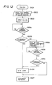
- Fig. 12 shows a flow chart of a control operation of the CPU 32 of the digital telephone set of the fifth embodiment.
- the fifth embodiment is explained with reference to Figs. 11 and 12.
- numeral 41 denotes a call request command (SET UP)
- numeral 42 denotes a call negate command (CONN NEG)
- numeral 43 denotes a calling command (ALERT)
- numeral 44 denotes a response command (CONN)
- numeral 45 denotes a connection completion command (CONN ACK)
- numeral 46 denotes speech data (B-CH signal)
- numeral 47 denotes a disconnection command (DISC)
- numeral 48 denotes a recovery request command (REL)
- numeral 49 denotes a recovery confirmation command (REL COM).
- step S501 of Fig. 12 the operator inputs to the terminal a dial number of the called station with a sub-address in a step S502.
- step S503 the terminal which received the dial number of the called station starts the calling operation. It sends the SET UP command 41 of Fig. 11 to the ISDN network.
- step S504 the calling terminal waits for the reception of the CONN commands 44 and 42 of Fig. 11. When it receives the CONN command, it checks if the command is affirmative command or negative command in step S505.
- the calling terminal sends the CONN ACK command 45 of Fig. 11, and the speech mode is started in a step S506 (46 in Fig. 11).
- the speech terminates in a step S507 and the calling terminal receives the DISC command 47 of Fig. 11, it sends the REL command 48 and then receives the REL COM command 49.
- the disconnection of the network is confirmed and the communication is terminated.
- step S505 if the negative command is received, there may be no corresponding terminal at the transmitted sub-address.
- the calling terminal automatically deletes the sub-address from the dial number of the called station input in the step S502 and send the dial number without sub-address. Then, the calling terminal waits for the reception of the CONN command in the step S509.
- the CONN command When it receives the CONN command, it checks in a step S510 whether the command is an affirmative command or a negative command. If it is the affirmative command, the speech is started in the step S506 and the network is disconnected in the step S507.
- the network is disconnected in the step S507 to terminate the communication.
- the dial number with the sub-address is sent, and if there is no corresponding terminal in the called station, the sub-address is deleted and the recall is made.
- the recall is made when the negative CONN command is received.
- a negation reason code contained in the negative CONN command may be analyzed so that the recall is made only when the connection is permitted if the dial number is not accompanied with the sub-address.
- the calling terminal when the calling terminal calls by the dial number with the sub-address and cannot success the connection, the calling terminal automatically changes it to the dial number without the sub-address and recalls. Accordingly, even if the sub-address of the called terminal has been changed, the connection is made to the called terminal without the intervention of the calling station operator.
- Fig. 13 shows an external view of a digital telephone set of the sixth embodiment.
- Numeral 21 denotes a digital telephone set body
- numeral 22 denotes a handset
- numeral 23 denotes key buttons for inputting a telephone number
- numeral 24 ⁇ denotes lamps for indicating a busy B channel.
- Fig. 14 shows a block diagram of the present embodiment.
- the present embodiment comprises a digital telephone set body 31 and a handset 40 which is a speech transmitter/receiver.
- the digital telephone set body 31 comprises a CPU 32, a ROM 33, a RAM 34, a communication chip 37, an I/O controller 35, a codec 36 for analog/digital conversion, a key pad 38 and a lamp 39 ⁇ .
- the CPU 32 controls the digital telephone set body 31, the ROM 33 contains a control program in accordance with a flow chart of Fig. 16, and the RAM 34 stores communication data.
- Fig. 15 shows a signal sequence of the digital telephone in the ISDN network.
- numeral 51 denotes a call request command (SET UP)
- numeral 52 denotes a calling command (ALERT)
- numeral 53 denotes a response command (CONN)
- numeral 54 denotes a connection completion command (CONN ACK)
- numeral 55 denotes speech data (B-CH signal)
- numeral 56 denotes a disconnection command (DISC)
- numeral 57 denotes a recovery request command (REL)
- numeral 58 denotes a recovery confirmation command (REL COM).
- Fig. 15 is identical to Fig. 4.
- Fig. 16 shows a flow chart of the operation of the embodiment.
- a step S601 whether the terminal connected to the same subscriber line to that of its own terminal has called by the SETUP command 51 of Fig. 15 or has been disconnected by the REL COM command 58 of Fig. 15 is checked.
- step S602. If the call has been made, whether the call uses the B channel or not is checked by the signal sequence in a step S602. If it does not use the B channel, the terminal becomes idle in a step S608.
- the particular B channel to be used is determined in a step S603. If only the B1 channel is to be used, the B1 channel lamp 24 ⁇ of Fig. 13 is turned on in a step S604.
- the B2 channel lamp 24 ⁇ of Fig. 13 is turned on in a step S605. If both the B1 and B2 channels are to be used in the step S603, the B1 channel lamp 24 ⁇ of Fig. 13 is turned on in a step S606 and the B2 channel lamp 24 ⁇ of Fig. 13 is turned on in a step S607.
- the digital telephone set of the present embodiment becomes idle in a step S608.
- step S601 If the disconnection is detected in the step S601, whether the call has used the B channel or not is determined in a step S609. If it has not used the B channel, the telephone set becomes idle in the step S608. If it has used the B channel, the particular B channel used is determined in a step S610. If only the B1 channel has been used, the B1 channel lamp 24 ⁇ of Fig. 13 is turned off in a step S611. If only the B2 channel has been used in the step S610, the B2 channel lamp 24 ⁇ of Fig. 13 is turned off in a step S612. If both the B1 and B2 channels have been used in the step S610, the B1 channel lamp is turned off in a step S613 and the B2 channel lamp is turned off in a step S614.
- the digital telephone set becomes idle in the step S608.
- the busy B channel is indicated by the lamp.
- it may be displayed by characters by using an LCD.
- the digital telephone set for the ISDN network is provided with the function to indicate the use status of the B channel to which the telephone set is connected, by the lamps. Accordingly, the operator, when he/she calls, can readily check whether the line is available or not.
- the ISDN network is used although the present invention is not limited to the ISDN but is applicable to any conventional public line (telephone line or digital line) to which a plurality of communication apparatus are connected.
- the digital telephone set is used.
- telephone sets, facsimile machines, teletexes, telexes, personal computers and other communication apparatus may be connected to the ISDN network and the present invention is not limited to the digital telephone set but is applicable to various other communication apparatus.
Landscapes
- Engineering & Computer Science (AREA)
- Computer Networks & Wireless Communication (AREA)
- Signal Processing (AREA)
- Telephonic Communication Services (AREA)
- Data Exchanges In Wide-Area Networks (AREA)
Priority Applications (1)
| Application Number | Priority Date | Filing Date | Title |
|---|---|---|---|
| EP92201232A EP0500194B1 (de) | 1987-02-10 | 1988-02-03 | Kommunikationsgerät |
Applications Claiming Priority (12)
| Application Number | Priority Date | Filing Date | Title |
|---|---|---|---|
| JP62029038A JPH0695711B2 (ja) | 1987-02-10 | 1987-02-10 | 通信端末装置 |
| JP62029034A JPH07101909B2 (ja) | 1987-02-10 | 1987-02-10 | 通信装置 |
| JP29038/87 | 1987-02-10 | ||
| JP29037/87 | 1987-02-10 | ||
| JP29034/87 | 1987-02-10 | ||
| JP62029037A JPH0744617B2 (ja) | 1987-02-10 | 1987-02-10 | 電話端末装置 |
| JP62031191A JPH07110029B2 (ja) | 1987-02-13 | 1987-02-13 | 通信端末装置 |
| JP31191/87 | 1987-02-13 | ||
| JP31192/87 | 1987-02-13 | ||
| JP62031192A JPH0793657B2 (ja) | 1987-02-13 | 1987-02-13 | 通信端末装置 |
| JP62031868A JPS63199552A (ja) | 1987-02-14 | 1987-02-14 | 通信装置 |
| JP31868/87 | 1987-02-14 |
Related Child Applications (2)
| Application Number | Title | Priority Date | Filing Date |
|---|---|---|---|
| EP92201232.3 Division-Into | 1988-02-03 | ||
| EP92201232A Division EP0500194B1 (de) | 1987-02-10 | 1988-02-03 | Kommunikationsgerät |
Publications (3)
| Publication Number | Publication Date |
|---|---|
| EP0282158A2 true EP0282158A2 (de) | 1988-09-14 |
| EP0282158A3 EP0282158A3 (en) | 1989-06-07 |
| EP0282158B1 EP0282158B1 (de) | 1993-06-16 |
Family
ID=27549435
Family Applications (2)
| Application Number | Title | Priority Date | Filing Date |
|---|---|---|---|
| EP92201232A Expired - Lifetime EP0500194B1 (de) | 1987-02-10 | 1988-02-03 | Kommunikationsgerät |
| EP88300894A Expired - Lifetime EP0282158B1 (de) | 1987-02-10 | 1988-02-03 | Kommunikationssystem |
Family Applications Before (1)
| Application Number | Title | Priority Date | Filing Date |
|---|---|---|---|
| EP92201232A Expired - Lifetime EP0500194B1 (de) | 1987-02-10 | 1988-02-03 | Kommunikationsgerät |
Country Status (3)
| Country | Link |
|---|---|
| US (3) | US5583930A (de) |
| EP (2) | EP0500194B1 (de) |
| DE (2) | DE3856195T2 (de) |
Cited By (5)
| Publication number | Priority date | Publication date | Assignee | Title |
|---|---|---|---|---|
| FR2622075A1 (fr) * | 1987-10-19 | 1989-04-21 | Canon Kk | Appareil et systeme de communication, notamment de donnees de son ou d'image |
| EP0371676A3 (de) * | 1988-11-30 | 1992-01-22 | AT&T Corp. | Änderung der Kommikationskanal-Zuweisung |
| EP0371674A3 (de) * | 1988-11-30 | 1992-01-22 | AT&T Corp. | Kommunikationskanalreservierung |
| EP0581033A3 (de) * | 1992-06-30 | 1994-11-17 | Toshiba Kk | Datenübertragungssystem unter Verwendung einer Speicherung mit FIFO-Konfiguration. |
| WO1998025391A1 (en) * | 1996-12-05 | 1998-06-11 | Northern Telecom Limited | Distinctive ringing and distinctive call-waiting tones in an isdn |
Families Citing this family (6)
| Publication number | Priority date | Publication date | Assignee | Title |
|---|---|---|---|---|
| EP0594185B1 (de) * | 1992-10-22 | 2002-01-23 | Hitachi, Ltd. | Kommunikationsanlage |
| CA2148384C (en) * | 1994-06-27 | 2003-03-18 | Charles Clifford Hallock | Methods for performing intelligent network services with an isdn network terminator located at a subscriber's premise |
| US5991387A (en) * | 1997-03-21 | 1999-11-23 | Siemens Information And Communications Network, Inc. | Monitoring and controlling channels to improve the interface of calls |
| SE514331C2 (sv) * | 1997-05-07 | 2001-02-12 | Ericsson Telefon Ab L M | Metod och anordning för att erhålla dynamisk bandbredd genom variabel kanaltilldelning i ISDN |
| US5943409A (en) * | 1997-07-11 | 1999-08-24 | Bellsouth Intellectual Property Corporation | Method and system for providing automatic recall information in a telecommunications network |
| US6078655A (en) * | 1997-08-27 | 2000-06-20 | At&T Corp | Automatic international reattempt method and apparatus |
Family Cites Families (32)
| Publication number | Priority date | Publication date | Assignee | Title |
|---|---|---|---|---|
| US3701855A (en) * | 1971-01-18 | 1972-10-31 | Bell Telephone Labor Inc | First idle line pickup service |
| US3956595A (en) * | 1974-10-03 | 1976-05-11 | Western Electric Company | Circuitry for providing executive ringback in a PBX system |
| US3951248A (en) * | 1974-11-07 | 1976-04-20 | Bell Telephone Laboratories, Incorporated | Telephone line visual status indication circuit |
| US4209668A (en) * | 1978-09-20 | 1980-06-24 | Utility Verification Corp. | Telephone having reiterative dialing feature |
| US4296282A (en) * | 1980-06-30 | 1981-10-20 | Bell Telephone Laboratories, Incorporated | Incoming call identification arrangement |
| IT1144160B (it) * | 1981-03-12 | 1986-10-29 | Cselt Centro Studi Lab Telecom | Sistema di accesso multiplo di terminali su una linea telefonica numerica |
| EP0066668B1 (de) * | 1981-06-04 | 1986-04-09 | Siemens-Albis Aktiengesellschaft | Verfahren zum Betrieb einer Fernsprechanlage |
| GB2106354B (en) * | 1981-09-08 | 1985-02-20 | Standard Telephones Cables Ltd | Alarm monitor |
| US4519072A (en) * | 1982-11-10 | 1985-05-21 | Rockwell International Corporation | Answer supervision system |
| CA1188831A (en) * | 1982-12-14 | 1985-06-11 | Mitel Corporation | Telephone indicator |
| JPS59114954A (ja) * | 1982-12-20 | 1984-07-03 | Nec Corp | 自動キヤンプオン機能を備えた事業所電話交換機 |
| US4626627A (en) * | 1983-10-07 | 1986-12-02 | Teledex | Telephone line selector for use with a PBX |
| US4567324A (en) * | 1983-10-11 | 1986-01-28 | Gte Business Communication Systems, Inc. | Secretarial telephone station for use with a secretarial answering system |
| JPS611153A (ja) * | 1984-05-17 | 1986-01-07 | Fujitsu Ltd | 複数コ−ル同時着信制御方法 |
| GB2165420B (en) * | 1984-10-03 | 1988-06-22 | Stc Plc | Data handling system |
| DE3437540A1 (de) * | 1984-10-12 | 1986-04-24 | Siemens AG, 1000 Berlin und 8000 München | Schaltungsanordnung zur anzeige der teilnehmerleitungsbelegung durch zusatzeinrichtungen an der zugehoerigen digitalen fernsprechstation |
| US4636589A (en) * | 1985-02-04 | 1987-01-13 | American Phone Products | In-line telephone intercom system |
| JP2550937B2 (ja) * | 1985-03-04 | 1996-11-06 | 国際電信電話株式会社 | Isdn加入者系端末制御方式 |
| JPH0640647B2 (ja) * | 1985-08-01 | 1994-05-25 | 国際電信電話株式会社 | Isdn端末間内線通信方式 |
| US4723273A (en) * | 1985-09-25 | 1988-02-02 | American Telephone And Telegraph Company, At&T Bell Laboratories | Discretionary call forwarding |
| US4775975A (en) * | 1985-11-26 | 1988-10-04 | American Telephone And Telegraph Company And At&T Information Systems Inc. | Dial tone detection arrangement with a detection notification feature |
| US4694483A (en) * | 1986-06-02 | 1987-09-15 | Innings Telecom Inc. | Computerized system for routing incoming telephone calls to a plurality of agent positions |
| US4740955A (en) * | 1986-10-29 | 1988-04-26 | Tie/Communications, Inc. | Communications system having voice and digital data capability and employing a plurality of voice and data buses in main service unit and serial packetized transmission to and from telephones |
| JP2696509B2 (ja) * | 1987-05-13 | 1998-01-14 | 株式会社リコー | データ端末装置の制御方式 |
| JPS63283351A (ja) * | 1987-05-15 | 1988-11-21 | Canon Inc | Isdnタ−ミナルアダプタ |
| US4995073A (en) * | 1987-10-10 | 1991-02-19 | Canon Kabushiki Kaisha | Communication apparatus and communication system having automatic attribution switching |
| JPH01158864A (ja) * | 1987-12-16 | 1989-06-21 | Canon Inc | 通信端末装置 |
| JPH01168155A (ja) * | 1987-12-24 | 1989-07-03 | Canon Inc | 通信端末装置 |
| JPH01186939A (ja) * | 1988-01-21 | 1989-07-26 | Fuji Photo Film Co Ltd | ハロゲン化銀カラー写真感光材料の処理方法 |
| US5245651A (en) * | 1988-08-22 | 1993-09-14 | Canon Kabushiki Kaisha | Communication apparatus for storing abandoned call information |
| US5291549A (en) * | 1989-06-07 | 1994-03-01 | Canon Kabushiki Kaisha | Private branch exchange and line exchange method |
| US5280520A (en) * | 1989-06-28 | 1994-01-18 | Canon Kabushiki Kaisha | Apparatus for speed and data communication |
-
1988
- 1988-02-03 EP EP92201232A patent/EP0500194B1/de not_active Expired - Lifetime
- 1988-02-03 DE DE3856195T patent/DE3856195T2/de not_active Expired - Fee Related
- 1988-02-03 DE DE88300894T patent/DE3881724T2/de not_active Expired - Fee Related
- 1988-02-03 EP EP88300894A patent/EP0282158B1/de not_active Expired - Lifetime
-
1995
- 1995-01-05 US US08/369,271 patent/US5583930A/en not_active Expired - Fee Related
- 1995-06-07 US US08/476,346 patent/US5572580A/en not_active Expired - Fee Related
- 1995-06-07 US US08/476,027 patent/US5648971A/en not_active Expired - Fee Related
Cited By (8)
| Publication number | Priority date | Publication date | Assignee | Title |
|---|---|---|---|---|
| US4995073A (en) * | 1987-10-10 | 1991-02-19 | Canon Kabushiki Kaisha | Communication apparatus and communication system having automatic attribution switching |
| FR2622075A1 (fr) * | 1987-10-19 | 1989-04-21 | Canon Kk | Appareil et systeme de communication, notamment de donnees de son ou d'image |
| EP0371676A3 (de) * | 1988-11-30 | 1992-01-22 | AT&T Corp. | Änderung der Kommikationskanal-Zuweisung |
| EP0371674A3 (de) * | 1988-11-30 | 1992-01-22 | AT&T Corp. | Kommunikationskanalreservierung |
| EP0581033A3 (de) * | 1992-06-30 | 1994-11-17 | Toshiba Kk | Datenübertragungssystem unter Verwendung einer Speicherung mit FIFO-Konfiguration. |
| US5608388A (en) * | 1992-06-30 | 1997-03-04 | Kabushiki Kaisha Toshiba | Data transfer system using memory with FIFO structure |
| WO1998025391A1 (en) * | 1996-12-05 | 1998-06-11 | Northern Telecom Limited | Distinctive ringing and distinctive call-waiting tones in an isdn |
| US5953407A (en) * | 1996-12-05 | 1999-09-14 | Nortel Networks Corporation | Distinctive ringing and distinctive call-waiting tones in an ISDN |
Also Published As
| Publication number | Publication date |
|---|---|
| EP0500194B1 (de) | 1998-05-27 |
| EP0282158A3 (en) | 1989-06-07 |
| EP0500194A3 (en) | 1993-04-14 |
| DE3881724T2 (de) | 1993-11-11 |
| DE3856195D1 (de) | 1998-07-02 |
| EP0500194A2 (de) | 1992-08-26 |
| DE3856195T2 (de) | 1998-10-08 |
| US5583930A (en) | 1996-12-10 |
| EP0282158B1 (de) | 1993-06-16 |
| DE3881724D1 (de) | 1993-07-22 |
| US5648971A (en) | 1997-07-15 |
| US5572580A (en) | 1996-11-05 |
Similar Documents
| Publication | Publication Date | Title |
|---|---|---|
| US5857017A (en) | Call waiting notifying apparatus | |
| US5648971A (en) | Communication apparatus providing improved information on the states of data channels | |
| US5572585A (en) | Communication system and call processing method | |
| US5361299A (en) | Exchange apparatus enclosing a plurality of extension terminals and connecting an extension terminal to a line wire | |
| EP0405899B1 (de) | Kommunikationsgerät | |
| JPH10341326A (ja) | G4ファクシミリアダプタ | |
| JP3240962B2 (ja) | Isdn通信装置 | |
| US5999608A (en) | Telephone exchange apparatus having an integrated services digital network interface | |
| JP2783308B2 (ja) | ファクシミリ装置 | |
| JP2718215B2 (ja) | 構内交換機 | |
| JPH0918371A (ja) | 移動通信端末装置 | |
| JPH0793657B2 (ja) | 通信端末装置 | |
| JPH0744617B2 (ja) | 電話端末装置 | |
| JP2664175B2 (ja) | 通信システム | |
| JPH0468760A (ja) | ファクシミリ装置 | |
| JPH03101451A (ja) | Isdn端末装置 | |
| JPS6328388B2 (de) | ||
| JPH0591199A (ja) | ボタン電話装置 | |
| JPH05145662A (ja) | 通信端末装置 | |
| JPH0425257A (ja) | フアクシミリ蓄積交換装置 | |
| JP2002158797A (ja) | Isdn通信装置 | |
| JPH05207179A (ja) | Isdn端末装置 | |
| JPS59117853A (ja) | フアクシミリ装置 | |
| JPH07322042A (ja) | ファクシミリ装置 | |
| JPH08289115A (ja) | データ通信とファクシミリ通信用モデム装置 |
Legal Events
| Date | Code | Title | Description |
|---|---|---|---|
| PUAI | Public reference made under article 153(3) epc to a published international application that has entered the european phase |
Free format text: ORIGINAL CODE: 0009012 |
|
| AK | Designated contracting states |
Kind code of ref document: A2 Designated state(s): DE FR GB |
|
| PUAL | Search report despatched |
Free format text: ORIGINAL CODE: 0009013 |
|
| AK | Designated contracting states |
Kind code of ref document: A3 Designated state(s): DE FR GB |
|
| 17P | Request for examination filed |
Effective date: 19891030 |
|
| 17Q | First examination report despatched |
Effective date: 19911206 |
|
| GRAA | (expected) grant |
Free format text: ORIGINAL CODE: 0009210 |
|
| AK | Designated contracting states |
Kind code of ref document: B1 Designated state(s): DE FR GB |
|
| XX | Miscellaneous (additional remarks) |
Free format text: TEILANMELDUNG 92201232.3 EINGEREICHT AM 03/02/88. |
|
| REF | Corresponds to: |
Ref document number: 3881724 Country of ref document: DE Date of ref document: 19930722 |
|
| ET | Fr: translation filed | ||
| PLBE | No opposition filed within time limit |
Free format text: ORIGINAL CODE: 0009261 |
|
| STAA | Information on the status of an ep patent application or granted ep patent |
Free format text: STATUS: NO OPPOSITION FILED WITHIN TIME LIMIT |
|
| 26N | No opposition filed | ||
| REG | Reference to a national code |
Ref country code: GB Ref legal event code: IF02 |
|
| PGFP | Annual fee paid to national office [announced via postgrant information from national office to epo] |
Ref country code: GB Payment date: 20031223 Year of fee payment: 17 |
|
| PGFP | Annual fee paid to national office [announced via postgrant information from national office to epo] |
Ref country code: FR Payment date: 20040223 Year of fee payment: 17 |
|
| PGFP | Annual fee paid to national office [announced via postgrant information from national office to epo] |
Ref country code: DE Payment date: 20040225 Year of fee payment: 17 |
|
| PG25 | Lapsed in a contracting state [announced via postgrant information from national office to epo] |
Ref country code: GB Free format text: LAPSE BECAUSE OF NON-PAYMENT OF DUE FEES Effective date: 20050203 |
|
| PG25 | Lapsed in a contracting state [announced via postgrant information from national office to epo] |
Ref country code: DE Free format text: LAPSE BECAUSE OF NON-PAYMENT OF DUE FEES Effective date: 20050901 |
|
| GBPC | Gb: european patent ceased through non-payment of renewal fee |
Effective date: 20050203 |
|
| PG25 | Lapsed in a contracting state [announced via postgrant information from national office to epo] |
Ref country code: FR Free format text: LAPSE BECAUSE OF NON-PAYMENT OF DUE FEES Effective date: 20051031 |
|
| REG | Reference to a national code |
Ref country code: FR Ref legal event code: ST Effective date: 20051031 |