EP0282707A1 - Bodenbearbeitungsmaschine - Google Patents
Bodenbearbeitungsmaschine Download PDFInfo
- Publication number
- EP0282707A1 EP0282707A1 EP88101283A EP88101283A EP0282707A1 EP 0282707 A1 EP0282707 A1 EP 0282707A1 EP 88101283 A EP88101283 A EP 88101283A EP 88101283 A EP88101283 A EP 88101283A EP 0282707 A1 EP0282707 A1 EP 0282707A1
- Authority
- EP
- European Patent Office
- Prior art keywords
- machine
- working
- floor
- axis
- compression spring
- Prior art date
- Legal status (The legal status is an assumption and is not a legal conclusion. Google has not performed a legal analysis and makes no representation as to the accuracy of the status listed.)
- Granted
Links
Images


Classifications
-
- A—HUMAN NECESSITIES
- A47—FURNITURE; DOMESTIC ARTICLES OR APPLIANCES; COFFEE MILLS; SPICE MILLS; SUCTION CLEANERS IN GENERAL
- A47L—DOMESTIC WASHING OR CLEANING; SUCTION CLEANERS IN GENERAL
- A47L11/00—Machines for cleaning floors, carpets, furniture, walls, or wall coverings
- A47L11/40—Parts or details of machines not provided for in groups A47L11/02 - A47L11/38, or not restricted to one of these groups, e.g. handles, arrangements of switches, skirts, buffers, levers
- A47L11/4061—Steering means; Means for avoiding obstacles; Details related to the place where the driver is accommodated
-
- A—HUMAN NECESSITIES
- A47—FURNITURE; DOMESTIC ARTICLES OR APPLIANCES; COFFEE MILLS; SPICE MILLS; SUCTION CLEANERS IN GENERAL
- A47L—DOMESTIC WASHING OR CLEANING; SUCTION CLEANERS IN GENERAL
- A47L11/00—Machines for cleaning floors, carpets, furniture, walls, or wall coverings
- A47L11/02—Floor surfacing or polishing machines
- A47L11/10—Floor surfacing or polishing machines motor-driven
- A47L11/14—Floor surfacing or polishing machines motor-driven with rotating tools
- A47L11/16—Floor surfacing or polishing machines motor-driven with rotating tools the tools being disc brushes
- A47L11/162—Floor surfacing or polishing machines motor-driven with rotating tools the tools being disc brushes having only a single disc brush
Definitions
- the invention relates to a tillage machine of the type specified in the preamble of claim 1.
- Such a tillage machine is known, for example, from US Pat. No. 4,365,377.
- the working element can consist, for example, of a felt, of a coarse random fiber fleece, of stiff, crimped filaments or of a disc brush.
- the working element owes a limited compressibility to this structure or structure.
- the plane defined by the machining surface is a tangential plane to the impellers arranged coaxially to one another. This means that in the working position the machine is supported at least with a part of its own weight via the wheels on the ground to be worked.
- the invention is therefore based on the object of creating a machine of the type mentioned at the outset, in which use is made of the properties described as disadvantageous in the known machine, ie that the machine can be moved in any direction by skillful guidance by the operator, and in which the specific contact pressure of the working element (and thus the braking torque to be overcome by the electric motor) is distributed on the one hand essentially on a regular basis and on the other hand is practically independent of the weight of the machine and practically independent of the wear of the working element. So that's it too possible, with a relatively modest nominal output of the motor, ie with a modest current consumption of the motor, which can also be obtained from a conventional socket, the working element high speeds in the order of 1000 rpm. and more instead of the usual 400 - 500 rpm. to give what is particularly desirable when polishing floors with smooth surfaces.
- the wheels are lifted off the ground to be worked and only serve as transport wheels when the machine is tilted up.
- the machine can be made to automatically move forward or backward. Lateral “drifting away” of the machine also becomes the desired virtue without the regularity of the contact pressure being significantly impaired thanks to the ability of the working element to tumble on the floor, this specific contact pressure no longer being dependent on the total weight of the machine, but only on its weight rest not compensated by the compression spring element.
- the swivel castor and the compression spring element assigned to it have the actual role of an uninterrupted, partial support of the machine weight.
- the soil cultivating machine 10 shown in the drawing has a housing 11, which at one end has a pair of freely rotatably mounted, coaxially arranged wheels 12 (only one of which is visible in FIG. 1) and a drawbar articulated at 13 in a lockable manner 14 is provided.
- the output shaft 17 of the motor 15 extends downward through the housing 11 and carries a wedged toothed belt pulley 18.
- This toothed belt pulley 18 is positively coupled to a further toothed belt pulley 20 by means of a toothed belt 19, which is via a roller bearing 21 (Fig. 2) is rotatably mounted on a hollow stub shaft 22 with an end flange 23.
- the end flange 23 is firmly anchored to the housing 11 in a manner not shown.
- An annular drive disk 27 is connected in a rotationally fixed manner to the drive flange 24 via a coupling ring 26.
- An elastically compressible layer 28, for example made of foam or foam rubber, is attached to the drive pulley 27, for example by gluing, and is approximately the same thickness as the drive pulley 27.
- This compressible layer 28 is enclosed on the circumferential side by an upwardly projecting edge flange 29 of an annular disk 30, the upper, flat side of which is fastened to the lower side of the compressible layer 28, for example by gluing.
- the annular disk 30 is capable of limited tumbling with respect to the axis of rotation designated 31 against the restoring force emanating from the compressible layer 28.
- a working element 33 is attached to the lower side of the ring disk 30 in an exchangeable manner, for example by means of a Velcro fastener 32 (shown as a layer for the sake of simplicity).
- the working element 33 can be made from a coarse non-woven fabric (with or without an embedded abrasive or polishing material) or consist of a disc brush.
- all elements 27, 28, 30, 32 and 33 each have a passage coaxial to the axis of rotation, which passages enclose a space 34.
- a steering roller 35 is arranged, the steering axis of which coincides with the axis of rotation 31.
- the shaft 36 of the steering roller 35 is mounted in a longitudinally displaceable manner in the through bore 37 of the stub shaft 22 and is in turn provided with a blind bore 38.
- the gas spring element 39 In this blind bore 38 there is the cylinder 40 of a gas spring element 39, the piston rod 41 of which is supported in a bore on the lower side of the housing 11. It is understood that the gas spring element 39 can also be installed upside down.
- the gas spring element 39 is dimensioned such that in the position of the machine shown in Figs. if the processing surface 42 of the working element 33 rests on the entire surface of the floor 43 to be processed, the steering roller 35 is pressed onto the floor 43 with a force which corresponds to the remainder of the total weight of the machine, a remainder of which over the working element 33 Support pressure of at most about 0.25 N / cm2 is supported.
- the total weight of the machine can be approximately 400 N, the outer diameter of the working element is 43 cm and its inner diameter is approximately 12 cm. If the spring element is dimensioned so that the Presses castor 35 against the floor 43 with about 200 N, then the average, specific contact pressure of the working element 33 on the floor is about 0.15 N / cm2.
- the gas spring element 39 offers the advantage of a practically constant spring force in the area of the spring travel. So that the gas spring element 39 cannot push the shaft 36 of the (unloaded) steering roller 35 out of the bore 37, the upper end of the shaft 36 is secured by means of a spring ring 44 which strikes against a shoulder 45 in the end flange 43 when the steering roller 35 is not loaded.
- the entire machine 10 can be tilted up from the floor 43 until the wheels 12 rest on the floor 43. Then the machine 11 can be transported comfortably.
- the layer 28 also serves as a “shock absorber”, which prevents vibrations that originate from unevenness in the ground 43 to be worked and are transmitted to the working element 33 from being transmitted to the housing 11 with the motor 15 and to the drawbar 14.
- the wheel rim of the steering roller 35 is to be selected with respect to its width and material in such a way that it certainly leaves no lanes in the soil to be worked. A double castor has proven to be useful.
- an engine power of only about 1100 W can be used outdoors diameter of the working element from 43 cm its operating speed to about 1000 rpm. set without overloading the motor.
- the machine is therefore particularly suitable for polishing work.
Landscapes
- Soil Working Implements (AREA)
- Electrical Discharge Machining, Electrochemical Machining, And Combined Machining (AREA)
- Finish Polishing, Edge Sharpening, And Grinding By Specific Grinding Devices (AREA)
- Shovels (AREA)
- Grinding Of Cylindrical And Plane Surfaces (AREA)
- Jib Cranes (AREA)
- Guiding Agricultural Machines (AREA)
- Earth Drilling (AREA)
- Silver Salt Photography Or Processing Solution Therefor (AREA)
- Crushing And Grinding (AREA)
- Disintegrating Or Milling (AREA)
Abstract
Description
- Die Erfindung betrifft eine Bodenbearbeitungsmaschine der im Oberbegriff des Patentanspruches 1 angegebenen Gattung.
- Eine solche Bodenbearbeitungsmaschine ist beispielsweise aus der US-PS 4,365,377 bekannt. Das Arbeitselement kann beispielsweise aus einem Filz, aus einem groben Wirrfaservlies, aus steifen, gekräuselten Filamenten oder aus einer Scheibenbürste bestehen. Das Arbeitselement verdankt diesem Gefüge bzw. Aufbau eine begrenzte Kompressibilität. Bei der bekannten Maschine ist die durch die Bearbeitungsfläche definierte Ebene eine Tangentialebene zu den koaxial zueinander angeordneten Laufräder. Das heisst, dass die Maschine in Arbeitsstellung zumindest mit einem Teil ihres Eigengewichtes über die Laufräder auf dem zu bearbeitenden Boden abgestützt ist.
- Dadurch ist es zwar möglich, den schwersten Teil der Maschine, nämlich den Elektromotor, so anzuordnen, dass dessen Gewicht grösstenteils über die Laufräder abgestützt ist. Andererseits birgt dies den Nachteil in sich, dass die Maschine in Arbeitsstellung normalerweise nur in einer zur gemeinsamen Achse der Laufräder rechtwinkligen Richtung bewegt werden kann. Die unter Wirkung der Druckfeder stehende, in der Mitte des Arbeitselementes angeordnete Lenkrolle soll lediglich dazu dienen, das seitliche "Wegdriften" der Maschine (und damit das "Radieren" der Laufräder) zu vermindern und der Bedienungsperson die Kraftanstrengung zu ersparen, die Ma schine über die Deichsel "auf Kurs" zu halten. Diese Tendenz zum seitlichen "Wegdriften" soll nur dann auftreten, wenn die bekannte Maschine in der durch ihre Laufräder bestimmten Fahrrichtung beschleunigt oder verzögert wird und ist eine Folge der beschränkten Kompressibilität (d.h. des erhöhten Reibschlusses zum Boden, wenn komprimiert) des Arbeitselementes.
- Ausserdem sind an der bekannten Maschine keine Massnahmen vorgesehen, um der unvermeidbaren Abnützung, d.h. der beim Gebrauch eintretenden Dickenverminderung des Arbeitselementes Rechnung zu tragen. Dies hat zur Konsequenz, dass schon nach kurzer Benützungszeit das Arbeitselement gar nicht mehr in der Lage ist, ganzflächig auf dem zu bearbeitenden Boden aufzuliegen, mit der Folge, dass der spezifische Auflagedruck des Arbeitselementes auf dem Boden nicht mehr regelmässig verteilt ist, womit die Tendenz zum seitlichen "Wegdriften" trotz der Lenkrolle erst recht ausgeprägt auftritt.
- Der Erfindung ist daher die Aufgabe zugrundegelegt, eine Maschine der eingangs genannten Art zu schaffen, bei der Nutzen aus den bei der bekannten Maschine als nachteilig beschriebenen Eigenschaften gezogen wird, d.h. dass die Maschine durch geschickte Führung durch die Bedienungsperson in beliebige Richtungen verfahren werden kann, und bei der der spezifische Auflagedruck des Arbeitselementes (und damit das durch den Elektromotor zu überwindende Bremsmoment) zum einen im wesentlichen regelmässig verteilt und zum anderen praktisch unabhängig vom Eigengewicht der Maschine und praktisch unabhängig von der Abnützung des Arbeitselementes ist. Damit ist es auch möglich, mit einer relativ bescheidenen Nennleistung des Motors, d.h. mit einer bescheidenen, auch aus einer herkömmlichen Steckdose beziehbaren Stromaufnahme des Motors, dem Arbeitselement hohe Drehzahlen in der Grössenordnung von 1000 U/min. und mehr anstelle der bisher üblichen 400 - 500 U/min. zu erteilen, was namentlich beim Polieren von Fussböden mit glatten Oberflächen erwünscht ist.
- Zur Lösung dieser Aufgabe weist die vorgeschlagene Maschine die im Kennzeichen des Patentanspruches 1 umschriebenen Merkmale auf.
- In Arbeitsstellung sind damit die Laufräder vom zu bearbeitenden Boden abgehoben und dienen nur noch als Transporträder bei hochgekippter Maschine. Durch geschicktes "Verwinden" der Deichsel nach der einen oder andern Seite durch die Bedienungsperson kann dadurch die Maschine zur selbsttätigen Bewegung vorwärts oder rückwärts veranlasst werden. Auch das seitliche "Wegdriften" der Maschine wird damit zur herbeigewünschten Tugend, ohne dass die Regelmässigkeit des Auflagedruckes dank der Taumelfähigkeit des Arbeitselementes auf dem Boden wesentlich beeinträchtigt würde, wobei dieser spezifische Auflagedruck nicht mehr vom Gesamtgewicht der Maschine abhängig ist, sondern nur noch von dessen vom Druckfederelement nicht kompensierten Rest.
- Bei der vorgeschlagenene Maschine kommt damit der Lenkrolle und dem dieser zugeordneten Druckfederelement die eigentliche Rolle einer ununterbrochenen, teilweisen Abstützung des Maschinengewichtes zu.
- Weitere Vorteile der vorgeschlagenen Maschine ergeben sich aus der nachfolgenden Beschreibung eines Ausführungsbeispieles anhand der Zeichnung. Es zeigt:
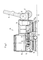
- Fig. 1 eine Maschine in Arbeitsstellung, teilweise im Schnitt,
- Fig. 2 in grösserem Massstab einen Schnitt durch den zentralen Teil der Maschine, und
- Fig. 3 eine Seitenansicht der Maschine in hochgekippter Transportstellung.
- Die in der Zeichnung dargestellte Bodenbearbeitungsmaschine 10 besitzt ein Gehäuse 11, das an seinem einen Ende mit einem Paar frei drehbar gelagerter, koaxial zueinander angeordneten Laufräder 12 (nur eines davon ist in Fig. 1 sichtbar) und mit einer bei 13 auf arretierbare Weise angelenkten Deichsel 14 versehen ist. Auf der Oberseite des bespielsweise aus Druckguss bestehenden Gehäuses 11 ist ein vertikalachsiger Elektromotor 15, beispielsweise ein Doppelkondensatormotor für einphasigen Anschluss, angeflanscht, dessen zugeordnete, aus Anlauf- und Betriebskondensatoren bestehene Kondensatorbatterie mit 16 bezeichnet ist und ebenfalls auf der Oberseite des Gehäuses 11 verankert ist.
- Die Abtriebswelle 17 des Motors 15 erstreckt sich durch das Gehäuse 11 nach unten und trägt eine aufgekeilte Zahnriemenscheibe 18. Diese Zahnriemenscheibe 18 ist mittels eines Zahnriemens 19 formschlüssig an eine weitere Zahnriemenscheibe 20 gekoppelt, die über ein Wälz lager 21 (Fig. 2) auf einem hohlen Wellenstummel 22 mit einem Endflansch 23 drehbar gelagert ist. Der Endflansch 23 ist auf nicht näher dargestellte Weise am Gehäuse 11 fest verankert.
- Ein Antriebsflansch 24, der zugleich als Klemmring für die äussere Laufbahn des Wälzlagers 21 dient, ist an die Unterseite der Zahnriemenscheibe festgeschraubt und mittels einer Ringdichtung 25 gegen den unteren Endbereich des hohlen Wellenstummels 22 abgedichtet.
- Ueber einen Kopplungsring 26 ist eine ringförmige Antriebsscheibe 27 drehfest mit dem Antriebsflansch 24 verbunden. An der Antriebsscheibe 27 ist beispielsweise durch Verklebung, eine elastisch komprimierbare Schicht 28, beispielsweise aus Schaumstoff oder aus Schaumgummi, befestigt, die etwa gleich dick wie die Antriebsscheibe 27 ist. Diese komprimierbare Schicht 28 ist umfangsseitig von einem nach oben abstehenden Randflansch 29 einer Ringscheibe 30 umschlossen, deren obere, ebene Seite an der unteren Seite der komprimierbaren Schicht 28, beispielsweise durch Verklebung, befestigt ist. Dadurch ist die Ringscheibe 30 bezüglich der mit 31 bezeichneten Drehachse gegen die von der komprimierbaren Schicht 28 ausgehende Rückstellkraft beschränkt taumelfähig.
- An der unteren Seite der Ringscheibe 30 ist auf austauschbare Weise, beispielsweise mittels eines Klettenverschlusses 32 (der Einfachheit halber als Schicht dargestellt) ein Arbeitselement 33 befestigt. Wie bereits erwähnt, kann das Arbeitselement 33 aus einem groben Wirrfaservlies (mit oder ohne eingelagertem Abrasiv oder Politurmaterial) oder aus einer Scheibenbürste bestehen.
- Aus Fig. 1 und 2 ist zu ersehen, dass alle Elemente 27, 28, 30, 32 und 33 je einen zur Drehachse koaxialen Durchlass aufweisen, welche Durchlässe einen Raum 34 umschliessen. In diesem Raum 34 ist eine Lenkrolle 35 angeordnet, deren Lenkachse mit der Drehachse 31 zusammenfällt. Der Schaft 36 der Lenkrolle 35 ist längsverschiebbar in der durchgehenden Bohrung 37 des Wellenstummels 22 gelagert und ist seinerseits mit einer Sackbohrung 38 versehen.
- In dieser Sackbohrung 38 steckt der Zylinder 40 eines Gasfederelemtes 39, dessen Kolbenstange 41 in einer Bohrung an der unteren Seite des Gehäuses 11 abgestützt ist. Es versteht sich, dass das Gasfederelement 39 auch umgekehrt eingebaut werden kann. Das Gasfederelement 39 ist so bemessen, dass in der in Fig. 1 und 2 dargestellten Stellung der Maschine, d.h. wenn die Bearbeitungsfläche 42 des Arbeitselementes 33 ganzflächig auf dem zu bearbeitenden Boden 43 aufliegt, die Lenkrolle 35 mit einer Kraft auf den Boden 43 gedrückt wird, die dem Gesamtgewicht der Maschine bis auf einen Rest entspricht, wobei dieser Rest über das Arbeitselement 33 flächig mit einem Auflagedruck von höchstens etwa 0,25 N/cm² abgestützt ist.
- Rein beispielsweise kann das Gesamtgewicht der Maschine etwa bei 400 N liegen, der Aussendurchmesser des Arbeitselementes 43 cm und sein Innendurchmesser etwa 12 cm betragen. Wird das Federelement so bemessen, dass die Lenkrolle 35 mit etwa 200 N gegen den Boden 43 drückt, dann beträgt der mittlere, spezifische Auflagedruck des Arbeitselementes 33 auf den Boden etwa 0,15 N/cm².
- Das Gasfederelement 39 bietet den Vorteil einer praktisch konstanten Federkraft im Bereich des Federweges. Damit das Gasfederelement 39 den Schaft 36 der (unbelasteten) Lenkrolle 35 nicht aus der Bohrung 37 drücken kann, ist das obere Ende des Schaftes 36 mittels eines Federringes 44 gesichert, der bei unbelasteter Lenkrolle 35 gegen eine Schulter 45 im Endflansch 43 anschlägt.
- Wird die Deichsel 14 in der in Fig. 3 gezeigten Bezugslage zum Gehäuse 11 arretiert, lässt sich die ganze Maschine 10 vom Boden 43 hochkippen, bis die Laufräder 12 auf dem Boden 43 anstehen. Dann kann die Maschine 11 bequem transportiert werden.
- Die Schicht 28 dient auch als "Stossdämpfer", der verhindert, dass Vibrationen, die von Unebenheiten des zu bearbeitenden Bodens 43 stammen und auf das Arbeitselement 33 übetragen werden, nicht auf das Gehäuse 11 mit dem Motor 15 und an die Deichsel 14 weiterübertragen werden.
- Der Fahrkranz der Lenkrolle 35 ist bezüglich Breite und Material so zu wählen, dass diese mit Sicherheit keine Fahrspuren in dem zu bearbeitenden Boden hinterlässt. Als zweckmässig hat sich eine Doppellenkrolle erwiesen.
- Bei der beschriebenene Maschine lässt sich mit einer Motorleistung von lediglich etwa 1100 W bei einem Aussen durchmesser des Arbeitselementes von 43 cm dessen Betriebsdrehzahl auf etwa 1000 U/min. festlegen, ohne dass der Motor überlastet würde. Die Maschine ist also besonders für Politurarbeiten geeignet.
Claims (5)
Priority Applications (1)
| Application Number | Priority Date | Filing Date | Title |
|---|---|---|---|
| AT88101283T ATE76729T1 (de) | 1987-03-12 | 1988-01-29 | Bodenbearbeitungsmaschine. |
Applications Claiming Priority (2)
| Application Number | Priority Date | Filing Date | Title |
|---|---|---|---|
| CH935/87 | 1987-03-12 | ||
| CH93587 | 1987-03-12 |
Publications (2)
| Publication Number | Publication Date |
|---|---|
| EP0282707A1 true EP0282707A1 (de) | 1988-09-21 |
| EP0282707B1 EP0282707B1 (de) | 1992-06-03 |
Family
ID=4198598
Family Applications (1)
| Application Number | Title | Priority Date | Filing Date |
|---|---|---|---|
| EP88101283A Expired - Lifetime EP0282707B1 (de) | 1987-03-12 | 1988-01-29 | Bodenbearbeitungsmaschine |
Country Status (8)
| Country | Link |
|---|---|
| EP (1) | EP0282707B1 (de) |
| JP (1) | JPH0651017B2 (de) |
| AT (1) | ATE76729T1 (de) |
| CA (1) | CA1278921C (de) |
| DE (1) | DE3871565D1 (de) |
| ES (1) | ES2031934T3 (de) |
| FI (1) | FI84228C (de) |
| NO (1) | NO171663C (de) |
Cited By (3)
| Publication number | Priority date | Publication date | Assignee | Title |
|---|---|---|---|---|
| WO1991004701A1 (en) * | 1989-10-06 | 1991-04-18 | Numatic International Limited | Floor polishing machine |
| EP0563432A1 (de) * | 1992-04-01 | 1993-10-06 | Penguin Wax Co., Ltd. | Bodenbehandlungsmaschine |
| WO2004105567A1 (en) * | 2003-05-27 | 2004-12-09 | Dyson Technology Limited | A cleaning appliance |
Families Citing this family (2)
| Publication number | Priority date | Publication date | Assignee | Title |
|---|---|---|---|---|
| KR20250152347A (ko) * | 2024-04-16 | 2025-10-23 | 삼성전자주식회사 | 로봇 청소기 |
| GB202415952D0 (en) * | 2024-10-30 | 2024-12-11 | Numatic Int Ltd | Floor scrubber dryer |
Citations (5)
| Publication number | Priority date | Publication date | Assignee | Title |
|---|---|---|---|---|
| CH103622A (de) * | 1923-09-15 | 1924-03-01 | Gaudard Robert | Fussbodenbearbeitungsmaschine. |
| FR1061953A (fr) * | 1952-05-19 | 1954-04-16 | Dispositif pour le nettoiement de grandes surfaces | |
| US4074385A (en) * | 1976-07-06 | 1978-02-21 | Howard Lawrence F | Carpet cleaning brush |
| US4365377A (en) * | 1981-01-13 | 1982-12-28 | H. B. Fuller Company | Floor polishing machine |
| FR2572641A1 (fr) * | 1984-11-07 | 1986-05-09 | Nilfisk Sa Aspirateurs | Plateau a garniture amovible pour le nettoyage des sols |
-
1988
- 1988-01-29 AT AT88101283T patent/ATE76729T1/de not_active IP Right Cessation
- 1988-01-29 ES ES198888101283T patent/ES2031934T3/es not_active Expired - Lifetime
- 1988-01-29 DE DE8888101283T patent/DE3871565D1/de not_active Expired - Lifetime
- 1988-01-29 EP EP88101283A patent/EP0282707B1/de not_active Expired - Lifetime
- 1988-03-07 JP JP63053429A patent/JPH0651017B2/ja not_active Expired - Lifetime
- 1988-03-09 CA CA000560953A patent/CA1278921C/en not_active Expired - Lifetime
- 1988-03-10 FI FI881133A patent/FI84228C/fi not_active IP Right Cessation
- 1988-03-11 NO NO881095A patent/NO171663C/no unknown
Patent Citations (5)
| Publication number | Priority date | Publication date | Assignee | Title |
|---|---|---|---|---|
| CH103622A (de) * | 1923-09-15 | 1924-03-01 | Gaudard Robert | Fussbodenbearbeitungsmaschine. |
| FR1061953A (fr) * | 1952-05-19 | 1954-04-16 | Dispositif pour le nettoiement de grandes surfaces | |
| US4074385A (en) * | 1976-07-06 | 1978-02-21 | Howard Lawrence F | Carpet cleaning brush |
| US4365377A (en) * | 1981-01-13 | 1982-12-28 | H. B. Fuller Company | Floor polishing machine |
| FR2572641A1 (fr) * | 1984-11-07 | 1986-05-09 | Nilfisk Sa Aspirateurs | Plateau a garniture amovible pour le nettoyage des sols |
Cited By (5)
| Publication number | Priority date | Publication date | Assignee | Title |
|---|---|---|---|---|
| WO1991004701A1 (en) * | 1989-10-06 | 1991-04-18 | Numatic International Limited | Floor polishing machine |
| EP0563432A1 (de) * | 1992-04-01 | 1993-10-06 | Penguin Wax Co., Ltd. | Bodenbehandlungsmaschine |
| US5435035A (en) * | 1992-04-01 | 1995-07-25 | Penguin Wax Co., Ltd. | Floor treating machine |
| WO2004105567A1 (en) * | 2003-05-27 | 2004-12-09 | Dyson Technology Limited | A cleaning appliance |
| AU2004243467B2 (en) * | 2003-05-27 | 2007-12-13 | Dyson Technology Limited | A cleaning appliance |
Also Published As
| Publication number | Publication date |
|---|---|
| JPH0651017B2 (ja) | 1994-07-06 |
| FI881133A7 (fi) | 1988-09-13 |
| FI881133A0 (fi) | 1988-03-10 |
| CA1278921C (en) | 1991-01-15 |
| NO881095D0 (no) | 1988-03-11 |
| ES2031934T3 (es) | 1993-01-01 |
| NO171663C (no) | 1993-04-21 |
| NO881095L (no) | 1988-09-13 |
| NO171663B (no) | 1993-01-11 |
| DE3871565D1 (de) | 1992-07-09 |
| ATE76729T1 (de) | 1992-06-15 |
| FI84228B (fi) | 1991-07-31 |
| FI84228C (fi) | 1991-11-11 |
| JPS63230136A (ja) | 1988-09-26 |
| EP0282707B1 (de) | 1992-06-03 |
Similar Documents
| Publication | Publication Date | Title |
|---|---|---|
| EP0619979B1 (de) | Bodenbearbeitungsmaschine | |
| DE2559983C3 (de) | Boden-, insbesondere Teppichkehrmaschine | |
| DE69807051T2 (de) | Bodenflächenbearbeitungsgerät | |
| DE3016654C2 (de) | ||
| DE69935990T2 (de) | Fahrbare maschine zum abschleifen | |
| CH666802A5 (de) | Bohnervorrichtung zum bohnern gewachster boeden. | |
| DE69009810T2 (de) | Maschine und Antriebsscheibe zum Behandeln von Fussböden. | |
| EP2349642A1 (de) | Deckenschleifmaschine | |
| DE69019821T2 (de) | Vorrichtung zur behandlung von fussböden. | |
| DE2345639A1 (de) | Staubsauger | |
| EP0631485B1 (de) | Fussboden-reinigungsmaschine | |
| EP0282707B1 (de) | Bodenbearbeitungsmaschine | |
| DE2455200A1 (de) | Regelungsanordnung | |
| DE2121182C3 (de) | Kupplungsriemenscheibe für einen Riementrieb | |
| DE3145151A1 (de) | Antreibbare walze zum ueberschleifen oder polieren der oberflaeche einer fahrzeugkarosserie oder dergleichen | |
| DE19729199A1 (de) | Fußbodenbearbeitungsmaschine | |
| DE1628750A1 (de) | Umlaufende Bodenpflegemaschine | |
| CH103622A (de) | Fussbodenbearbeitungsmaschine. | |
| DE3638666C2 (de) | ||
| DE653050C (de) | Ventilsitzschleifmaschine | |
| DE4117776A1 (de) | Parkettschleifmaschine | |
| DE202004015950U1 (de) | Polier- und Reinigungsmaschine | |
| DE20300379U1 (de) | Werkzeug für das Abscheren und/oder Egalisieren von Oberflächen | |
| DE1205664B (de) | Maschine zum Bearbeiten und Pflegen von Fussboeden | |
| DE2709193A1 (de) | Vorrichtung zum reinigen, schleifen und polieren von grossflaechen |
Legal Events
| Date | Code | Title | Description |
|---|---|---|---|
| PUAI | Public reference made under article 153(3) epc to a published international application that has entered the european phase |
Free format text: ORIGINAL CODE: 0009012 |
|
| AK | Designated contracting states |
Kind code of ref document: A1 Designated state(s): AT BE CH DE ES FR GB IT LI NL SE |
|
| 17P | Request for examination filed |
Effective date: 19880928 |
|
| 17Q | First examination report despatched |
Effective date: 19900327 |
|
| GRAA | (expected) grant |
Free format text: ORIGINAL CODE: 0009210 |
|
| AK | Designated contracting states |
Kind code of ref document: B1 Designated state(s): AT BE CH DE ES FR GB IT LI NL SE |
|
| REF | Corresponds to: |
Ref document number: 76729 Country of ref document: AT Date of ref document: 19920615 Kind code of ref document: T |
|
| ET | Fr: translation filed | ||
| REF | Corresponds to: |
Ref document number: 3871565 Country of ref document: DE Date of ref document: 19920709 |
|
| ITF | It: translation for a ep patent filed | ||
| GBT | Gb: translation of ep patent filed (gb section 77(6)(a)/1977) | ||
| REG | Reference to a national code |
Ref country code: ES Ref legal event code: FG2A Ref document number: 2031934 Country of ref document: ES Kind code of ref document: T3 |
|
| PLBE | No opposition filed within time limit |
Free format text: ORIGINAL CODE: 0009261 |
|
| STAA | Information on the status of an ep patent application or granted ep patent |
Free format text: STATUS: NO OPPOSITION FILED WITHIN TIME LIMIT |
|
| 26N | No opposition filed | ||
| EAL | Se: european patent in force in sweden |
Ref document number: 88101283.5 |
|
| PGFP | Annual fee paid to national office [announced via postgrant information from national office to epo] |
Ref country code: GB Payment date: 19961212 Year of fee payment: 10 |
|
| PGFP | Annual fee paid to national office [announced via postgrant information from national office to epo] |
Ref country code: SE Payment date: 19961216 Year of fee payment: 10 Ref country code: FR Payment date: 19961216 Year of fee payment: 10 |
|
| PGFP | Annual fee paid to national office [announced via postgrant information from national office to epo] |
Ref country code: DE Payment date: 19961217 Year of fee payment: 10 |
|
| PGFP | Annual fee paid to national office [announced via postgrant information from national office to epo] |
Ref country code: BE Payment date: 19961219 Year of fee payment: 10 |
|
| PGFP | Annual fee paid to national office [announced via postgrant information from national office to epo] |
Ref country code: NL Payment date: 19961223 Year of fee payment: 10 |
|
| PGFP | Annual fee paid to national office [announced via postgrant information from national office to epo] |
Ref country code: AT Payment date: 19961224 Year of fee payment: 10 |
|
| PGFP | Annual fee paid to national office [announced via postgrant information from national office to epo] |
Ref country code: ES Payment date: 19970129 Year of fee payment: 10 |
|
| PGFP | Annual fee paid to national office [announced via postgrant information from national office to epo] |
Ref country code: CH Payment date: 19970130 Year of fee payment: 10 |
|
| PG25 | Lapsed in a contracting state [announced via postgrant information from national office to epo] |
Ref country code: GB Free format text: LAPSE BECAUSE OF NON-PAYMENT OF DUE FEES Effective date: 19980129 Ref country code: AT Free format text: LAPSE BECAUSE OF NON-PAYMENT OF DUE FEES Effective date: 19980129 |
|
| PG25 | Lapsed in a contracting state [announced via postgrant information from national office to epo] |
Ref country code: SE Free format text: LAPSE BECAUSE OF NON-PAYMENT OF DUE FEES Effective date: 19980130 Ref country code: ES Free format text: LAPSE BECAUSE OF EXPIRATION OF PROTECTION Effective date: 19980130 |
|
| PG25 | Lapsed in a contracting state [announced via postgrant information from national office to epo] |
Ref country code: LI Free format text: LAPSE BECAUSE OF NON-PAYMENT OF DUE FEES Effective date: 19980131 Ref country code: FR Free format text: THE PATENT HAS BEEN ANNULLED BY A DECISION OF A NATIONAL AUTHORITY Effective date: 19980131 Ref country code: CH Free format text: LAPSE BECAUSE OF NON-PAYMENT OF DUE FEES Effective date: 19980131 Ref country code: BE Free format text: LAPSE BECAUSE OF NON-PAYMENT OF DUE FEES Effective date: 19980131 |
|
| BERE | Be: lapsed |
Owner name: DIETHELM & CO. A.G. Effective date: 19980131 |
|
| PG25 | Lapsed in a contracting state [announced via postgrant information from national office to epo] |
Ref country code: NL Free format text: LAPSE BECAUSE OF NON-PAYMENT OF DUE FEES Effective date: 19980801 |
|
| REG | Reference to a national code |
Ref country code: CH Ref legal event code: PL |
|
| GBPC | Gb: european patent ceased through non-payment of renewal fee |
Effective date: 19980129 |
|
| NLV4 | Nl: lapsed or anulled due to non-payment of the annual fee |
Effective date: 19980801 |
|
| PG25 | Lapsed in a contracting state [announced via postgrant information from national office to epo] |
Ref country code: DE Free format text: LAPSE BECAUSE OF NON-PAYMENT OF DUE FEES Effective date: 19981001 |
|
| EUG | Se: european patent has lapsed |
Ref document number: 88101283.5 |
|
| REG | Reference to a national code |
Ref country code: FR Ref legal event code: ST |
|
| REG | Reference to a national code |
Ref country code: ES Ref legal event code: FD2A Effective date: 20000201 |
|
| PG25 | Lapsed in a contracting state [announced via postgrant information from national office to epo] |
Ref country code: IT Free format text: LAPSE BECAUSE OF NON-PAYMENT OF DUE FEES;WARNING: LAPSES OF ITALIAN PATENTS WITH EFFECTIVE DATE BEFORE 2007 MAY HAVE OCCURRED AT ANY TIME BEFORE 2007. THE CORRECT EFFECTIVE DATE MAY BE DIFFERENT FROM THE ONE RECORDED. Effective date: 20050129 |