EP0282935A2 - Vorrichtung und Verfahren zum Verbreitern von Fahrbahnen - Google Patents
Vorrichtung und Verfahren zum Verbreitern von Fahrbahnen Download PDFInfo
- Publication number
- EP0282935A2 EP0282935A2 EP88103957A EP88103957A EP0282935A2 EP 0282935 A2 EP0282935 A2 EP 0282935A2 EP 88103957 A EP88103957 A EP 88103957A EP 88103957 A EP88103957 A EP 88103957A EP 0282935 A2 EP0282935 A2 EP 0282935A2
- Authority
- EP
- European Patent Office
- Prior art keywords
- wall
- embankment
- element according
- tension element
- tension
- Prior art date
- Legal status (The legal status is an assumption and is not a legal conclusion. Google has not performed a legal analysis and makes no representation as to the accuracy of the status listed.)
- Withdrawn
Links
- 238000000034 method Methods 0.000 title claims abstract description 20
- 239000000463 material Substances 0.000 claims abstract description 10
- 238000005266 casting Methods 0.000 claims abstract description 5
- 238000004873 anchoring Methods 0.000 claims description 10
- 210000002445 nipple Anatomy 0.000 claims description 8
- 230000001681 protective effect Effects 0.000 claims description 6
- XLYOFNOQVPJJNP-UHFFFAOYSA-N water Substances O XLYOFNOQVPJJNP-UHFFFAOYSA-N 0.000 claims description 6
- 239000004567 concrete Substances 0.000 claims description 4
- 230000008878 coupling Effects 0.000 claims description 4
- 238000010168 coupling process Methods 0.000 claims description 4
- 238000005859 coupling reaction Methods 0.000 claims description 4
- 238000011049 filling Methods 0.000 claims description 4
- 239000004568 cement Substances 0.000 claims description 3
- 238000001914 filtration Methods 0.000 claims description 3
- 239000011440 grout Substances 0.000 claims description 3
- 239000003822 epoxy resin Substances 0.000 claims description 2
- LNEPOXFFQSENCJ-UHFFFAOYSA-N haloperidol Chemical compound C1CC(O)(C=2C=CC(Cl)=CC=2)CCN1CCCC(=O)C1=CC=C(F)C=C1 LNEPOXFFQSENCJ-UHFFFAOYSA-N 0.000 claims description 2
- 239000004745 nonwoven fabric Substances 0.000 claims description 2
- 229920000647 polyepoxide Polymers 0.000 claims description 2
- 239000011241 protective layer Substances 0.000 claims 2
- 230000000717 retained effect Effects 0.000 claims 2
- 230000004308 accommodation Effects 0.000 claims 1
- 239000010410 layer Substances 0.000 claims 1
- 239000003566 sealing material Substances 0.000 claims 1
- 239000011248 coating agent Substances 0.000 description 2
- 238000000576 coating method Methods 0.000 description 2
- 230000000694 effects Effects 0.000 description 2
- 238000012986 modification Methods 0.000 description 2
- 230000004048 modification Effects 0.000 description 2
- 239000011150 reinforced concrete Substances 0.000 description 2
- 238000007789 sealing Methods 0.000 description 2
- 229920001875 Ebonite Polymers 0.000 description 1
- 210000000481 breast Anatomy 0.000 description 1
- 230000000295 complement effect Effects 0.000 description 1
- 230000007613 environmental effect Effects 0.000 description 1
- 238000000605 extraction Methods 0.000 description 1
- 239000004744 fabric Substances 0.000 description 1
- 238000003780 insertion Methods 0.000 description 1
- 230000037431 insertion Effects 0.000 description 1
- 230000000670 limiting effect Effects 0.000 description 1
- 238000011068 loading method Methods 0.000 description 1
- 239000000314 lubricant Substances 0.000 description 1
- 239000002245 particle Substances 0.000 description 1
- 229920002635 polyurethane Polymers 0.000 description 1
- 239000004814 polyurethane Substances 0.000 description 1
- 238000011084 recovery Methods 0.000 description 1
- 239000000565 sealant Substances 0.000 description 1
- 239000007787 solid Substances 0.000 description 1
Images

Classifications
-
- E—FIXED CONSTRUCTIONS
- E02—HYDRAULIC ENGINEERING; FOUNDATIONS; SOIL SHIFTING
- E02D—FOUNDATIONS; EXCAVATIONS; EMBANKMENTS; UNDERGROUND OR UNDERWATER STRUCTURES
- E02D5/00—Bulkheads, piles, or other structural elements specially adapted to foundation engineering
- E02D5/74—Means for anchoring structural elements or bulkheads
- E02D5/76—Anchorings for bulkheads or sections thereof in as much as specially adapted therefor
-
- E—FIXED CONSTRUCTIONS
- E01—CONSTRUCTION OF ROADS, RAILWAYS, OR BRIDGES
- E01C—CONSTRUCTION OF, OR SURFACES FOR, ROADS, SPORTS GROUNDS, OR THE LIKE; MACHINES OR AUXILIARY TOOLS FOR CONSTRUCTION OR REPAIR
- E01C1/00—Design or layout of roads, e.g. for noise abatement, for gas absorption
- E01C1/002—Design or lay-out of roads, e.g. street systems, cross-sections ; Design for noise abatement, e.g. sunken road
-
- E—FIXED CONSTRUCTIONS
- E01—CONSTRUCTION OF ROADS, RAILWAYS, OR BRIDGES
- E01C—CONSTRUCTION OF, OR SURFACES FOR, ROADS, SPORTS GROUNDS, OR THE LIKE; MACHINES OR AUXILIARY TOOLS FOR CONSTRUCTION OR REPAIR
- E01C3/00—Foundations for pavings
-
- E—FIXED CONSTRUCTIONS
- E02—HYDRAULIC ENGINEERING; FOUNDATIONS; SOIL SHIFTING
- E02D—FOUNDATIONS; EXCAVATIONS; EMBANKMENTS; UNDERGROUND OR UNDERWATER STRUCTURES
- E02D29/00—Independent underground or underwater structures; Retaining walls
- E02D29/02—Retaining or protecting walls
- E02D29/0258—Retaining or protecting walls characterised by constructional features
- E02D29/0266—Retaining or protecting walls characterised by constructional features made up of preformed elements
-
- E—FIXED CONSTRUCTIONS
- E02—HYDRAULIC ENGINEERING; FOUNDATIONS; SOIL SHIFTING
- E02D—FOUNDATIONS; EXCAVATIONS; EMBANKMENTS; UNDERGROUND OR UNDERWATER STRUCTURES
- E02D29/00—Independent underground or underwater structures; Retaining walls
- E02D29/02—Retaining or protecting walls
- E02D29/0258—Retaining or protecting walls characterised by constructional features
- E02D29/0275—Retaining or protecting walls characterised by constructional features cast in situ
-
- Y—GENERAL TAGGING OF NEW TECHNOLOGICAL DEVELOPMENTS; GENERAL TAGGING OF CROSS-SECTIONAL TECHNOLOGIES SPANNING OVER SEVERAL SECTIONS OF THE IPC; TECHNICAL SUBJECTS COVERED BY FORMER USPC CROSS-REFERENCE ART COLLECTIONS [XRACs] AND DIGESTS
- Y02—TECHNOLOGIES OR APPLICATIONS FOR MITIGATION OR ADAPTATION AGAINST CLIMATE CHANGE
- Y02A—TECHNOLOGIES FOR ADAPTATION TO CLIMATE CHANGE
- Y02A30/00—Adapting or protecting infrastructure or their operation
- Y02A30/60—Planning or developing urban green infrastructure
Definitions
- the present invention relates to a process and apparatus for widening roadways.
- the technical aim of the present invention is to provide a process which obviates, or at least significantly reduces, the above described disadvantages.
- an object of the present invention is to provide a process which allows to widen the roadway in times significantly shorter than those required by a conventional system.
- a further object of the present invention is to provide an apparatus to execute such a process.
- a process for widening roadways characterized in that it comprises the steps of digging a trench of adequate depth in the slope of the embankment at a distance from the existing roadway corresponding to the selected widening, building a wall in said trench which rises substantially to the level of the roadway and delimits a channel with the slope of the embankment, anchoring said wall to the road embankment by means of tension elements, filling the channel with material and completing the road paving up to said wall.
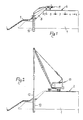
- FIG. 1 indicates the road embankment on which there runs the carriageway 2, composed of two lanes 3, 4 and of an emergency lane 5.
- the directional separator lane 6 is to the side of the lane 4 (passing lane), while the verge 7 is to the side of the emergency lane 6.
- the embankment 1 forms a slope 8 which is covered with a protection layer 9 which has inferior mechanical characteristics with respect to those of the embankment 1.
- the process according to the invention comprises the steps of (see figure 1) removing the upper region of the protection 9 (delimited by the broken line) until the uncovering of the embankment 1 is achieved, and then digging a trench 10 at a distance from the outer edge of the emergency lane 5 corresponding to the desired widening.
- the trench 10 can be dug by an excavator 11 equipped with a clamshell bucket or a mill which advances along the emergency lane.
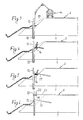
- Prefabricated walls 12, the structure whereof will be described in greater detail hereinafter, are then positioned along a vertical plane in the trench 10 (see figure 2).
- the walls can be positioned by means of a crane 13.
- the walls 12 are provided with transfer passages to allow the rise of the concrete on both sides of the wall even when it is poured from the inner side.
- the crane 13, the excavator 11 and the truck mixer 14 have dimensions no greater than the width of the lanes 3 and 5 so that vehicle traffic can proceed in the passing lane 4 without being subject to interruptions.
- the top of the wall 12 is substantially at the level of the paving of the carriageway so that a channel 15 is formed between the wall 12 and the slope 8 of the embankment 1, and is then filled with stabilized material to form a wedge 16 (figure 4) defining a work level for the placement of tension elements 17 (figure 5) by means of which the walls are anchored to the embankment 1.
- the channel 15 is filled with stabilized material and the wall covering element 18, the water collection gutter 19, the guardrail 20 and the paving 21 are completed.
- the widened region is particularly stable since the walls sink into stabilized and compacted material with high mechanical characteristics.
- the wall 12 besides with prefabricated modular elements, can also be provided with on-site casting.
- a prefabricated element suitable for the purpose comprises a rectangular panel 22, provided with a central rib 23 and with two lateral ribs 24, 25, all in reinforced concrete.
- a groove 26 and respectively a ridge 27 are provided in the outer faces of the ribs 24, 25, that is to say on the heads of the element 12.
- the cross sections of the groove and of the ridge are mutually complementary so that, by placing the elements 22 adjacent to one other, the ridge of one element inserts into the groove of the adjacent one thus providing a continuous wall.
- the ribs 23-25 extend downwards beyond the lower edge of the panel 22 so that two loops 28, 29 form which serve for the transfer of the concrete during the sealing step (see figure 3).
- Two openings 30, 31 are provided for the same purpose in the panel 22 at an appropriate distance from the upper edge.
- Lifting bushes 32 are sunk in the panel 22 for the placement of the modular elements. Further bushes are provided at the top of the modular element at the lateral ribs 24, 25. The bushes are shaped to allow the coupling of lifting elements both during the operations of loading of the modular elements on the transport vehicles and for the positioning of the modular elements during the placement in the trench.
- the covering or protective element 18 is constituted by a sort of large bent tile having a cross section in the shape of an inverted U, which is rested on the top of the modular elements 12 with the interposition of plugs 33 which engage in appropriate recesses provided at the top of the ribs 24, 25.
- the plugs 33 are provided in hard rubber or the like.
- the modular elements may be dry-coupled or connected with sealants.
- a strip 35 in filtering material is arranged in the junction and has the purpose of retaining the solid particles and of allowing the water which may infiltrate in the embankment to pass, avoiding thereby the washout of the filling material through the slit of the junction.
- the strip 35 is provided in open-cell polyurethane or the like.
- Figure 11 illustrates a solution in which both lateral ribs of the modular elements have, on the heads, respective grooves from which brackets 36 protrude.
- the gutter 19 for the conveyance of the water is constituted by a slab in which a step 38 defines a drainage channel (see figure 12).
- the downflow of the water at the sides of the roadway occurs through channel 39 which cut the step 38 and continue with a suitable inclination on the tiles.
- the tiles at preset distances, will have drainage channels which continue outside the tiles with gargoyles 40 which convey the water towards an underlying downflow offlet 41.
- the tiles 18 can be provided monolithically with a guardrail in reinforced concrete of the so-called "New Jersey" type.
- the guardrail will be anchored to the top of the modular elements 12 by means of anchoring bolts 43 driven through the base of the guardrail and engaging in respective dead holes 44 formed in the ribs 24, 25 of the modular elements.
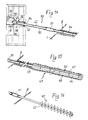
- a so-called active part 45 (that is the part for anchoring to the ground) of a tension element, comprises a rod 46 adapted to be inserted in a hole 47 provided in the slope of the embankment.
- a bag of non-woven fabric is arranged around the end of the rod 46, fixed thereto by a clamp 49.
- a tube 50 extends in the bag 48 which, by means of pump means, cement grout is injected under pressure and, by the filtering effect performed by the fabric of the bag, determines a firm anchoring in the ground.
- the rod 46 has a threaded end which protrudes from the hole 47 and on which a nipple 51 is screwed in which a rod 52 of the so-called passive part 53 of the tension element is also screwed.
- the ends of the rods 46 and 52 which engage in the nipple 51 have counterposed threads which allow, by screwing or unscrewing the nipple, to tighten or slacken the tension element.
- the end of the rod 52 opposite to the nipple 51 is also threaded and engages in a recess 55 of said rib through an opening 54 provided in the central rib 23 of the modular element 12.
- the recess 55 is constituted by a box-like frame 56 in the shape of an hourglass with outer ridges 57 and having a neck 58 which acts as abutment for a nut 59 screwed onto the end of the rod 52.
- the recess 55 contains a lubricant and is closed by a door 60, while an annular plug 61 closes the opening 54 for the insertion of the rod.
- the description tension element is completed by a coating 62 intended to protect the passive part 53 and the active part 45 which remains external to the sac 48, as well as the nipple 51.
- the coating 62 is provided with epoxy resins or with hot-galvanization or by means of a PVC sheathing.
- the nipple 51 has the function of putting under traction the tension element during the placement of the walls 12, while by means of the nut 59 it is possible to recover any relaxations which may intervene in the course of time, the nut 59 being always accessible through the door 60.
- the active part of the tension element may be constituted by a screw 63 (see figure 16) which is screwed into the embankment and then connected to the passive part.
- the nut 59 has a hexagonal portion 64 for the engagement of an adapted screwing tool and a hemispherical portion for abutment on the neck 58.
- Said hemispherical shape in combination with the shape of the frame 57, diverging towards the opening 54, allows the recovery of any axial offset of the tension element with respect to the frame.
Landscapes
- Engineering & Computer Science (AREA)
- Structural Engineering (AREA)
- Civil Engineering (AREA)
- Life Sciences & Earth Sciences (AREA)
- General Life Sciences & Earth Sciences (AREA)
- Mining & Mineral Resources (AREA)
- Paleontology (AREA)
- General Engineering & Computer Science (AREA)
- Environmental & Geological Engineering (AREA)
- Architecture (AREA)
- Road Paving Structures (AREA)
- Retaining Walls (AREA)
Applications Claiming Priority (2)
| Application Number | Priority Date | Filing Date | Title |
|---|---|---|---|
| IT8703404A IT1207642B (it) | 1987-03-20 | 1987-03-20 | Procedimento per realizzare l'allargamento di una sede stradale, in particoalre di un'autostrada ed elementi strutturali per l'esecuzione di tale procedimento |
| IT340487 | 1987-03-20 |
Publications (2)
| Publication Number | Publication Date |
|---|---|
| EP0282935A2 true EP0282935A2 (de) | 1988-09-21 |
| EP0282935A3 EP0282935A3 (de) | 1989-11-23 |
Family
ID=11106529
Family Applications (1)
| Application Number | Title | Priority Date | Filing Date |
|---|---|---|---|
| EP88103957A Withdrawn EP0282935A3 (de) | 1987-03-20 | 1988-03-12 | Vorrichtung und Verfahren zum Verbreitern von Fahrbahnen |
Country Status (4)
| Country | Link |
|---|---|
| US (1) | US4848972A (de) |
| EP (1) | EP0282935A3 (de) |
| JP (1) | JPS63277301A (de) |
| IT (1) | IT1207642B (de) |
Cited By (11)
| Publication number | Priority date | Publication date | Assignee | Title |
|---|---|---|---|---|
| NL1025567C2 (nl) * | 2003-05-15 | 2005-01-05 | Denys Nv | Werkwijze voor het bouwen van een tunnel onder een rijweg en welfsel daarbij toegepast. |
| FR2890399A1 (fr) * | 2005-09-05 | 2007-03-09 | Ims Rn Ingenierie Des Mouvemen | Structure d'elargissement d'une route |
| WO2011140979A1 (zh) * | 2010-05-12 | 2011-11-17 | Chang Yu-Shun | 绿化生态布加固方法及结构 |
| CN102352590A (zh) * | 2011-07-27 | 2012-02-15 | 河南省交通规划勘察设计院有限责任公司 | 采用桩板式挡墙进行高填方路基拼接的方法 |
| CN102359046A (zh) * | 2011-07-27 | 2012-02-22 | 河南省交通规划勘察设计院有限责任公司 | 一种高填方路基拼接方法 |
| CN103526773A (zh) * | 2013-10-22 | 2014-01-22 | 青岛理工大学 | 悬臂式垂向锚杆复合挡土墙及其设计与施工方法 |
| WO2014195773A1 (es) * | 2013-06-05 | 2014-12-11 | Tecnosuelo, S.A. De C.V. | Procedimiento para ampliación y estabilización de terrenos planos en zonas de topografía accidentada |
| CN105648868A (zh) * | 2016-02-02 | 2016-06-08 | 上海建工集团股份有限公司 | 一种公路基层的拼宽施工方法 |
| CN106522055A (zh) * | 2016-11-09 | 2017-03-22 | 郭昆朋 | 公路加宽路基的施工方法 |
| CN113605161A (zh) * | 2021-05-27 | 2021-11-05 | 中铁九局集团第一建设有限公司 | 一种公路扩建的路基拼接方法 |
| CN117051633A (zh) * | 2023-06-21 | 2023-11-14 | 中能建路桥工程有限公司 | 一种高速公路路基拓宽结构 |
Families Citing this family (13)
| Publication number | Priority date | Publication date | Assignee | Title |
|---|---|---|---|---|
| US5158399A (en) * | 1991-12-27 | 1992-10-27 | Flores Raymond H | Method for erecting a below grade wall |
| US5537788A (en) * | 1992-08-28 | 1996-07-23 | Jte, Inc. | System and method for widening a highway and supporting a sound wall |
| US6299386B1 (en) | 1999-06-09 | 2001-10-09 | R. John Byrne | Method and apparatus for a shoring wall |
| JP2015101880A (ja) * | 2013-11-25 | 2015-06-04 | フリー工業株式会社 | 擁壁の構造とその構築方法 |
| JP6412398B2 (ja) * | 2014-10-21 | 2018-10-24 | ランデス株式会社 | 道路拡幅ブロック |
| JP6373163B2 (ja) * | 2014-10-28 | 2018-08-15 | 日本興業株式会社 | 張出歩道ブロック |
| CN104894935B (zh) * | 2015-04-03 | 2017-07-28 | 重庆大学 | 一种既有高速公路或铁路路堤轻质化沉降控制方法 |
| CN110820432B (zh) * | 2019-12-04 | 2024-09-17 | 中铁二院工程集团有限责任公司 | 一种硬塑状土质地基既有高铁路堤帮宽结构及构筑方法 |
| CN112681043B (zh) * | 2020-12-18 | 2022-08-23 | 湖北省路桥集团有限公司 | 路基拼接拓宽结构及施工方法 |
| CN113494035B (zh) * | 2021-06-30 | 2023-07-04 | 徐州市政建设集团有限责任公司 | 一种市政道路扩建结构及道路扩建方法 |
| CN114658055A (zh) * | 2022-03-31 | 2022-06-24 | 中国化学工程第十四建设有限公司 | 改扩建高速公路岩石路堑开挖机械凿除方法 |
| CN114855532A (zh) * | 2022-04-15 | 2022-08-05 | 重庆昂然建筑工程有限公司 | 一种农村旧路改建施工方法 |
| CN115976987A (zh) * | 2023-02-03 | 2023-04-18 | 山东省交通规划设计院集团有限公司 | 一种改扩建老路u型桥台拼接施工工法 |
Family Cites Families (13)
| Publication number | Priority date | Publication date | Assignee | Title |
|---|---|---|---|---|
| FR798811A (fr) * | 1935-02-26 | 1936-05-27 | Mode de construction de digues-revêtements sur littoral de dunes | |
| AT290608B (de) * | 1967-09-13 | 1971-06-11 | Comar Reg Trust | Verfahren zur Herstellung von unterhalb von Verkehrsflächen od.dgl. liegenden Tiefbauwerken und Auflagerbalken zur Durchfüfrung des Verfahrens |
| IT1025608B (it) * | 1974-11-12 | 1978-08-30 | Alpina Spa | Elementi prefabbricati per la co struzione di strutture in trincea e procedimento relativo |
| AT334413B (de) * | 1975-07-21 | 1976-01-10 | Ebenseer Betonwerke Gmbh | Bruckentragwerk |
| US4051570A (en) * | 1976-12-27 | 1977-10-04 | Hilfiker Pipe Co. | Road bridge construction with precast concrete modules |
| US4132498A (en) * | 1977-02-17 | 1979-01-02 | Shigeru Sugimura | Earth anchor and method of setting and removing same |
| DE7705157U1 (de) * | 1977-02-19 | 1977-08-04 | Bauteile Fleischmann Gmbh, 8782 Karlstadt | Vorgefertigte Betonbauteile zur Herstellung von Wänden, Wällen, Böschungen o.dgl., z.B. für die Zwecke des Lärmschutzes |
| DE2715967C2 (de) * | 1977-04-09 | 1979-05-31 | Brueckner Grundbau Gmbh, 4300 Essen | Vorrichtung zum wasserdichten Durchführen eines VerpreBankers durch eine wasserrückhaltende Baugrubenwand, insbesondere Schlitzwand aus Stahlbeton |
| FR2453938A1 (fr) * | 1979-02-15 | 1980-11-07 | Staempfli Alexandre | Console de soutenement |
| US4260296A (en) * | 1979-06-08 | 1981-04-07 | The Reinforced Earth Company | Adjustable cap for retaining walls |
| US4369004A (en) * | 1980-10-01 | 1983-01-18 | Schnabel Foundation Company | Earth retaining method and structure |
| FR2540911A1 (fr) * | 1983-02-11 | 1984-08-17 | Morillon Corvol Courbot Entr | Procede pour la realisation de l'etancheite entre les panneaux prefabriques d'une paroi dans le sol, et joint d'etancheite pour la mise en oeuvre de ce procede |
| US4604841A (en) * | 1983-04-01 | 1986-08-12 | Barnoff Robert M | Continuous, precast, prestressed concrete bridge deck panel forms, precast parapets, and method of construction |
-
1987
- 1987-03-20 IT IT8703404A patent/IT1207642B/it active
-
1988
- 1988-03-12 EP EP88103957A patent/EP0282935A3/de not_active Withdrawn
- 1988-03-14 JP JP63061741A patent/JPS63277301A/ja active Pending
- 1988-03-14 US US07/167,758 patent/US4848972A/en not_active Expired - Fee Related
Cited By (14)
| Publication number | Priority date | Publication date | Assignee | Title |
|---|---|---|---|---|
| NL1025567C2 (nl) * | 2003-05-15 | 2005-01-05 | Denys Nv | Werkwijze voor het bouwen van een tunnel onder een rijweg en welfsel daarbij toegepast. |
| BE1015517A3 (nl) * | 2003-05-15 | 2005-05-03 | Denys Nv | Werkwijze voor het bouwen van een tunnel onder een rijweg en welfsel daarbij toegepast. |
| FR2890399A1 (fr) * | 2005-09-05 | 2007-03-09 | Ims Rn Ingenierie Des Mouvemen | Structure d'elargissement d'une route |
| WO2011140979A1 (zh) * | 2010-05-12 | 2011-11-17 | Chang Yu-Shun | 绿化生态布加固方法及结构 |
| CN102352590B (zh) * | 2011-07-27 | 2013-09-18 | 河南省交通规划勘察设计院有限责任公司 | 采用桩板式挡墙进行高填方路基拼接的方法 |
| CN102359046A (zh) * | 2011-07-27 | 2012-02-22 | 河南省交通规划勘察设计院有限责任公司 | 一种高填方路基拼接方法 |
| CN102352590A (zh) * | 2011-07-27 | 2012-02-15 | 河南省交通规划勘察设计院有限责任公司 | 采用桩板式挡墙进行高填方路基拼接的方法 |
| WO2014195773A1 (es) * | 2013-06-05 | 2014-12-11 | Tecnosuelo, S.A. De C.V. | Procedimiento para ampliación y estabilización de terrenos planos en zonas de topografía accidentada |
| CN103526773A (zh) * | 2013-10-22 | 2014-01-22 | 青岛理工大学 | 悬臂式垂向锚杆复合挡土墙及其设计与施工方法 |
| CN105648868A (zh) * | 2016-02-02 | 2016-06-08 | 上海建工集团股份有限公司 | 一种公路基层的拼宽施工方法 |
| CN105648868B (zh) * | 2016-02-02 | 2018-07-17 | 上海建工集团股份有限公司 | 一种公路基层的拼宽施工方法 |
| CN106522055A (zh) * | 2016-11-09 | 2017-03-22 | 郭昆朋 | 公路加宽路基的施工方法 |
| CN113605161A (zh) * | 2021-05-27 | 2021-11-05 | 中铁九局集团第一建设有限公司 | 一种公路扩建的路基拼接方法 |
| CN117051633A (zh) * | 2023-06-21 | 2023-11-14 | 中能建路桥工程有限公司 | 一种高速公路路基拓宽结构 |
Also Published As
| Publication number | Publication date |
|---|---|
| US4848972A (en) | 1989-07-18 |
| EP0282935A3 (de) | 1989-11-23 |
| JPS63277301A (ja) | 1988-11-15 |
| IT8703404A0 (it) | 1987-03-20 |
| IT1207642B (it) | 1989-05-25 |
Similar Documents
| Publication | Publication Date | Title |
|---|---|---|
| EP0282935A2 (de) | Vorrichtung und Verfahren zum Verbreitern von Fahrbahnen | |
| US4964750A (en) | Traffic barrier and method of construction | |
| US5131786A (en) | Traffic barrier and method of construction | |
| US5471811A (en) | Combination traffic barrier and retaining wall and method of construction | |
| US12421671B2 (en) | In-situ reconstruction and extension structure of embankment and construction method thereof | |
| US3695153A (en) | Drainage catch basins | |
| JP2518390Y2 (ja) | 張出歩道ブロック及びそれを用いた張出歩道構造 | |
| JP6340044B2 (ja) | 張出歩道構成体と、これらを用いた張出歩道の建設方法 | |
| KR100592416B1 (ko) | 보도가 확보되지 않은 협소한 도로에서 콘크리트옹벽블록과 트러스형 받침대를 이용한 보도확보 및차도확폭 시공방법 | |
| JPH0258606A (ja) | 中央分離帯の改修方法 | |
| JP2597076B2 (ja) | 側溝及び側溝の製造方法 | |
| KR102073887B1 (ko) | 도로연속배수시설의 타설장치 | |
| KR100561716B1 (ko) | 측구 | |
| JPH0743181Y2 (ja) | 擁 壁 | |
| KR100769944B1 (ko) | 생태 환경을 고려한 경관 옹벽 및 이를 이용한 보도 확장시공방법 | |
| RU2841439C1 (ru) | Способ строительства дороги | |
| CN112031002A (zh) | 桩承式生态护坡及施工方法 | |
| JP4468133B2 (ja) | 張出車道ブロック及び該ブロックを用いた張出車道の施工方法 | |
| JP2000297403A (ja) | 通路および通路の施工方法 | |
| CN115506193B (zh) | 山岭地区高陡边坡地段的装配式施工便道的施工方法 | |
| CN222065174U (zh) | 一种墩台错孔布置的正交桥于路桥交界处的施工结构 | |
| CN217710841U (zh) | 应用于跨地下空间顶板渠道的防水抗滑结构 | |
| JP2612600B2 (ja) | 中央分離帯の改修方法 | |
| KR20040052885A (ko) | 기능성 경계석을 가지는 엘형 측구 및 그 시공 방법 | |
| CN216338785U (zh) | 一种基于山区高陡边坡的路基构造 |
Legal Events
| Date | Code | Title | Description |
|---|---|---|---|
| PUAI | Public reference made under article 153(3) epc to a published international application that has entered the european phase |
Free format text: ORIGINAL CODE: 0009012 |
|
| AK | Designated contracting states |
Kind code of ref document: A2 Designated state(s): AT BE CH DE ES FR GB GR LI LU NL SE |
|
| PUAL | Search report despatched |
Free format text: ORIGINAL CODE: 0009013 |
|
| AK | Designated contracting states |
Kind code of ref document: A3 Designated state(s): AT BE CH DE ES FR GB GR LI LU NL SE |
|
| 17P | Request for examination filed |
Effective date: 19900208 |
|
| 17Q | First examination report despatched |
Effective date: 19910607 |
|
| STAA | Information on the status of an ep patent application or granted ep patent |
Free format text: STATUS: THE APPLICATION HAS BEEN WITHDRAWN |
|
| 18W | Application withdrawn |
Withdrawal date: 19940216 |
|
| R18W | Application withdrawn (corrected) |
Effective date: 19940216 |