EP0283331B1 - Ski mit einer längsseitigen oberen Rippe - Google Patents
Ski mit einer längsseitigen oberen Rippe Download PDFInfo
- Publication number
- EP0283331B1 EP0283331B1 EP88400256A EP88400256A EP0283331B1 EP 0283331 B1 EP0283331 B1 EP 0283331B1 EP 88400256 A EP88400256 A EP 88400256A EP 88400256 A EP88400256 A EP 88400256A EP 0283331 B1 EP0283331 B1 EP 0283331B1
- Authority
- EP
- European Patent Office
- Prior art keywords
- ski
- vertical
- section
- ski according
- glued
- Prior art date
- Legal status (The legal status is an assumption and is not a legal conclusion. Google has not performed a legal analysis and makes no representation as to the accuracy of the status listed.)
- Expired - Lifetime
Links
Images


Classifications
-
- A—HUMAN NECESSITIES
- A63—SPORTS; GAMES; AMUSEMENTS
- A63C—SKATES; SKIS; ROLLER SKATES; DESIGN OR LAYOUT OF COURTS, RINKS OR THE LIKE
- A63C5/00—Skis or snowboards
- A63C5/04—Structure of the surface thereof
- A63C5/0405—Shape thereof when projected on a plane, e.g. sidecut, camber, rocker
- A63C5/0411—Shape thereof when projected on a plane, e.g. sidecut, camber, rocker asymmetric
-
- A—HUMAN NECESSITIES
- A63—SPORTS; GAMES; AMUSEMENTS
- A63C—SKATES; SKIS; ROLLER SKATES; DESIGN OR LAYOUT OF COURTS, RINKS OR THE LIKE
- A63C9/00—Ski bindings
- A63C9/20—Non-self-releasing bindings with special sole edge holders instead of toe-straps
Definitions
- the present invention relates to a ski comprising a longitudinal rib at its upper part.
- Skis are already known, in particular cross-country skis, which have a longitudinal rib on their upper face.
- This longitudinal rib generally has a trapezoidal cross section, in other words it is delimited by a horizontal upper face and two inclined lateral faces, and this rib with trapezoidal cross section connects to the lower part of the ski which has a rectangular cross section, of low height, whose short sides constitute the edges of the ski. Due to the reduced height of these edges, such a ski slides more easily on snow.
- the upper longitudinal rib can be used in particular for the lateral guidance of the boot mounted on the cross-country ski, which is adapted for this purpose thanks to the provision, in its sole, a groove having in cross section a shape complementary to that of the rib of the ski.
- Such cross-country skiing is known in particular from patent FR-A-2565114.
- the present invention relates to improvements made to such a ski with the aim of improving its technical qualities, without notably increasing its weight.
- this ski comprising a central zone in which the sole of a shoe is supported and which is situated between two longitudinal front and rear zones which extend the central support zone respectively towards the front and towards the rear, and which are connected to flat anterior and posterior end portions of the ski, and an upper longitudinal rib extending over the most large part of the length of the ski, up to its flat end portions, is characterized in that the transverse section of the rib is formed, in the central zone, by the superposition of at least two elementary sections each having the form of '' a quadrilateral and connected by a common side constituting the lower side of the upper elementary section and the upper side of the lower elementary section whose lower side is horizontal, the lateral sides of the lower elementary section converging upwards and being more inclined, with respect to a vertical and longitudinal plane, than those of the upper elementary section, and in that in the anterior and posterior zones the transverse section of the rib has the shape of a single quadrilateral.
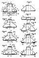
- FIG. 1 a cross-country ski 1 which has a cross section with an evolving profile in the longitudinal direction and which has, at its upper part, over most of its length, a longitudinal rib.
- the cross section of this rib, located above the edges of the ski, is made up, on certain parts of the length of the ski, by a single quadrilateral, in this case an isosceles trapezoid and, on another part of the length, by two superimposed quadrilaterals, in this case two isosceles trapezoids.
- the cross-country ski 1 can be subdivided into three longitudinal zones where the longitudinal rib is formed, namely a central zone A which bears a cross-country ski chase (not shown) which is connected to the ski at its front end and whose the sole is provided with a longitudinal groove, and two front longitudinal zones B and rear C which extend the central support zone A respectively towards the front and towards the rear, and which are connected to anterior and posterior end portions flat, that is to say devoid of the longitudinal rib.
- a central zone A which bears a cross-country ski chase (not shown) which is connected to the ski at its front end and whose the sole is provided with a longitudinal groove
- two front longitudinal zones B and rear C which extend the central support zone A respectively towards the front and towards the rear, and which are connected to anterior and posterior end portions flat, that is to say devoid of the longitudinal rib.
- the cross section of the rib of the cross-country ski 1 has the shape of a single isosceles trapezoid, while in the central longitudinal zone A its cross section consists of the superposition of two elementary sections, each has the shape of an isosceles trapezoid.
- FIG. 1 are represented various profiles of the cross section of the cross-country ski 1 along the length.
- At its extreme front cross-sectional part of the ski 1 1 has a flattened rectangular shape delimited laterally by the two vertical sides of the ski and 9.10 that is found all along the ski.
- the cross section of the rib considered to be limited to the part situated above the lower rectangular part delimited by the edges 9, 10 and which is absent in the anterior extreme part, has, in the anterior longitudinal zone B, the shape of a single isosceles trapezoid, of height going backwards, as it is represented by the two profiles 1b of small height and 1c of greater height than the previous one.
- a cross section of the rib 1 passes to the unique shape of an isosceles trapezium with the two superimposed isosceles trapezoids, as shown by profiles 1d and 1 e. Then the cross section of the rib again takes the form of a single isosceles trapezoid in the posterior section C, as illustrated by the profiles 1f, 1g, up to the extreme posterior part of the ski where the rib is absent and the cross section of the ski has a flattened rectangular shape similar to that of the anterior end portion.
- the cross section of the rib of the cross-country ski 1 comprises an upper elementary section 2, defining a longitudinal guide rib proper, and a lower elementary section or base 3, these two elementary sections each having, in this case, the shape of an isosceles trapezoid.
- the upper guide rib 2 has a horizontal upper face or edge 4 which is extended downwards by two inclined lateral faces 5,6.
- the three faces 4,5,6 define the upper rib 2 which contributes to the lateral guidance and to the centering of the boot on the ski, as a result of the engagement of this guide rib 2 in the longitudinal groove of the sole of the boot, during the practice of cross-country skiing.
- the inclination of the lateral faces 5, 6 of the upper guide rib 2, with respect to the vertical and longitudinal plane of symmetry P of the ski varies from the front to the rear of the central support zone A.
- the angle a formed by the inclined lateral faces 5, 6 with the vertical plane P varies from 0 to 10 degrees and is preferably close to 5 degrees, while in the rear part of the central support zone A, where the heel of the shoe applies, this angle is more important and it can vary from 20 to 40 degrees.
- the lower trapezoidal elementary section or base 3 comprises two inclined lateral faces 7,8 extending downwards the inclined lateral faces 5,6 and symmetrical with respect to the vertical plane P.
- the inclined lateral faces 7,8 of the base 3 are more inclined, with respect to the vertical and longitudinal plane P, than the upper inclined faces 5,6, the angle of inclination b of these faces 7,8 with respect to the plane P can vary from 30 to 60 degrees.
- the two lower inclined lateral faces 7,8 of the base 3 are connected to the vertical edges 9,10, of low height, of the ski.
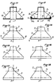
- FIGS 2 to 20 illustrate, by way of non-limiting examples, various embodiments of the cross-country ski according to the invention.
- cross-country skiing is achieved by assembling, by gluing, several profiles preferably made of a composite material of the glass-epoxy resin type.
- the cross-country ski is obtained by the assembly of two profiles, namely an external profile 11 or "shell", whose evolving cross section defines the profile of the ski over its whole length, as has been explained with reference to FIG. 1, and an internal profile 12 or "core” which retains the same shape of cross section over the entire length of the ski but whose height is variable.
- the ski also comprises a lower horizontal reinforcement element 13 which is glued under the core 12 and under this reinforcement element 13 is in turn glued the sole 14 of the ski itself.
- Figures 2 to 4 are shown various profiles of the shell 11 corresponding to that of the various cross sections of the ski. In FIG. 2 which represents a cross section of the ski in the central support zone A.
- the external shell 11 consequently has a cross section constituted by the two superimposed isosceles trapezoids and it comprises the upper horizontal face or edge 4, the faces upper 5.6 slightly inclined with respect to the vertical and longitudinal plane of symmetry P, and the lower lateral faces 7.8, more inclined with respect to the vertical plane P and which extend downwards by the vertical edges 9.10 of the ski .
- the inner core 12 has a cross section in the shape of an omega and it includes an upper horizontal wall 15, located under the edge 4 and glued to it, two side walls 16, 17, vertical or slightly inclined by with respect to the vertical and longitudinal plane P, by forming a rectangle or a central isosceles trapezoid, and two horizontal lower wings 18, extending outwards respectively from the lower ends of the vertical faces 16,17 and under which is glued the 'reinforcing element 13.
- These horizontal wings 18,19 may end with flanges 20,21 folded square upwards, parallel to the edges 9,10 and glued inside thereof.
- the distance between the lateral and vertical faces 16,17, at their lower ends where they are connected to the wings 18,19 is equal to one third of the width d of the ski, each of the wings 18.19 therefore also having a width equal to one third of the width of the ski d / 3.
- the advantage of such a distribution is that it makes it possible to obtain effective support for the upper guide rib, formed by the faces 4,5,6, to reinforce the "internal element or core 12" when it is pushed in. to reinforce the ski edges and to fulfill the shearing functions of a ski core while providing a hollow and light structure, having an excellent resistance / weight ratio.
- this core 12 transmits directly, by its lower part formed by the horizontal wings 18, 19, the forces exerted by the shoe on all parts of the ski in contact with snow, i.e. edges or edges 9.10.
- FIG. 3 represents the shape of the cross section of the ski in the anterior A or posterior zone B.
- the outer shell 11 has a cross section reduced to a single isosceles trapezium while the core 12, still in the form of an omega , has a reduced height.
- FIG. 4 represents the cross section of the ski in one of its anterior or posterior end portions.
- the outer shell 11 has a flat and horizontal shape and it covers the core 12, still in the form of an omega but of very reduced height.
- FIGS 5 to 7 illustrate various variants of the inner core of the ski.
- the inner core 22 has an I-shaped cross section whose upper horizontal wings 22a and lower 22b, connected by a vertical core 22c, are respectively glued in support under the edge 4 and on the central part of the reinforcing element 13.
- the cross section of the central core 23 has the shape of an inverted Y, and this core comprises an upper vertical core 23a extending to the middle a horizontal wing 23b glued under the edge 4, two inclined lower branches 23c, 23d coming from the vertical core 23a, extending downwards and outwards and which are connected to respective horizontal wings 23e, 23f extending outwards and glued to the reinforcing element 13.
- the cross section of the inner core is in the form of an omega and this core consists of two halves substantially symmetrical with respect to the plane P, each having substantially the shape of a Z.
- the upper horizontal wings 24a, 24b, extending towards the plane P, of these two Z-shaped halves are superimposed and glued to each other, under the edge 4, while the horizontal wings lower 24c and 24d, extending outwards, are glued to the reinforcing element 13.
- Vertical walls 24e, 24f extend respectively between the horizontal wings 24a, 24c on the one hand and 24b, 24d d ' somewhere else.
- FIG. 8 illustrates an alternative embodiment in which the reinforcing element 13 has, in its central part, a longitudinal rib 13a projecting inwards, this rib 13a extending between the lower parts of the two lateral faces and vertical 16,17 of the core 12 in the shape of an omega.
- FIG. 9 illustrates an embodiment in which each of the edges 9, 10 is extended inward by a rim with the respective square 9a, 10a held between the corresponding wing 18, 19 of the core 12 in the form of omega and the reinforcing element 13.
- the reinforcing element 13 is extended, at its ends, by a flange 13b extending at right angles upwards and which is kept glued between the flanges 20.21 of the wings 18.19 of the core 12 in the shape of an omega and the edges 9.10.
- FIG. 11 represents an alternative embodiment of a cross-country ski in which the edges 9, 10 practically no longer exist as such.
- the lower inclined lateral faces 7,8 are connected directly to the ends of the wings 18,19 of the core 12 and to the ends of the lower reinforcement element 13, the assembly being carried out as before by gluing.
- the lower horizontal wings 18, 19 of the omega-shaped core 12 end in flanges 22, 23 having in cross section the shape of an inverted U or open down.
- These U-shaped flanges 22,23 respectively cover the upwardly extending square edges 13b of the reinforcing element 13 and they are glued to both these edges 13b and to the edges 9,10 ski.
- FIG. 13 to 17 illustrate, without limitation, some profiles which can be adopted for the cross section of the ski, in the central area where the two superimposed quadrilaterals are located.
- FIG. 13 illustrates a cross section in which the upper elementary section 2 has a rectangular shape and is connected to the small upper base of a lower elementary section 3 in the form of an isosceles trapezoid, the assembly then being symmetrical with respect to the vertical plane and longitudinal P.
- the upper elementary section 2 has the shape of a rectangular trapezoid also connected to a lower elementary section 3 in the form of an isosceles trapezium.
- the upper elementary section 2 has the shape of any trapezium and it is connected to a lower elementary section 3 in the form of an isosceles trapezium.
- Figures 16,17,18 illustrate embodiments in which the elementary section 3 smaller than the shape of any trapezoid, the upper elementary section 2 having the shape of a rectangle or a square ( Figure 16 ), any trapezoid (Figure 17) or an isosceles trapezoid (Figure 18).
- Figures 19 and 20 illustrate embodiments of the invention in which the two upper elementary sections 2 and lower 3 are constituted by any quadrilaterals.
- the two quadrilaterals constituting the upper 2 and lower 3 elementary sections are connected along a common side, indicated in phantom, and which is contained in a junction plane P1 inclined relative to the horizontal.
- the lateral sides 5,6, converging upwards, of the quadrilaterals constituting the upper elementary section 2 are less inclined, with respect to the vertical and longitudinal plane P, than the lateral sides 7,8, convrerging upwards, of the quadrilateral constituting the lower elementary section 3.
- the upper side 4 of the upper elementary section 2 is horizontal, while in the embodiment of the invention shown in Figure 20, this side is inclined relative to the horizontal.
- FIG. 21 represents an alternative embodiment of the ski in which the central support zone A comprises a front part in which the cross section of the ski consists of two superimposed quadrilaterals, in this case two isosceles trapezoids, while its posterior part consists of a single quadrilateral, in this case an isosceles trapezium.
- the ski boot is guided at the front by the upper longitudinal rib engaging in a relatively narrow groove, formed in the front part of the shoe, while the heel of this shoe comes to bear on the rear part of the central zone A, with a cross section in the shape of a single isosceles trapezoid.
- the lower surface of the heel can then be flat, in which case the heel rests on the upper horizontal edge 4 of the rib, or else it can have a longitudinal notch so that this notch comes to cover the rib.
- the interior of the ski can be left empty or it can be filled with an appropriate filling material.
- the upper longitudinal rib 2 of the ski has a width and / or height which is constant, as shown in the drawing, or variable along its length. It can be used not only for lateral guidance and centering of the shoe but also for mounting the binding holding the front end of the shoe.
Landscapes
- Footwear And Its Accessory, Manufacturing Method And Apparatuses (AREA)
- Farming Of Fish And Shellfish (AREA)
- Transplanting Machines (AREA)
- Gyroscopes (AREA)
- Organic Low-Molecular-Weight Compounds And Preparation Thereof (AREA)
- Acyclic And Carbocyclic Compounds In Medicinal Compositions (AREA)
- Semiconductor Lasers (AREA)
Claims (25)
- Ski mit einem der Sohle eines Schuhs als Auflage dienenden Mittelabschnitt (A), der zwischen zwei Längsabschnitten, nämlich einem vorderen Längsabschnitt (B) und einem hinteren Längsabschnitt (C) angeordnet ist, die den Mittelabschnitt nach vorn bzw. nach hinten verlängern und die mit den vorderen und hinteren ebenen Endabschnitten des Skis bündig sind, und mit einer oberen, in Längsrichtung verlaufenden Rippe, die sich über den größeren Teil der Länge des Skis bis zu seinen ebenen Enden erstreckt, dadurch gekennzeichnet, daß der Querschnitt der Rippe im Mittelabschnitt (A) durch die Überlagerung wenigstens zweier Elementarquerschnitte (2, 3) gebildet wird, deren jeder einen viereckigen Querschnitt bildet und die sich an einer gemeinsamen Seite aneinander anschließen, die die Unterseite des oberen Elementarquerschnitts und die Oberseite dem unteren Elementarquerschnitts ist, dessen Unterseite horizontal ist, wobei die Seitenflächen (7, 8) des unteren Elementarabschnitts (3) nach oben konvergieren und in Bezug auf eine vertikale Längsebene (P) mehr geneigt sind als die Seitenflächen (5, 6) des oberen Elementarquerschnitts (2), und daß im voderen Abschnitt (B) und im hinteren Abschnitt (C) der Querschnitt der Rippe die Form nur eines einzigen Vierecks aufweist.
- Ski nach Anspruch 1, dadurch gekennzeichnet, daß die Seitenflächen (5, 6) des oberen Elementarquerschnitts 2) nach oben konvergieren.
- Ski nach Anspruch 1, dadurch gekennzeichnet, daß die Seitenflächen (5, 6) des oberen Elementarquerschnitts (2) vertikal verlaufen.
- Ski nach einem der vorhergehenden Ansprüche, dadurch gekennzeichnet, daß die Auflagezone (A) der Schuhsohle eine Länge aufweist, die gleich der des Schuhs oder größer ist.
- Ski nach einem der vorhergehenden Ansprüche, dadurch gekennzeichnet, daß er durch die Verbindung zweier Profile erhalten wird, nämlich eines äußeren Profils (11) oder einer "Schale", dessen sich verändernder Querschnitt das Profil des Skis über seine Länge bestimmt, und eines inneren Profils (12) oder eines "Kerns", der über die ganze Länge des Skis die gleiche Querschnittsform beibehält, aber dessen Höhe veränderlich ist.
- Ski nach Anspruch 5, dadurch gekennzeichnet, daß er ein horizontales unteres Verstärkungselement (13) aufweist, das unter den Kern (12) geklebt ist, und daß unter dieses Verstärkungselement (13) seinerseite die eigentliche Sohle (14) des Skis geklebt ist.
- Ski nach einem der Ansprüche 5 oder 6, dadurch gekennzeichnet, daß der Kern (12, 22, 23, 24) eine horizontale obere Wand (15, 22a, 232b, 24a) aufweist, die unter die darüber befindliche horizontale fläche oder Kante (4) der äußeren Schale (11) geklebt ist, wenigstens eine horizontale Wand (18, 19; 22b; 23e; 23f; 24c, 24b) die mit den unteren horizontalen Verstärkungselemehnt ( 13) verklebt ist, und wenigstens eine vertikale Wand (16, 17; 22c; 23a; 24e, 24f), die sich zwischen der oberen und der unteren horizontalen Wand erstreckt.
- Ski nach Anspruch 7, dadurch gekennzeichnet, daß der innere Kern (12) einen Querschnitt in Omegaform aufweist und eine obere horizontale Wand (15) besitzt, die unter der Kante (4) angeordnet und mit dieser verklebt ist, sowie zwei vertikale oder in Bezug auf die vertikale Längsebene (P) schwach geneigte Seitenwände (16, 17), die ein zentrales Rechteck oder gleichschenkliges Trapez bilden, und zwei untere, horizontale Flügel (18), die sich von den unteren Enden der vertikalen Seitenflächen (16, 17) aus nach außen erstrecken und unter welche das Verstärkungselement (13) geklebt ist.
- Ski nach Anspruch 7, dadurch gekennzeichnet, daß der innere Kern (22) einen Querschnitt in Form eines I aufweist, dessen obere (22a) und untere (22b), durch einen Steg (22c) verbundene horizontale Abschnitte unter der Kante (4) an diese bzw. auf den zentralen Abschnitt des Verstärkungselements (13) geklebt sind.
- Ski nach Anspruch 7, dadurch gekennzeichnet, daß der Querschnitt des zentralen Kerns (23) die Form eines umgekehrten Y aufweist und daß dieser Kern einen vertkalen oberen Steg (23a) besitzt, der sich bis in die Mitte eines horizontalen Flügels (23b) erstreckt, der unter die Kante (4) geklebt ist, sowie zwei vom vertikalen Steg (23a) ausgehende, untere, geneigte Arme (23c, 23d), die sich nach unten und außen ertrecken und sich an die nach außen gerichteten und mit dem Verstärkungelement verklebten, horizontalen, Flügel (23e bzw. 23f) anschließen.
- Ski nach Anspruch 7, dadurch gekennzeichnet, daß der Querschnitt des inneren Kerns Omegaform aufweist und von zwei im wesentlichen in Bezug auf die Ebene P symmetrisch angeordneten Hälften gebildet wird, deren jede im wesentlichen Z-förmig ist, wobei die horizontalen oberen Abschnitte (24a, 24b) der beiden Z-förmigen Hälften sich in Richtung auf die Ebene (P) erstrecken und übereinandergelegt und miteinander unter der Kante (4) verklebt sind, während die unteren horizontalen, sich nach außen erstreckenden Abschnitte (24c, 24d) mit dem Verstärkungselement (13) verklebt sind und sich die horizontalen Stege (24e, 24f) zwischen den horizontalen Abschnitten (24a, 24c) einerseits und (24b, 24d) andererseits erstrecken.
- Ski nach einem der Ansprüche 5 bis 11, dadurch gekennzeichnet, daß das Verstärkungselement (13) in seinem mittleren Abschnitt eine nach innen vorspringende Längsrippe (13a) aufweist.
- Ski nach einem der Ansprüche 7 bis 12, dadurch gekennzeichnet, daß die geneigten unteren Seitenflächen (7, 8) der äußeren Schale (11) sich nach unten durch vertikale Kanten (9, 10) verlängern, an deren Innenseite sich die vertikalen Ränder (20, 21; 22, 23; 13b) des Kerns (12) oder des horizontalen, unteren Verstärkungselements (13) erstrecken und angeklebt sind.
- Ski nach Anspruch 13, dadurch gekennzeichnet, der innere, im Querschnitt die Form eines Omega aufweisende Kern (12) zwei horizontale untere Flügel (18, 19) aufweist, die sich nach außen erstrecken und in sich vertikal nach oben erstreckenden Rändern (20, 21) enden.
- Ski nach Anspruch 14, dadurch gekennzeichnet, daß die vertikalen Ränder (20, 21) der horizontalen unteren Flügel (18, 19) des Kerns (12) direkt mit den Kanten (9, 10) der äußeren Schale (11) verklebt sind.
- Ski nach nach Anspruch 15, dadurch gekennzeichnet, daß das untere Verstärkungselement (13) in sich nach oben erstreckenden Rändern (13b) endet, die zwischen die vertikalen Kanten (9. 10) und die Vertikalen Ränder (20, 21 22, 23) der Flügel (18, 19) des Kerns (12) eingreifen und mit diesen durch Kleben verbunden sind.
- Ski nach Anspruch 16, dadurch gekennzeichnet, daß die Ränder (22, 23) der Flügel (18, 19) des Kerns (12) eine umgekehrte U-Form aufweisen, derart, daß sie die vertikalen Ränder (13b) des Verstärkungselements (13) umschließen.
- Ski nach einem der Ansprüche 7 bis 12, dadurch gekennzeichnet, daß die geneigten unteren Seitenflächen (7, 8) der äußeren Schale sich direkt an die Enden des unteren Verstärkungselements (13) anschließen.
- Ski nach einem der vorhergehenden Ansprüche, dadurch gekennzeichnet, daß der untere Elementarquerschnitt (3) die Form eines beliebigen, insbesondere gleichschenkligen Trapezes aufweist und der obere Elementarquerschnitt (2) die Form eines rechtwinkligen oder trapezartigen Vierecks.
- Ski nach Anspruch 19, dadurch gekennzeichnet, daß die beiden Elementarquerschnitte (2, 3) jeweils die Form eines gleichschenkligen Trapezes aufweisen und aneinander mit einer gemeinsamen Basis angrenzen, die die große Basis des oberen trapezförmigen Elementarquerschnitts (2) und die kleine Basis des unteren (trapezförmigen Elementarquerschnitts (3) bildet.
- Ski nach Anspruch 20, dadurch gekennzeichnet, daß daß der eine obere Führungsrippe bildende, obere trapezförmige Elementarquerschnitt (2) eine obere horizontale Fläche oder Kante (4) aufweist, die nach unten durch zwei geneigte und in Bezug auf die vertikal und längs verlaufende Symmetrieebene (P) des Ski symmetrische Seitenflächen (5, 6) vrlängert ist, und daß der trapezförmige untere Elementarquerschnitt (3) zwei geneigte Seitenflächen (7,8) aufweist, die die geneigten und zur vertikalen Ebene (P) symmetrischen Seitenflächen (5, 6) nach unten verlängern, und daß die geneigten unteren Seitenflächen (7. 8) der Basis (3) in Bezug auf die vertikale Längsebene (P) mehr geneigt sind als die oberen geneigten Flächen (5, 6).
- Ski nach Anspruch 21, dadurch gekennzeichnet, daß der Neigungswinkel der Seitenflächen (5, 6) der oberen Führungsrippe (2) in Bezug auf die vertikal und längs verlaufende Symmetrieebene (P) des Ski sich vor und hinter dem mittleren Auflagebereich verändert.
- Ski nach Anspruch 22, dadurch gekennzeichnet, daß sich vor dem mittleren Auflagebereich (A), in dem das untere Ende des Schuhs befestigt wird, der Winkel a, den die geneigten Seitenflächen (5, 6) mit der Vertikalebene (P) einschließen, von 0 bis 10 Grad verändert und vorzugsweise bei 5 Grad liegt, während im Bereich hinter dem mittleren Auflagebereich (A) dieser Winkel größer ist und sich zwischen 20 und 40 Grad verändern kann.
- Ski nach einem der Ansprüche 22 und 23, dadurch gekennzeichnet, daß der Neigungswinkel (b) der unteren geneigten Seitenflächen (7, 8) der Basis (3) in Bezug auf die vertikale Längsebene (p) sich zwischen 30 und 60 Grad verändert.
- Ski nach einem der Ansprüche 1 bis 17, dadurch gekennzeichnet, daß die oberen (2) und unteren (3) Elementarquerschnitte jeweils die Form eines beliebigen Vierecks aufweisen.
Priority Applications (1)
| Application Number | Priority Date | Filing Date | Title |
|---|---|---|---|
| AT88400256T ATE76319T1 (de) | 1987-02-05 | 1988-02-04 | Ski mit einer laengsseitigen oberen rippe. |
Applications Claiming Priority (2)
| Application Number | Priority Date | Filing Date | Title |
|---|---|---|---|
| FR878701420A FR2610526B1 (fr) | 1987-02-05 | 1987-02-05 | Ski de fond comportant une nervure longitudinale en saillie par rapport a sa face superieure |
| FR8701420 | 1987-02-05 |
Publications (2)
| Publication Number | Publication Date |
|---|---|
| EP0283331A1 EP0283331A1 (de) | 1988-09-21 |
| EP0283331B1 true EP0283331B1 (de) | 1992-05-20 |
Family
ID=9347627
Family Applications (2)
| Application Number | Title | Priority Date | Filing Date |
|---|---|---|---|
| EP88400257A Expired - Lifetime EP0278859B1 (de) | 1987-02-05 | 1988-02-04 | Langlaufski |
| EP88400256A Expired - Lifetime EP0283331B1 (de) | 1987-02-05 | 1988-02-04 | Ski mit einer längsseitigen oberen Rippe |
Family Applications Before (1)
| Application Number | Title | Priority Date | Filing Date |
|---|---|---|---|
| EP88400257A Expired - Lifetime EP0278859B1 (de) | 1987-02-05 | 1988-02-04 | Langlaufski |
Country Status (8)
| Country | Link |
|---|---|
| US (2) | US4957304A (de) |
| EP (2) | EP0278859B1 (de) |
| AT (2) | ATE65030T1 (de) |
| DE (2) | DE3871199D1 (de) |
| FI (2) | FI884576L (de) |
| FR (1) | FR2610526B1 (de) |
| NO (1) | NO164881C (de) |
| WO (2) | WO1988005676A1 (de) |
Families Citing this family (20)
| Publication number | Priority date | Publication date | Assignee | Title |
|---|---|---|---|---|
| FR2634131B1 (fr) * | 1988-07-13 | 1990-04-27 | Salomon Sa | Chaussure et semelle notamment pour ski de fond |
| AT394811B (de) * | 1988-09-23 | 1992-06-25 | Head Sportgeraete Gmbh | Ski |
| US5249819A (en) * | 1988-09-23 | 1993-10-05 | Head Sportgerate Gesellschaft M.B.H. & Co., Ohg | Ski having a hollow body of uniform width |
| FR2638976B1 (fr) * | 1988-11-14 | 1991-02-08 | Salomon Sa | Dispositif de guidage lateral d'une chaussure de ski fixee, a son extremite avant, sur un ski tel qu'un ski de fond |
| FR2652509B1 (fr) * | 1989-10-04 | 1991-12-20 | Salomon Sa | Arete de guidage d'une chaussure de ski de fond. |
| FR2659025B1 (fr) * | 1990-03-02 | 1992-05-15 | Salomon Sa | Dispositif de rappel d'une chaussure de ski sur un ski. |
| FR2660569B1 (fr) * | 1990-04-06 | 1993-07-09 | Salomon Sa | Fixation pour ski de fond. |
| AT397210B (de) * | 1990-04-12 | 1994-02-25 | Kaestle Ag | Ski mit skibindung |
| FR2668709A1 (fr) * | 1990-11-06 | 1992-05-07 | Salomon Sa | Dispositif de guidage lateral d'une chaussure sur un ski de fond. |
| FR2672505B1 (fr) * | 1991-02-08 | 1993-05-21 | Salomon Sa | Ski pour sport d'hiver comprenant une plateforme de montage des fixations. |
| AT400676B (de) * | 1991-02-22 | 1996-02-26 | Head Sport Ag | Ski |
| FR2705248B1 (fr) * | 1993-05-14 | 1995-07-28 | Salomon Sa | Dispositif de retenue d'une chaussure sur une planche de glisse. |
| FR2705905B1 (fr) * | 1993-06-02 | 1995-07-07 | Rossignol Sa | Ski à profil perfectionné. |
| FR2718651B1 (fr) * | 1994-04-15 | 1996-06-14 | Rossignol Sa | Ski alpin. |
| AT405137B (de) * | 1995-02-07 | 1999-05-25 | Fischer Gmbh | Langlaufski |
| FR2834906B1 (fr) * | 2002-01-24 | 2004-04-02 | Rossignol Sa | Perfectionnement pour planche de glisse sur neige |
| US6857653B2 (en) * | 2002-10-31 | 2005-02-22 | Anton F. Wilson | Gliding skis |
| FR2848868B1 (fr) * | 2002-12-19 | 2007-01-19 | Salomon Sa | Planche de glisse ou de roulage |
| US7073810B2 (en) * | 2003-06-25 | 2006-07-11 | Wilson Anton F | Ski with tunnel and enhanced edges |
| FR2859110B1 (fr) * | 2003-09-03 | 2006-04-07 | Salomon Sa | Systeme de ski de fond avec surface laterale d'appui direct |
Family Cites Families (19)
| Publication number | Priority date | Publication date | Assignee | Title |
|---|---|---|---|---|
| CH68226A (fr) * | 1913-07-09 | 1915-03-01 | Michel Abrard Edouard Felix | Changement de vitesse |
| CH152918A (de) * | 1931-02-28 | 1932-02-29 | Aluminium Ind Ag | Ski aus Leichtmetall-Legierung und Verfahren zur Herstellung desselben. |
| DE682623C (de) * | 1938-07-21 | 1939-10-19 | Ludwig Zedelmayer | Mehrschichtenholzski |
| CH248512A (fr) * | 1945-11-02 | 1947-05-15 | Authier John | Ski. |
| FR1282053A (fr) * | 1960-12-06 | 1962-01-19 | Skis composites | |
| FR84816E (fr) * | 1963-10-09 | 1965-04-23 | Ski | |
| FR92020E (fr) * | 1967-03-17 | 1968-09-13 | Plastiques Synthetiques | Ski perfectionné |
| DE2033845A1 (de) * | 1970-07-01 | 1972-01-20 | ||
| US4094528A (en) * | 1976-10-21 | 1978-06-13 | John Michael Cluzel | Ski structure |
| DE2826884A1 (de) * | 1978-06-19 | 1979-12-20 | Anton Plenk | Ski |
| FR2447209A1 (fr) * | 1979-01-26 | 1980-08-22 | Salomon & Fils F | Ensemble de fixation d'une chaussure a un ski |
| FR2483240A1 (fr) * | 1980-06-02 | 1981-12-04 | Salomon & Fils F | Dispositif de recentrage et de retenue laterale d'une chaussure sur un ski de fond ou de randonnee |
| IT8253045U1 (it) * | 1982-03-11 | 1983-09-11 | Tua Ski Srl | Sci per nevi profonde e difficili |
| CA1259084A (fr) * | 1984-05-29 | 1989-09-05 | Pierre Corbet | Ski de fond avec son systeme de fixation de la chaussure |
| FR2565117B1 (fr) * | 1984-06-04 | 1987-10-09 | Salomon Sa | Dispositif de guidage d'une chaussure de ski, et chaussure et ski de fond adaptes a ce dispositif |
| FR2572944B1 (fr) * | 1984-11-15 | 1987-02-27 | Salomon Sa | Dispositif de guidage lateral d'une chaussure de ski, fixee a son extremite avant, sur un ski de fond |
| AT383496B (de) * | 1985-02-25 | 1987-07-10 | Head Sportgeraete Gmbh | Ski |
| FR2590131B1 (fr) * | 1985-11-15 | 1988-06-24 | Salomon Sa | Dispositif de guidage lateral et d'appui d'une chaussure fixee, a son extremite avant, sur un ski de fond |
| FR2610525A1 (fr) * | 1987-02-05 | 1988-08-12 | Salomon Sa | Ski de fond presentant une nervure longitudinale en saillie par rapport a sa face superieure |
-
1987
- 1987-02-05 FR FR878701420A patent/FR2610526B1/fr not_active Expired
-
1988
- 1988-02-04 WO PCT/FR1988/000061 patent/WO1988005676A1/fr not_active Ceased
- 1988-02-04 FI FI884576A patent/FI884576L/fi not_active IP Right Cessation
- 1988-02-04 DE DE8888400256T patent/DE3871199D1/de not_active Expired - Fee Related
- 1988-02-04 WO PCT/FR1988/000060 patent/WO1988005675A1/fr not_active Ceased
- 1988-02-04 DE DE8888400257T patent/DE3863552D1/de not_active Expired - Fee Related
- 1988-02-04 AT AT88400257T patent/ATE65030T1/de not_active IP Right Cessation
- 1988-02-04 EP EP88400257A patent/EP0278859B1/de not_active Expired - Lifetime
- 1988-02-04 EP EP88400256A patent/EP0283331B1/de not_active Expired - Lifetime
- 1988-02-04 AT AT88400256T patent/ATE76319T1/de not_active IP Right Cessation
- 1988-02-04 US US07/275,131 patent/US4957304A/en not_active Expired - Fee Related
- 1988-02-04 US US07/275,138 patent/US5064214A/en not_active Expired - Lifetime
- 1988-09-30 NO NO884357A patent/NO164881C/no unknown
- 1988-10-05 FI FI884577A patent/FI884577A7/fi not_active Application Discontinuation
Also Published As
| Publication number | Publication date |
|---|---|
| WO1988005676A1 (fr) | 1988-08-11 |
| FI884576A0 (fi) | 1988-10-05 |
| DE3871199D1 (de) | 1992-06-25 |
| EP0283331A1 (de) | 1988-09-21 |
| FI884576A7 (fi) | 1988-10-05 |
| US4957304A (en) | 1990-09-18 |
| US5064214A (en) | 1991-11-12 |
| NO164881B (no) | 1990-08-20 |
| FR2610526A1 (fr) | 1988-08-12 |
| EP0278859B1 (de) | 1991-07-10 |
| FR2610526B1 (fr) | 1989-12-01 |
| FI884576L (fi) | 1988-10-05 |
| ATE76319T1 (de) | 1992-06-15 |
| ATE65030T1 (de) | 1991-07-15 |
| FI884577A0 (fi) | 1988-10-05 |
| NO884357L (no) | 1988-11-29 |
| DE3863552D1 (de) | 1991-08-14 |
| EP0278859A1 (de) | 1988-08-17 |
| NO884357D0 (no) | 1988-09-30 |
| WO1988005675A1 (fr) | 1988-08-11 |
| FI884577A7 (fi) | 1988-10-05 |
| NO164881C (no) | 1990-11-28 |
Similar Documents
| Publication | Publication Date | Title |
|---|---|---|
| EP0283331B1 (de) | Ski mit einer längsseitigen oberen Rippe | |
| EP0543743B1 (de) | Ski mit nicht rechteckigem Schnitt | |
| EP0577947B1 (de) | Ski mit einer Rippe und einer Stützvorrichtung | |
| CA1270268A (fr) | Dispositif de guidage d'une chaussure de ski, et chaussure et ski de fond adaptes a ce dispositif | |
| EP0620027B1 (de) | Ski mit Seitenwangen und Oberschale | |
| CA1328891C (fr) | Dispositif de guidage lateral d'une chaussure de ski fixee, a son extremite avant, sur un ski tel qu'un ski de fond | |
| FR2463589A1 (fr) | Chaussure de ski de fond | |
| FR2610525A1 (fr) | Ski de fond presentant une nervure longitudinale en saillie par rapport a sa face superieure | |
| FR2572944A1 (fr) | Dispositif de guidage lateral d'une chaussure de ski, fixee a son extremite avant, sur un ski de fond | |
| EP1616602B1 (de) | Zusatzelement für die Oberseite von Schneegleitbretter | |
| FR2832643A1 (fr) | Perfectionnement pour planche de glisse sur neige | |
| FR2598931A1 (fr) | Ski profile a dissymetrie variable | |
| CA2209772A1 (fr) | Chaussure de sport | |
| FR2651145A1 (fr) | Fixation de securite pour ski. | |
| EP0619127B1 (de) | Ski | |
| EP1424108B1 (de) | Schneegleitbrett mit seitliche Abstützungplatte | |
| FR2644705A1 (fr) | Procede de fabrication d'un ski et ski obtenu par un tel procede | |
| EP0765679B1 (de) | Langlaufski, insbesondere geeignet für das Üben des Skatings | |
| FR2610527A1 (fr) | Ski de fond comportant une nervure longitudinale en saillie par rapport a sa face superieure | |
| FR2747579A1 (fr) | Procede de realisation d'une planche de glisse et planche de glisse obtenue par ce procede | |
| FR2715077A1 (fr) | Ski, ou autre planche de glisse sur neige, équipé de carres métalliques qui comportent des ailettes d'ancrage. | |
| FR2720288A1 (fr) | Ski dont la section varie sur la longueur. | |
| BE894876A (fr) | Chassis de toiture en profils metalliques notamment pour serre ou veranda | |
| FR2643564A1 (fr) | Ski a section transversale ayant, au moins dans sa partie centrale, sensiblement la forme d'un trapeze isocele | |
| FR2778340A1 (fr) | Fixation d'une toile de raquette a neige et son procede de fabrication |
Legal Events
| Date | Code | Title | Description |
|---|---|---|---|
| PUAI | Public reference made under article 153(3) epc to a published international application that has entered the european phase |
Free format text: ORIGINAL CODE: 0009012 |
|
| AK | Designated contracting states |
Kind code of ref document: A1 Designated state(s): AT CH DE FR IT LI SE |
|
| 17P | Request for examination filed |
Effective date: 19890206 |
|
| 17Q | First examination report despatched |
Effective date: 19900320 |
|
| GRAA | (expected) grant |
Free format text: ORIGINAL CODE: 0009210 |
|
| AK | Designated contracting states |
Kind code of ref document: B1 Designated state(s): AT CH DE FR IT LI SE |
|
| PG25 | Lapsed in a contracting state [announced via postgrant information from national office to epo] |
Ref country code: IT Free format text: LAPSE BECAUSE OF FAILURE TO SUBMIT A TRANSLATION OF THE DESCRIPTION OR TO PAY THE FEE WITHIN THE PRESCRIBED TIME-LIMIT;WARNING: LAPSES OF ITALIAN PATENTS WITH EFFECTIVE DATE BEFORE 2007 MAY HAVE OCCURRED AT ANY TIME BEFORE 2007. THE CORRECT EFFECTIVE DATE MAY BE DIFFERENT FROM THE ONE RECORDED. Effective date: 19920520 Ref country code: AT Effective date: 19920520 |
|
| REF | Corresponds to: |
Ref document number: 76319 Country of ref document: AT Date of ref document: 19920615 Kind code of ref document: T |
|
| REF | Corresponds to: |
Ref document number: 3871199 Country of ref document: DE Date of ref document: 19920625 |
|
| PG25 | Lapsed in a contracting state [announced via postgrant information from national office to epo] |
Ref country code: CH Effective date: 19930228 Ref country code: LI Effective date: 19930228 |
|
| PLBE | No opposition filed within time limit |
Free format text: ORIGINAL CODE: 0009261 |
|
| STAA | Information on the status of an ep patent application or granted ep patent |
Free format text: STATUS: NO OPPOSITION FILED WITHIN TIME LIMIT |
|
| 26N | No opposition filed | ||
| REG | Reference to a national code |
Ref country code: CH Ref legal event code: PL |
|
| EAL | Se: european patent in force in sweden |
Ref document number: 88400256.9 |
|
| PGFP | Annual fee paid to national office [announced via postgrant information from national office to epo] |
Ref country code: DE Payment date: 19960112 Year of fee payment: 9 |
|
| PGFP | Annual fee paid to national office [announced via postgrant information from national office to epo] |
Ref country code: SE Payment date: 19960125 Year of fee payment: 9 |
|
| PGFP | Annual fee paid to national office [announced via postgrant information from national office to epo] |
Ref country code: FR Payment date: 19960130 Year of fee payment: 9 |
|
| PG25 | Lapsed in a contracting state [announced via postgrant information from national office to epo] |
Ref country code: SE Effective date: 19970205 |
|
| PG25 | Lapsed in a contracting state [announced via postgrant information from national office to epo] |
Ref country code: FR Effective date: 19971030 |
|
| PG25 | Lapsed in a contracting state [announced via postgrant information from national office to epo] |
Ref country code: DE Effective date: 19971101 |
|
| EUG | Se: european patent has lapsed |
Ref document number: 88400256.9 |
|
| REG | Reference to a national code |
Ref country code: FR Ref legal event code: ST |