EP0283342A1 - Walzgerüst mit axial verschiebbaren Walzen und Verfahren zum Steuern des Walzenprofils - Google Patents
Walzgerüst mit axial verschiebbaren Walzen und Verfahren zum Steuern des Walzenprofils Download PDFInfo
- Publication number
- EP0283342A1 EP0283342A1 EP88400372A EP88400372A EP0283342A1 EP 0283342 A1 EP0283342 A1 EP 0283342A1 EP 88400372 A EP88400372 A EP 88400372A EP 88400372 A EP88400372 A EP 88400372A EP 0283342 A1 EP0283342 A1 EP 0283342A1
- Authority
- EP
- European Patent Office
- Prior art keywords
- cylinders
- plane
- cylinder
- support
- bending
- Prior art date
- Legal status (The legal status is an assumption and is not a legal conclusion. Google has not performed a legal analysis and makes no representation as to the accuracy of the status listed.)
- Granted
Links
- 238000005096 rolling process Methods 0.000 title claims abstract description 54
- 238000000034 method Methods 0.000 title claims description 5
- 238000005452 bending Methods 0.000 claims description 50
- 238000006073 displacement reaction Methods 0.000 claims description 35
- 238000003754 machining Methods 0.000 claims description 18
- 230000000694 effects Effects 0.000 claims description 9
- 230000000712 assembly Effects 0.000 claims description 8
- 238000000429 assembly Methods 0.000 claims description 8
- 239000012530 fluid Substances 0.000 claims description 5
- 238000004364 calculation method Methods 0.000 claims description 4
- 238000006243 chemical reaction Methods 0.000 claims description 4
- 230000000284 resting effect Effects 0.000 claims description 4
- 238000012937 correction Methods 0.000 claims description 3
- 238000009826 distribution Methods 0.000 claims description 2
- 230000002706 hydrostatic effect Effects 0.000 claims 1
- 238000005192 partition Methods 0.000 description 4
- 210000005069 ears Anatomy 0.000 description 3
- 238000010586 diagram Methods 0.000 description 1
- 238000005516 engineering process Methods 0.000 description 1
- 238000012423 maintenance Methods 0.000 description 1
- 238000004519 manufacturing process Methods 0.000 description 1
- 230000002093 peripheral effect Effects 0.000 description 1
- 230000001681 protective effect Effects 0.000 description 1
Images


Classifications
-
- B—PERFORMING OPERATIONS; TRANSPORTING
- B21—MECHANICAL METAL-WORKING WITHOUT ESSENTIALLY REMOVING MATERIAL; PUNCHING METAL
- B21B—ROLLING OF METAL
- B21B31/00—Rolling stand structures; Mounting, adjusting, or interchanging rolls, roll mountings, or stand frames
- B21B31/16—Adjusting or positioning rolls
- B21B31/18—Adjusting or positioning rolls by moving rolls axially
-
- B—PERFORMING OPERATIONS; TRANSPORTING
- B21—MECHANICAL METAL-WORKING WITHOUT ESSENTIALLY REMOVING MATERIAL; PUNCHING METAL
- B21B—ROLLING OF METAL
- B21B29/00—Counter-pressure devices acting on rolls to inhibit deflection of same under load, e.g. backing rolls ; Roll bending devices, e.g. hydraulic actuators acting on roll shaft ends
-
- B—PERFORMING OPERATIONS; TRANSPORTING
- B21—MECHANICAL METAL-WORKING WITHOUT ESSENTIALLY REMOVING MATERIAL; PUNCHING METAL
- B21B—ROLLING OF METAL
- B21B13/00—Metal-rolling stands, i.e. an assembly composed of a stand frame, rolls, and accessories
- B21B13/001—Convertible or tiltable stands, e.g. from duo to universal stands, from horizontal to vertical stands
-
- B—PERFORMING OPERATIONS; TRANSPORTING
- B21—MECHANICAL METAL-WORKING WITHOUT ESSENTIALLY REMOVING MATERIAL; PUNCHING METAL
- B21B—ROLLING OF METAL
- B21B31/00—Rolling stand structures; Mounting, adjusting, or interchanging rolls, roll mountings, or stand frames
- B21B31/16—Adjusting or positioning rolls
- B21B31/20—Adjusting or positioning rolls by moving rolls perpendicularly to roll axis
- B21B31/203—Balancing rolls
Definitions
- the subject of the invention is a rolling mill with axially displaceable rollers and also covers a method of adjusting the profile and distributing wear of the rolls in such a rolling mill.
- a rolling mill comprises, inside a support cage, at least two working rolls resting, in a clamping plane, on at least two support rolls.
- the cylinders are carried at their two ends by means of bearings, in chocks mounted mobile, parallel to the clamping plane, in windows provided on each upright of the support cage, each chock being provided with two lateral guide faces. sliding along corresponding sliding faces formed on the amount of the cage on either side of the chock.
- a bending or bending of the working rolls and possibly of the rolls is carried out.
- the bending device consists, for each chock, of two sets of jacks placed symmetrically on either side of the chock.
- each support part of the chock rests on two cylinders spaced axially symmetrically on either side of the median plane of the chock bearings so that the bending force is well distributed on the bearings.
- the rolling mill stand is symmetrical with respect to a median plane perpendicular to the clamping plane and which corresponds to the median plane of the rolled product. Normally the cylinders are therefore centered on this plane with respect to which the chocks are arranged symmetrically.
- the bending of the working rolls also ensures a balancing effect between the rolls which it is useful to maintain during the axial adjustment even when the rolling force is eliminated.
- the subject of the invention is a device allowing axial displacement of the cylinders without ceasing to exert the bending effort.
- the invention relates to a new device making it possible to carry out at the same time the bending and the axial displacement of the working rolls or of the intermediate rolls without appreciably modifying the constitution of the rolling mill.
- the invention makes it possible in particular to avoid the high friction between guide surfaces liable to disturb the vertical adjustment movements of the chocks.
- the invention therefore applies to a rolling mill with axially displaceable rollers comprising, inside a support cage at least two working rolls resting on a clamping plane P1, on at least two support rolls and the ends of which are carried, by means of bearings in chocks slidably mounted in the support cage, at least one of the working cylinders being associated, on the one hand, with means for moving said cylinder along its axis on either side of a position for centering the working cylinders on the median plane P2 of the cage, and on the other hand means for bending said cylinder comprising, for each chock two symmetrical assemblies of at least two cambering cylinders spaced apart from one another in the axial direction, and acting respectively on support parts provided on each side of the chock, said sets of cylinders being placed inside a block of support secured to the cage.
- each set of cambering cylinders is supported in the direction of the cambering force on a sliding part mounted to slide vertically between two pairs of guide faces formed in a machining carried out inside the block of support and respectively parallel and perpendicular to the rolling plane P1 and the corresponding support part of the chock rests with the possibility of sliding on a flat and smooth face formed on said sliding part on the side opposite to the camber cylinder.
- the bending effort is exerted by means of fixed jacks bearing on each end, on one side on the support block secured to the cage and on the other on a part on which the chock can slide. during axial displacements, this part being slidably mounted on the support block in the direction of application of the bending force and associated with embedding means making it possible to resist the effects of overturning in the direction of the axial displacement of the cylinders .
- the sliding part comprises support parts in the cambering direction of each cambering cylinder, extending horizontally above each cylinder and at least one part in the form of a guide foot s extending vertically by engaging between two spaced apart sides of the sliding guide of said foot, perpendicular to the rolling plane and formed on two opposite faces of the machining carried out inside the support block 5.
- each cambering assembly comprises two jacks spaced from each other and centered in a plane parallel to the rolling plane
- the sliding part has the shape of a T having a central internal part forming the guide leg extending vertically between the two cylinders inside the support block and an outer part forming two wings extending horizontally on either side of the guide leg, each above one said jacks.
- the guidance thus produced makes it possible to resist the overturning forces resulting from the offset of the support parts of the chock with respect to the sliding part during axial displacements and, taking into account the length of the guide foot, the latter s 'performs with low friction and does not penalize vertical movements.
- the sliding part is slidably mounted between two guide faces parallel to the rolling plane and formed in a second machining carried out inside the support block and extending outward the internal machining in which engages the guide foot.
- these two guide faces parallel to the rolling plane are symmetrically spaced apart on either side of the plane passing through the axes of the cambering cylinders and the support part of the chock is itself centered in the same plane in which thus pass all the forces applied by the bending.
- the machining carried out in the support block comprises an enlarged external part passing above the two cambering cylinders in which is guided the external part of the sliding part 7 in the shape of a T on which rests on one side the chock and on the other the camber cylinders and an internal part forming a central well in which the foot of the guide of the sliding part.
- the embedding effect of the guide foot makes it possible at the same time to carry out the axial displacement and the camber of the working rolls by opposing the moment of overturning which results from the offset of the median plane of the bearing by relation to the plane of symmetry of the two pairs of camber cylinders.
- this offset becomes too large, it results in friction which can oppose the sliding of the sliding part.
- the offset of the working cylinder relative to the centering position on the median plane of the product is measured at all times and the individual pressure exerted by each cylinder is permanently adjusted for each chock. offset measured so that, for each sliding part, the moment resulting from the sum of the moments of each cambering cylinder and that of the reaction of the chock is zero.
- the two chocks of each displaceable cylinder being each associated with two symmetrical sets of camber cylinders, arranged on either side of the rolling plane, the jacks placed respectively, in each of the assemblies, in the same relative positions. with respect to the median plane of their respective rotation are connected in parallel to the same branch of a common circuit for supplying pressurized fluid comprising as many branches as there are jacks in each assembly, each branch being provided with means for individually adjusting the pressure of the fluid with maintenance of equal flows in all branches.
- the means for individually adjusting the pressures in the jacks comprise, on each branch of the supply circuit, a servo-valve controlled by a means of calculating the corrections to be made to the pressures as a function of the offset measured and displayed on the calculation means and respective positions of the cylinders supplied by the branch in question.
- each chock can be associated with positive bending means each comprising at least two jacks.
- positive bending means each comprising at least two jacks.
- These sets of cylinders are formed in hydraulic blocks placed on either side of the clamping plane, in the windows of the cage; each block consists of a massive support piece comprising a central part machined to receive the T-shaped pieces on which the support ears of the chock rest, these each being provided with a face of continuous sliding parallel to the sliding axis.
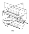
- FIG 1 there is shown schematically a quarto rolling mill comprising two working rolls (1) and (1 ⁇ ) and two support rolls (2) and (2 ⁇ ) .
- the axes of the cylinders are parallel and arranged along a clamping plane P1 passing through the contact generatrices.
- the rolled product 20 passes between the working rolls (1) and (1 ⁇ ) and its median plane corresponds substantially to the transverse plane of symmetry P2 of the whole of the rolling mill stand and in particular of the support rolls (2) and ( 2 ⁇ ).
- the cylinders are all aligned and centered on the same median plane P2.
- the working rolls (1) and (1 ⁇ ) can be moved axially relative to the centering position so that their respective transverse plane of symmetry is offset by one side or by one. other with respect to the median plane P2.
- an axial displacement force F1 is applied in one direction or the other to the working cylinders (1) and (1 ⁇ ).
- cambering forces F2 are applied to the ends of the shafts of the working cylinders (1) and (1 ⁇ ), by means of their chocks so as to camber the cylinder. corresponding.
- the working rolls (1) and (1 ⁇ ) can be subjected at the same time to an axial displacement force F1 and to the bending forces F2.
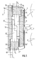
- FIG. 2 shows an end of a working cylinder with a chock, and an axial displacement device.
- the working cylinder (1) is provided at its two ends with centered pins, by means of bearings , inside chocks (3) forming a body bearing and sliding mounted, parallel to the clamping plane P1, in windows (40) formed in the two uprights (4) of the rolling stand.
- each chock (3) of the working cylinder 1 is provided with sliding faces (31) parallel to the clamping plane P1 and which can slide along corresponding faces ( 51) arranged inwards on support blocks (5) fixed in the windows (40) of the stand (4) of the rolling mill.
- each chock (3) guided between the two vertical faces (51) can move in two directions, on the one hand vertically under the action of the bending device and on the other hand parallel to the axis (10 ) of the cylinder under the action of the axial adjustment device.
- the axial displacement force which is applied to one of the chocks must be exerted exactly in the axis of the cylinder and, for this purpose, one can use, for example, a single jack supported on a lifting beam making it possible to apply the axial displacement force on the two sides of the chock.
- the displaced cylinder is a driving cylinder
- displacement cylinders (42) supplied in synchronism and placed symmetrically on either side of the means (43 ) driving the cylinder in rotation (1), the chock (3) being provided, on each side of the axis (10), hooking lugs (35) which engage in corresponding hooking heads integral with the rod of each jack (42).
- This attachment can advantageously be carried out in a removable manner by lateral displacement of the displacement cylinder (42) as shown in FIG. 2 for the right cylinder.
- each chock (3) of a cylinder (1) is secured to the latter in the axial direction by means of a cap (13) for closing the bearing cage, the latter being made of so as to be able to withstand axial forces, for example tapered bearings In this way, the axial displacement force applied by the jacks (42) on one of the chocks (3) is transmitted to the working cylinder and to the second chock placed at the other end of the latter.
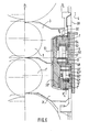
- Each chock (3) is also associated with a cambering assembly which, as shown schematically in Figure 6, generally consists of two pairs of jacks (6a, 66a) and (6 b , 66 b ) placed respectively on either side of the clamping plane P1 on which the axis of cylinder 1 is centered.
- each chock 3 is extended beyond the sliding faces (31) by bearing parts (32) in the form of ears which extend above the block. support (5) in which are housed the camber cylinders (6).
- the bending force is not applied directly to the chocks (3), but to intermediate pieces (7) which are interposed between the bending cylinders (6) and the corresponding bearing parts (32).
- Each support block (5) is common for the two working cylinders (1) and (1 ⁇ ) and comprises, at each end, at the top and at the bottom, a transverse recess (52) limited by two spaced parallel faces (54) at the clamping plane.
- Each intermediate piece (7) is provided with an external horizontal part (70) housed in the recess (52) and guided in translation along corresponding sliding faces on the two opposite faces (54) of the housing (52).
- each intermediate part (7) has the shape of a T, the external part (70) forming two horizontal wings (75) which extend symmetrically on either side of a vertical central part (73) centered in the median plane P3 of the support block (5) perpendicular to the clamping plane P1 that is to say the vertical plane of symmetry of the two pairs of camber cylinders in which the chock (3) of each is centered of two working cylinders (1 and 1 ⁇ ) when the latter are themselves aligned and centered on the median plane P2 of the cage.
- the vertical central part (73) of the intermediate piece (7) extends vertically between the two cylinders (6a, 66a) and engages in a machining (53) forming a central well formed in the support block (5) between the bores (67) of the two cylinders (6a, 66a) and which extends the transverse recess (52) in which extend the two wings (75) of the intermediate piece (7) to pass over the two cylinders (6a, 66a).
- the central part (73) constitutes a foot for guiding the intermediate part (7) mounted to slide vertically between two guide faces (55) parallel to the plane P3 and symmetrically spaced apart on either side of it and which constitute the two opposite sides of the central machining (53).
- the same arrangement is adopted for the cylinders (6 ⁇ a, 66 ⁇ a) for bending the lower cylinder (1 ⁇ ).
- the support block (5) which is common for the two working cylinders (1 and 1 ⁇ ) is therefore symmetrical, on the one hand, with respect to the vertical plane P3 and on the other hand, with respect to a horizontal plane.
- Each bore (67) is sealed by a partition (63) which constitutes the bottom of the transverse recess (52) and limits the chamber of the jack (6) closed, on the opposite side, by the partition 68 and inside which slides the piston (61) extended by a rod (62) which crosses the partition (63) to rest on the corresponding wing (75) of the intermediate piece (7).
- the two pairs of jacks (6a, 66a) (6 ⁇ a, 66 ⁇ a) thus formed on the two faces of the support block (5) can be supplied by hydraulic circuits as shown in FIG. 7, the support part (5) thus constituting a real fixed hydraulic block.
- the support lug (32) of the chock (3) is supported, by means of a thrust grain (33) on a smooth face (76) formed on the external part (70) of the intermediate piece (7) and along which the thrust grain (33) can therefore slide continuously following the axial displacements of the cylinder 1.
- the thrust grain (33) is placed in the transverse plane of symmetry of the chock (3) and is therefore centered in the plane P3 in the position shown in FIG. 4 for which the working rolls (1) and (1 ⁇ ) are aligned and centered in the median plane P2 of the cage.
- the support block (5) is common for the two cambering systems (6 and 6 ⁇ ) of the two working cylinders (1 and 1 ⁇ )
- the central parts forming the guide foot (73, 73 ⁇ ) of the two intermediate parts (7, 7 ⁇ ) engage in the same machining (53) which completely crosses the support block (5), in the axis thereof, connecting between them the transverse recesses (52 and 52 entre) and passing between the chambers of the four camber cylinders.
- each guide foot (73) of each intermediate part (7, 7 ⁇ ) is provided, at its end opposite to the external part (70), with an L-shaped notch which spares a thinned part (74) offset laterally so that the two guide feet (73, 73 ⁇ ) can overlap in the middle part of the central machining (53).
- each guide foot (73, 73 ⁇ ) can be guided practically all along the guide faces (55) formed over the entire height of the central machining (53).
- each chock is also centered in thrust planes P4 parallel to the clamping plane P1 and passing through the axes of the two corresponding camber cylinders.
- the thrust planes P4, P ⁇ 4 of the two cambering assemblies associated with the chocks (3 and 3 ⁇ ) and placed in the same support block 5 are offset on either side of the plane of symmetry of the support block 5 on which the machining is centered (53).
- each sliding part (7) moves vertically thanks to its guide foot (73) which opposes the moment of overturning resulting from the shifting of the thrust grain (33) relative to the plane of symmetry of the forces exerted by the jacks.
- the invention therefore makes it possible to carry out at the same time the axial adjustment and the bending of a working cylinder and, if the axial displacements remain reduced, as is most often the case, the moment of overturning of the intermediate part ( 7) which results can be easily collected by the embedding effect of the guide foot (7).
- the intermediate parts (7) and (7a) corresponding to the two chocks (3) and (3a) of each cylinder (1) and which are placed at the same level with respect to the axis of the cylinder, are integral with a beam (77) extending along the cylinder, parallel to its axis.
- This beam (77) can be dimensioned so as to absorb the moments of overturning of the parts (7) and (7a) due to the movement of the chocks (3) and (3a).
- a balancing of the forces applied by the bending cylinders is carried out as a function of the position of the corresponding chock.
- the offset of the displaced cylinder (1) is measured relative to the median plane P2 of the cage by means of a displacement sensor (44) consisting of two sliding parts, one relative to the other, fixed, for example on the two parts of one of the jacks (42) and providing an analog or digital signal proportional to the offset of the working cylinder relative to the centering position in the median plane P2 and of sign corresponding to the direction of the shift.
- This signal is used for balancing the pressures in the camber cylinders by means of a dis positive (8) shown diagrammatically in FIG. 7.
- a displaceable cylinder (1) and its two bending devices each consisting of two sets of jacks placed in hydraulic blocks (5a, 5b, 5 ⁇ c, 5 ⁇ d) each set comprising two jacks (6a, 66a), (6b, 66b), (6 ⁇ a, 66 ⁇ a) (6 ⁇ b, 66 ⁇ b).
- the reference 6 is assigned to the camber cylinders, placed on the side of the cylinder, that is to say towards the inside of the cage and the reference 66 to the cylinders placed towards the outside.
- the four jacks associated with each chock are arranged in the manner described above and are centered in two transverse planes R3 and R4 spaced from each other by a distance e.
- the hydraulic blocks (5a, 5b) and (5c, 5d) of the two chocks are connected by a single supply circuit (80) to a source of pressurized fluid not shown but the circuit (80) is divided into two branches ( 81) and (82) allowing the cylinders placed on the same side of the chock in the direction of axial displacement to be supplied at the same pressure.
- the branch (81) therefore supplies the jacks (6a, 6 b ,) and (66 c , 66 d ) in parallel of the two rows R3 and R ⁇ 4 placed on the right in FIG. 7 while the branch 82 supplies the jacks in parallel (66a, 66 b ,) and (6 c , 6 d ) of the two rows R4 and R ⁇ 3 placed on the left.
- the hydraulic circuit is designed so that, whatever the pressures, all the cylinders are supplied with the same flow rate so as to determine equal displacements at the same speed.
- Each branch (81), (82) of the supply circuit (8) is provided with a pressure regulator (83) which, depending on the signals received on its input (84) regulates the pressure in the corresponding circuit but in maintaining a constant flow.
- Each cylinder (1) is associated with an axial displacement sensor (44) providing an analog or digital signal proportional to the displacement and which is applied to a calculation unit (85).
- the latter develops the pressure setpoints S1 and S2 applied to the inputs (84) of the pressure regulators (83) of the two branches (81) and (82) according to a law programmed in the advance to ensure a distribution of pressures P1 and p2 such that the sum of the moments resulting from the thrust forces applied by the camber cylinders in the planes P4 and the reaction of the support part 32 of the corresponding chock on the T-shaped part is zero.
- the two rows of cylinders R3 and R4 may not be symmetrical with respect to the median plane P5 of the chock roll and this allows the cylinders to be arranged in the most adequate manner inside the hydraulic blocks (5) whose plane of symmetry does not necessarily coincide with that of the bearing.
- the various members used for balancing the pressures could be replaced by means fulfilling the same functions, these means being able to be hydraulic, electric or even mechanical (cam, lever arm, etc.).
- any technology for measuring displacements, calculating corrections and balancing pressures can be used to obtain the desired result.
- the fixed bending devices according to the invention can adapt to different diameters of cylinders and / or adapt to a variation in the diameter due wear, within the limit of the cylinder stroke.
Landscapes
- Engineering & Computer Science (AREA)
- Mechanical Engineering (AREA)
- Reduction Rolling/Reduction Stand/Operation Of Reduction Machine (AREA)
- Bending Of Plates, Rods, And Pipes (AREA)
- Control Of Metal Rolling (AREA)
- Soil Working Implements (AREA)
- Transplanting Machines (AREA)
- Metal Rolling (AREA)
Applications Claiming Priority (2)
| Application Number | Priority Date | Filing Date | Title |
|---|---|---|---|
| FR8702706 | 1987-02-27 | ||
| FR8702706A FR2611541B1 (fr) | 1987-02-27 | 1987-02-27 | Dispositif de reglage du profil et de repartition d'usure de cylindres dans un laminoir a cylindres deplacables axialement |
Publications (3)
| Publication Number | Publication Date |
|---|---|
| EP0283342A1 true EP0283342A1 (de) | 1988-09-21 |
| EP0283342B1 EP0283342B1 (de) | 1992-04-29 |
| EP0283342B2 EP0283342B2 (de) | 1997-01-22 |
Family
ID=9348449
Family Applications (1)
| Application Number | Title | Priority Date | Filing Date |
|---|---|---|---|
| EP88400372A Expired - Lifetime EP0283342B2 (de) | 1987-02-27 | 1988-02-18 | Walzgerüst mit axial verschiebbaren Walzen und Verfahren zum Steuern des Walzenprofils |
Country Status (8)
| Country | Link |
|---|---|
| US (1) | US4934166A (de) |
| EP (1) | EP0283342B2 (de) |
| JP (1) | JPH0751244B2 (de) |
| BR (1) | BR8800841A (de) |
| CA (1) | CA1294464C (de) |
| DE (1) | DE3870495D1 (de) |
| ES (1) | ES2031250T5 (de) |
| FR (1) | FR2611541B1 (de) |
Cited By (5)
| Publication number | Priority date | Publication date | Assignee | Title |
|---|---|---|---|---|
| GB2202173B (en) * | 1987-03-19 | 1991-08-14 | Davy Mckee | Rolling mill |
| FR2710567A1 (fr) * | 1993-09-28 | 1995-04-07 | Clecim Sa | Laminoir à déplacement axial. |
| WO2007121832A1 (de) * | 2006-04-21 | 2007-11-01 | Siemens Vai Metals Technologies Gmbh & Co | Biegevorrichtung für zwei arbeitswalzen eines walzgerüstes |
| WO2012049183A1 (de) * | 2010-10-12 | 2012-04-19 | Sms Siemag Ag | Walzgerüst |
| EP3981522A4 (de) * | 2019-10-25 | 2022-06-29 | Primetals Technologies Japan, Ltd. | Walzwerk |
Families Citing this family (15)
| Publication number | Priority date | Publication date | Assignee | Title |
|---|---|---|---|---|
| FR2611541B1 (fr) | 1987-02-27 | 1994-04-29 | Clecim Sa | Dispositif de reglage du profil et de repartition d'usure de cylindres dans un laminoir a cylindres deplacables axialement |
| GB2279023B (en) * | 1993-04-27 | 1996-06-05 | Ward Building Systems Ltd | Rolling mill |
| US5448901A (en) * | 1994-05-03 | 1995-09-12 | The University Of Toledo | Method for controlling axial shifting of rolls |
| US5752404A (en) * | 1996-12-17 | 1998-05-19 | Tippins Incorporated | Roll shifting system for rolling mills |
| US5970771A (en) * | 1998-07-10 | 1999-10-26 | Danieli United | Continuous spiral motion system for rolling mills |
| AT407124B (de) * | 1998-10-19 | 2000-12-27 | Voest Alpine Ind Anlagen | Biegevorrichtung für zwei arbeitswalzen eines walzgerüstes |
| IT1315119B1 (it) * | 2000-09-25 | 2003-02-03 | Danieli Off Mecc | Dispositivo e metodo per curvare i cilindri di una gabbia dilaminazione. |
| DE10334682A1 (de) * | 2003-07-30 | 2005-02-17 | Sms Demag Ag | Walzvorrichtung |
| US20070254230A1 (en) * | 2006-04-28 | 2007-11-01 | Xerox Corporation | External additive composition and process |
| DE102006051728B4 (de) * | 2006-10-30 | 2013-11-21 | Outokumpu Nirosta Gmbh | Verfahren zum Walzen von Metallbändern, inbesondere von Stahlbändern |
| DE102008035702A1 (de) * | 2008-07-30 | 2010-02-04 | Sms Siemag Aktiengesellschaft | Walzvorrichtung |
| DE102008049179A1 (de) | 2008-09-26 | 2010-04-01 | Sms Siemag Aktiengesellschaft | Walzvorrichtung |
| DE102009058876A1 (de) * | 2009-01-23 | 2010-07-29 | Sms Siemag Ag | Biege- und Ausbalanciervorrichtung für axial verschiebbare Arbeitswalzen eines Walzgerüstes |
| ITMI20101502A1 (it) * | 2010-08-05 | 2012-02-06 | Danieli Off Mecc | Sistema integrato di bending e shifting sotto carico per gabbie ad elevata apertura tra i rulli di lavoro |
| ITMI20120598A1 (it) | 2012-04-12 | 2013-10-13 | Danieli Off Mecc | Sistema integrato di piegatura e di bilanciamento per gabbie di laminazione |
Citations (6)
| Publication number | Priority date | Publication date | Assignee | Title |
|---|---|---|---|---|
| EP0067040A2 (de) * | 1981-06-03 | 1982-12-15 | Hitachi, Ltd. | Walzwerk |
| EP0084927A1 (de) * | 1982-01-06 | 1983-08-03 | Hitachi, Ltd. | Walzwerk |
| DE3331055A1 (de) * | 1983-08-29 | 1985-03-14 | SMS Schloemann-Siemag AG, 4000 Düsseldorf | Walzgeruest mit axial verschieblichen arbeitswalzen |
| DE3529364A1 (de) * | 1985-08-16 | 1987-02-19 | Schloemann Siemag Ag | Antriebsvorrichtung zur axialen verschiebung von walzen eines walzgeruestes |
| EP0233460A2 (de) * | 1986-01-17 | 1987-08-26 | Sms Schloemann-Siemag Aktiengesellschaft | Ständerfeste Biegevorrichtung für axial verschiebbare Walzen eines Mehrwalzengerüstes |
| EP0238377A1 (de) * | 1986-02-14 | 1987-09-23 | Clecim | Steuerung von Walzendurchbiegung in einem Walzgerüst mit axial verschiebbaren Walzen |
Family Cites Families (19)
| Publication number | Priority date | Publication date | Assignee | Title |
|---|---|---|---|---|
| JPS5666307A (en) * | 1979-10-04 | 1981-06-04 | Hitachi Ltd | Rolling mill |
| JPS58141808A (ja) * | 1982-02-19 | 1983-08-23 | Hitachi Ltd | 圧延機の板厚制御方法及び装置 |
| JPS5956910A (ja) * | 1982-09-27 | 1984-04-02 | Kawasaki Steel Corp | ロ−ルベンデイング押力制御方法 |
| JPS5987904A (ja) * | 1982-11-12 | 1984-05-21 | Mitsubishi Heavy Ind Ltd | ワ−クロ−ルベンデイングシリンダ装置 |
| JPS59153504A (ja) * | 1983-02-22 | 1984-09-01 | Ishikawajima Harima Heavy Ind Co Ltd | 圧延機 |
| JPS59185505A (ja) * | 1983-04-05 | 1984-10-22 | Ishikawajima Harima Heavy Ind Co Ltd | 圧延機 |
| JPS606212A (ja) * | 1983-06-23 | 1985-01-12 | Ishikawajima Harima Heavy Ind Co Ltd | 圧延機制御装置 |
| JPS6018210A (ja) * | 1983-07-13 | 1985-01-30 | Ishikawajima Harima Heavy Ind Co Ltd | 圧延機 |
| JPS6068103A (ja) * | 1983-09-22 | 1985-04-18 | Ishikawajima Harima Heavy Ind Co Ltd | 圧延機 |
| DE3409221A1 (de) * | 1984-03-14 | 1985-09-19 | SMS Schloemann-Siemag AG, 4000 Düsseldorf | Walzgeruest mit axial verschiebbaren arbeitswalzen |
| JPS619107U (ja) * | 1984-06-19 | 1986-01-20 | 石川島播磨重工業株式会社 | 圧延機 |
| JPS619108U (ja) * | 1984-06-19 | 1986-01-20 | 石川島播磨重工業株式会社 | 圧延機 |
| JPS6122940A (ja) * | 1984-07-10 | 1986-01-31 | 日産自動車株式会社 | 自動車用内装材 |
| JPH0616887B2 (ja) * | 1985-06-06 | 1994-03-09 | 株式会社日立製作所 | 圧延機のロ−ル形状制御装置 |
| JPH0679730B2 (ja) * | 1985-07-08 | 1994-10-12 | 株式会社日立製作所 | ロ−ルベンデイング装置 |
| GB8528848D0 (en) * | 1985-11-22 | 1985-12-24 | Davy Mckee Poole | Rolling mills |
| DE3604195C2 (de) * | 1986-02-07 | 1994-05-19 | Mannesmann Ag | Walzgerüst mit in Axialrichtung verschiebbaren Arbeits- oder Zwischenwalzen |
| FR2611541B1 (fr) | 1987-02-27 | 1994-04-29 | Clecim Sa | Dispositif de reglage du profil et de repartition d'usure de cylindres dans un laminoir a cylindres deplacables axialement |
| US4803865A (en) * | 1987-07-17 | 1989-02-14 | SMS Schloemann--Siemag Aktiengesellschaft | Stand-supported bending device for axially slidable rolls of a multiroll rolling mill |
-
1987
- 1987-02-27 FR FR8702706A patent/FR2611541B1/fr not_active Expired - Fee Related
-
1988
- 1988-02-18 ES ES88400372T patent/ES2031250T5/es not_active Expired - Lifetime
- 1988-02-18 EP EP88400372A patent/EP0283342B2/de not_active Expired - Lifetime
- 1988-02-18 DE DE8888400372T patent/DE3870495D1/de not_active Expired - Lifetime
- 1988-02-23 CA CA000559565A patent/CA1294464C/fr not_active Expired - Lifetime
- 1988-02-26 US US07/160,985 patent/US4934166A/en not_active Expired - Lifetime
- 1988-02-26 BR BR8800841A patent/BR8800841A/pt unknown
- 1988-02-27 JP JP63045690A patent/JPH0751244B2/ja not_active Expired - Fee Related
Patent Citations (6)
| Publication number | Priority date | Publication date | Assignee | Title |
|---|---|---|---|---|
| EP0067040A2 (de) * | 1981-06-03 | 1982-12-15 | Hitachi, Ltd. | Walzwerk |
| EP0084927A1 (de) * | 1982-01-06 | 1983-08-03 | Hitachi, Ltd. | Walzwerk |
| DE3331055A1 (de) * | 1983-08-29 | 1985-03-14 | SMS Schloemann-Siemag AG, 4000 Düsseldorf | Walzgeruest mit axial verschieblichen arbeitswalzen |
| DE3529364A1 (de) * | 1985-08-16 | 1987-02-19 | Schloemann Siemag Ag | Antriebsvorrichtung zur axialen verschiebung von walzen eines walzgeruestes |
| EP0233460A2 (de) * | 1986-01-17 | 1987-08-26 | Sms Schloemann-Siemag Aktiengesellschaft | Ständerfeste Biegevorrichtung für axial verschiebbare Walzen eines Mehrwalzengerüstes |
| EP0238377A1 (de) * | 1986-02-14 | 1987-09-23 | Clecim | Steuerung von Walzendurchbiegung in einem Walzgerüst mit axial verschiebbaren Walzen |
Non-Patent Citations (1)
| Title |
|---|
| PATENT ABSTRACTS OF JAPAN, vol. 9, no. 135 (M-386)[1858], 11 juin 1985; & JP-A-60 018 210 (ISHIKAWAJIMA HARIMA JUKOGYO K.K.) 30-01-1985 * |
Cited By (9)
| Publication number | Priority date | Publication date | Assignee | Title |
|---|---|---|---|---|
| GB2202173B (en) * | 1987-03-19 | 1991-08-14 | Davy Mckee | Rolling mill |
| FR2710567A1 (fr) * | 1993-09-28 | 1995-04-07 | Clecim Sa | Laminoir à déplacement axial. |
| EP0649686A1 (de) * | 1993-09-28 | 1995-04-26 | Clecim | Walzwerk mit axial verschiebaren Walzen |
| CN1050541C (zh) * | 1993-09-28 | 2000-03-22 | 克莱西姆公司 | 轴向移动式轧机 |
| WO2007121832A1 (de) * | 2006-04-21 | 2007-11-01 | Siemens Vai Metals Technologies Gmbh & Co | Biegevorrichtung für zwei arbeitswalzen eines walzgerüstes |
| US8196444B2 (en) | 2006-04-21 | 2012-06-12 | Siemens Vai Metals Technologies Gmbh | Bending device for two working rolls of a rolling stand |
| CN101426595B (zh) * | 2006-04-21 | 2012-07-11 | 西门子Vai金属技术有限责任公司 | 用于轧机机架的两个工作辊的弯曲装置 |
| WO2012049183A1 (de) * | 2010-10-12 | 2012-04-19 | Sms Siemag Ag | Walzgerüst |
| EP3981522A4 (de) * | 2019-10-25 | 2022-06-29 | Primetals Technologies Japan, Ltd. | Walzwerk |
Also Published As
| Publication number | Publication date |
|---|---|
| BR8800841A (pt) | 1988-10-04 |
| JPS63230208A (ja) | 1988-09-26 |
| CA1294464C (fr) | 1992-01-21 |
| JPH0751244B2 (ja) | 1995-06-05 |
| EP0283342B2 (de) | 1997-01-22 |
| FR2611541A1 (fr) | 1988-09-09 |
| FR2611541B1 (fr) | 1994-04-29 |
| ES2031250T5 (es) | 1997-03-16 |
| ES2031250T3 (es) | 1992-12-01 |
| EP0283342B1 (de) | 1992-04-29 |
| US4934166A (en) | 1990-06-19 |
| DE3870495D1 (de) | 1992-06-04 |
Similar Documents
| Publication | Publication Date | Title |
|---|---|---|
| EP0283342B1 (de) | Walzgerüst mit axial verschiebbaren Walzen und Verfahren zum Steuern des Walzenprofils | |
| EP1601474B1 (de) | Verfahren zum ändern der konfiguration eines walzgerüstes sowie ein zur durchführung des verfahrens geeignetes walzgerüst | |
| EP0238377B1 (de) | Steuerung von Walzendurchbiegung in einem Walzgerüst mit axial verschiebbaren Walzen | |
| FR2591919A1 (fr) | Machine-outil pour laminer par refoulement des pieces cylindriques creuses | |
| EP0649686B1 (de) | Walzwerk mit axial verschiebaren Walzen | |
| FR2641212A1 (fr) | Machine a cintrer | |
| EP0707902B1 (de) | Walzanlage | |
| EP2670540B1 (de) | Vorrichtung und verfahren zum kaltwalzen eines metallstreifens | |
| EP0070221B1 (de) | Druckverteilungseinrichtung für einen Werkzeugschlitten auf seine Führungsschiene | |
| FR2464105A1 (fr) | Dispositif pour regler le bombe du au flechissement de cylindres d'un laminoir | |
| EP0286533A1 (de) | Verfahren und Vorrichtung zum Walzen von Metallbändern oder Blechen | |
| FR2655907A1 (fr) | Presse plieuse hydraulique a tablier inferieur mobile. | |
| EP1005923B1 (de) | Walzwerk mit Mitteln zur Biegung der Arbeitswalzen | |
| FR2500368A1 (fr) | Presse hydraulique pour moulage de feuilles | |
| EP0975447B1 (de) | Walzanlage für flachprodukte | |
| EP0738546B1 (de) | Walzwerk mit grosser Öffnung | |
| WO1992020474A2 (fr) | Dispositif et procede permettant le formage a froid de cannelures sur la paroi d'une piece de revolution | |
| FR2661625A1 (fr) | Procede de remplacement des cylindres d'un laminoir et laminoir perfectionne pour la mise en óoeuvre du procede. | |
| FR2708219A1 (fr) | Procédé de compensation des déformations des tabliers de presses hydrauliques, tabliers et presses hydrauliques ainsi équipés. | |
| EP1044736B1 (de) | Walzwerk mit hydraulischer Anstellung | |
| EP3003590B1 (de) | Verfahren zum ändern der konfiguration eines walzwerks und walzwerk zur durchführung des verfahrens | |
| FR2607033A1 (fr) | Laminoir, en particulier laminoir a froid | |
| FR2537021A1 (fr) | Cage de laminoir | |
| FR2498491A1 (fr) | Procede de reglage de la position axiale d'un manchon monte avec jeu dans un laminoir | |
| FR2545014A1 (fr) | Dispositif de reglage mecanique et hydraulique de la position de travail d'un cylindre de laminoir |
Legal Events
| Date | Code | Title | Description |
|---|---|---|---|
| PUAI | Public reference made under article 153(3) epc to a published international application that has entered the european phase |
Free format text: ORIGINAL CODE: 0009012 |
|
| AK | Designated contracting states |
Kind code of ref document: A1 Designated state(s): BE DE ES GB IT NL |
|
| RAP1 | Party data changed (applicant data changed or rights of an application transferred) |
Owner name: CLECIM |
|
| 17P | Request for examination filed |
Effective date: 19890306 |
|
| 17Q | First examination report despatched |
Effective date: 19900907 |
|
| GRAA | (expected) grant |
Free format text: ORIGINAL CODE: 0009210 |
|
| AK | Designated contracting states |
Kind code of ref document: B1 Designated state(s): BE DE ES GB IT NL |
|
| REF | Corresponds to: |
Ref document number: 3870495 Country of ref document: DE Date of ref document: 19920604 |
|
| GBT | Gb: translation of ep patent filed (gb section 77(6)(a)/1977) | ||
| ITF | It: translation for a ep patent filed | ||
| REG | Reference to a national code |
Ref country code: ES Ref legal event code: FG2A Ref document number: 2031250 Country of ref document: ES Kind code of ref document: T3 |
|
| PLBI | Opposition filed |
Free format text: ORIGINAL CODE: 0009260 |
|
| PGFP | Annual fee paid to national office [announced via postgrant information from national office to epo] |
Ref country code: NL Payment date: 19930228 Year of fee payment: 6 |
|
| 26 | Opposition filed |
Opponent name: SMS SCHLOEMANN-SIEMAG AG Effective date: 19930129 |
|
| NLR1 | Nl: opposition has been filed with the epo |
Opponent name: SMS SCHLOEMANN-SIEMAG AG. |
|
| PG25 | Lapsed in a contracting state [announced via postgrant information from national office to epo] |
Ref country code: NL Effective date: 19940901 |
|
| NLV4 | Nl: lapsed or anulled due to non-payment of the annual fee | ||
| PLAW | Interlocutory decision in opposition |
Free format text: ORIGINAL CODE: EPIDOS IDOP |
|
| PLAW | Interlocutory decision in opposition |
Free format text: ORIGINAL CODE: EPIDOS IDOP |
|
| PUAH | Patent maintained in amended form |
Free format text: ORIGINAL CODE: 0009272 |
|
| STAA | Information on the status of an ep patent application or granted ep patent |
Free format text: STATUS: PATENT MAINTAINED AS AMENDED |
|
| RAP2 | Party data changed (patent owner data changed or rights of a patent transferred) |
Owner name: KVAERNER CLECIM |
|
| RAP4 | Party data changed (patent owner data changed or rights of a patent transferred) |
Owner name: KVAERNER CLECIM |
|
| 27A | Patent maintained in amended form |
Effective date: 19970122 |
|
| AK | Designated contracting states |
Kind code of ref document: B2 Designated state(s): BE DE ES GB IT NL |
|
| REG | Reference to a national code |
Ref country code: ES Ref legal event code: DC2A Kind code of ref document: T5 Effective date: 19970214 |
|
| ITF | It: translation for a ep patent filed | ||
| REG | Reference to a national code |
Ref country code: GB Ref legal event code: IF02 |
|
| PGFP | Annual fee paid to national office [announced via postgrant information from national office to epo] |
Ref country code: GB Payment date: 20040130 Year of fee payment: 17 |
|
| PGFP | Annual fee paid to national office [announced via postgrant information from national office to epo] |
Ref country code: DE Payment date: 20040203 Year of fee payment: 17 |
|
| PGFP | Annual fee paid to national office [announced via postgrant information from national office to epo] |
Ref country code: ES Payment date: 20040216 Year of fee payment: 17 |
|
| PGFP | Annual fee paid to national office [announced via postgrant information from national office to epo] |
Ref country code: BE Payment date: 20040401 Year of fee payment: 17 |
|
| PG25 | Lapsed in a contracting state [announced via postgrant information from national office to epo] |
Ref country code: IT Free format text: LAPSE BECAUSE OF NON-PAYMENT OF DUE FEES;WARNING: LAPSES OF ITALIAN PATENTS WITH EFFECTIVE DATE BEFORE 2007 MAY HAVE OCCURRED AT ANY TIME BEFORE 2007. THE CORRECT EFFECTIVE DATE MAY BE DIFFERENT FROM THE ONE RECORDED. Effective date: 20050218 Ref country code: GB Free format text: LAPSE BECAUSE OF NON-PAYMENT OF DUE FEES Effective date: 20050218 |
|
| PG25 | Lapsed in a contracting state [announced via postgrant information from national office to epo] |
Ref country code: ES Free format text: LAPSE BECAUSE OF NON-PAYMENT OF DUE FEES Effective date: 20050219 |
|
| PG25 | Lapsed in a contracting state [announced via postgrant information from national office to epo] |
Ref country code: BE Free format text: LAPSE BECAUSE OF NON-PAYMENT OF DUE FEES Effective date: 20050228 |
|
| BERE | Be: lapsed |
Owner name: *CLECIM Effective date: 20050228 |
|
| PG25 | Lapsed in a contracting state [announced via postgrant information from national office to epo] |
Ref country code: DE Free format text: LAPSE BECAUSE OF NON-PAYMENT OF DUE FEES Effective date: 20050901 |
|
| GBPC | Gb: european patent ceased through non-payment of renewal fee |
Effective date: 20050218 |
|
| REG | Reference to a national code |
Ref country code: ES Ref legal event code: FD2A Effective date: 20050219 |
|
| BERE | Be: lapsed |
Owner name: *CLECIM Effective date: 20050228 |