EP0283361A1 - Angepasstes Verbindungsteil des Armaturrohres eines Sitzes mit einer Verstellvorrichtung der Rückenlehnenneigung - Google Patents
Angepasstes Verbindungsteil des Armaturrohres eines Sitzes mit einer Verstellvorrichtung der Rückenlehnenneigung Download PDFInfo
- Publication number
- EP0283361A1 EP0283361A1 EP88400428A EP88400428A EP0283361A1 EP 0283361 A1 EP0283361 A1 EP 0283361A1 EP 88400428 A EP88400428 A EP 88400428A EP 88400428 A EP88400428 A EP 88400428A EP 0283361 A1 EP0283361 A1 EP 0283361A1
- Authority
- EP
- European Patent Office
- Prior art keywords
- tube
- seat
- flattened
- shaped
- part according
- Prior art date
- Legal status (The legal status is an assumption and is not a legal conclusion. Google has not performed a legal analysis and makes no representation as to the accuracy of the status listed.)
- Granted
Links
- 230000007246 mechanism Effects 0.000 claims abstract description 42
- 238000003466 welding Methods 0.000 claims description 5
- 230000008719 thickening Effects 0.000 claims description 3
- 230000002159 abnormal effect Effects 0.000 claims description 2
- 239000011324 bead Substances 0.000 claims description 2
- 238000005452 bending Methods 0.000 claims description 2
- 238000012423 maintenance Methods 0.000 claims description 2
- 230000002787 reinforcement Effects 0.000 description 5
- 239000002184 metal Substances 0.000 description 3
- 230000006835 compression Effects 0.000 description 2
- 238000007906 compression Methods 0.000 description 2
- 230000000712 assembly Effects 0.000 description 1
- 238000000429 assembly Methods 0.000 description 1
- 230000008030 elimination Effects 0.000 description 1
- 238000003379 elimination reaction Methods 0.000 description 1
- 238000009434 installation Methods 0.000 description 1
- XLYOFNOQVPJJNP-UHFFFAOYSA-N water Substances O XLYOFNOQVPJJNP-UHFFFAOYSA-N 0.000 description 1
Images

Classifications
-
- B—PERFORMING OPERATIONS; TRANSPORTING
- B60—VEHICLES IN GENERAL
- B60N—SEATS SPECIALLY ADAPTED FOR VEHICLES; VEHICLE PASSENGER ACCOMMODATION NOT OTHERWISE PROVIDED FOR
- B60N2/00—Seats specially adapted for vehicles; Arrangement or mounting of seats in vehicles
-
- B—PERFORMING OPERATIONS; TRANSPORTING
- B60—VEHICLES IN GENERAL
- B60N—SEATS SPECIALLY ADAPTED FOR VEHICLES; VEHICLE PASSENGER ACCOMMODATION NOT OTHERWISE PROVIDED FOR
- B60N2/00—Seats specially adapted for vehicles; Arrangement or mounting of seats in vehicles
- B60N2/68—Seat frames
- B60N2/682—Joining means
-
- B—PERFORMING OPERATIONS; TRANSPORTING
- B60—VEHICLES IN GENERAL
- B60N—SEATS SPECIALLY ADAPTED FOR VEHICLES; VEHICLE PASSENGER ACCOMMODATION NOT OTHERWISE PROVIDED FOR
- B60N2/00—Seats specially adapted for vehicles; Arrangement or mounting of seats in vehicles
- B60N2/02—Seats specially adapted for vehicles; Arrangement or mounting of seats in vehicles the seat or part thereof being movable, e.g. adjustable
- B60N2/22—Seats specially adapted for vehicles; Arrangement or mounting of seats in vehicles the seat or part thereof being movable, e.g. adjustable the back-rest being adjustable
Definitions
- the present invention overcomes these drawbacks by creating a shaped junction part of the ends of the seat and backrest frame tubes so that each articulation mechanism allowing the adjustment of the inclination of the backrest is directly mounted on the frames. thereby considerably reducing the cost price of the seat.
- the shaped joining part of the seat frame tube for fixing a tilt adjustment mechanism between the seat and the backrest is characterized in that each end of the frame of the seat 'seat and back is deformed by stamping, or similar means, to obtain a flat surface suitably stiffened by thickening zones or projecting lips thereby ensuring perfect application of the shaped end of the tube on the face of the flange considered of the articulation mechanism then these parts are connected to each other by different fixing means using, for centering these parts relative to each other, the joining pins of each flange of the articulation mechanism.
- the ends of the tubes forming the frame of the seat and the back of the seat with the fixed and mobile flanges of the articulation mechanisms are connected to each other by weld with addition, by using the junction pins of each mechanism articulation and weld points on the flat rear face of the shaped part.
- the flange / tube connections also allow the use of screw - nut or rivet solutions integral with the flanges.
- the good behavior of the tube is obtained by the fact that the bending forces pass along the axis of the tube, thus avoiding its twisting.
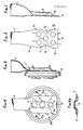
- Figs. 5, 6 and 7 show, respectively, an elevation view, part in section, a plan view and a cross-sectional view, of another form of the shaped part joining a seat frame tube. or of the back of a seat with a view to joining it with an articulation mechanism.
- Figs. 8, 9 and 10 show, respectively, an elevation view, part in section, a plan view and a cross-sectional view, of a third variant of the shaped part joining a seat frame tube. or file.
- Figs. 11, 12 and 13 are, respectively, a plan view, a side elevation view, part in section, and a cross-sectional view, of a fourth embodiment of the shaped part joining a back tube. or seat cushion.
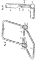
- Fig. 14 is a perspective view of a tubular partial frame of a seat with its articulation mechanisms.
- Fig. 15 is a front elevation of an articulation mechanism fixed on one of the sides of the seat by the shaped joining parts of the seat and back tubes.
- the stamping of the lower end of the tube 1 allows the creation of holes 3 arranged at predetermined locations for the junction of the end of the tube with one of the flanges of the articulation mechanism.
- a circular passage 2 intended for the installation of the control device of the articulation mechanism (s).
- the lower end of the tube referenced at 6 is flattened at 7 so as to form two non-contiguous outer lips 8 and 9, while the central zone 10 is reduced to the thickness of the walls of the tube and this zone is pierced with holes 11 for the passage of pins welded at 11a and allowing the fixing of the tube 6 on one of the flanges 12 of the articulation mechanism while an opening central 13 allows the passage of the single control shaft of the articulation mechanism (s).
- the end of the tube referenced at 15 has been shaped in a manner substantially similar to the case of FIGS. 3 and 4 but the lip 16 (see fig. 7) is perpendicular to the plane of junction of the walls of the tube 15 with the articulation mechanism while the lip 17 tends to extend parallel to the median plane of the articulation mechanism.
- the end of the tube referenced at 20 is shaped so as to present two vertical lips 21, 22 perpendicular to the plane of junction of the walls of the tube with respect to the articulation mechanism.
- FIG. 11 shows an asymmetrical arrangement of the flattened end of the tube referenced at 25 so that the junction with the flange considered of the articulation mechanism takes place at three points 26, 27, 28, the central opening 13 being intended for the passage of the single and combined control of the two articulation mechanisms.
- FIG. 13 shows a bead 25a and a lip 29 asymmetrical prominent ensuring, because of its location, a lateral reinforcement of the flattened end of the tube 25.
- the seat frame is shown diagrammatically by a tubular arch 50, the free ends 51 and 52 of which are flattened, for example, in a shape close to that shown in FIG. 4.
- the articulation mechanisms 53, 54 are thus fixed by their external fixed flanges on the arch 50.
- the arch 55 forming the back frame also has ends flattened 56, 57 which are fixed on the inner movable flange of each articulation mechanism 53, 54.
- ends flattened 56, 57 which are fixed on the inner movable flange of each articulation mechanism 53, 54.
- horizontal tubes 59, 60 are provided: the tube 59 forms a lower reinforcement of the backrest and the tube 60, a transverse reinforcement of the seat, thus perfectly stiffening, in the region of the articulation mechanisms 53, 54, the seat frame.
- the flat parts 1a to 1g (fig. 2), 10 (fig. 4a) and 25 (fig. 13) favor the maintenance of the closing ring of the mechanism preventing it from taking place during abnormal forces produced on the backrest and thus promote safety.
Landscapes
- Engineering & Computer Science (AREA)
- Aviation & Aerospace Engineering (AREA)
- Transportation (AREA)
- Mechanical Engineering (AREA)
- Chair Legs, Seat Parts, And Backrests (AREA)
- Seats For Vehicles (AREA)
- Chairs For Special Purposes, Such As Reclining Chairs (AREA)
- Telephone Set Structure (AREA)
- Mechanical Coupling Of Light Guides (AREA)
- Fire-Detection Mechanisms (AREA)
- Quick-Acting Or Multi-Walled Pipe Joints (AREA)
- Mutual Connection Of Rods And Tubes (AREA)
- Joints Allowing Movement (AREA)
Priority Applications (1)
| Application Number | Priority Date | Filing Date | Title |
|---|---|---|---|
| AT88400428T ATE58683T1 (de) | 1987-03-04 | 1988-02-24 | Angepasstes verbindungsteil des armaturrohres eines sitzes mit einer verstellvorrichtung der rueckenlehnenneigung. |
Applications Claiming Priority (2)
| Application Number | Priority Date | Filing Date | Title |
|---|---|---|---|
| FR8702953A FR2611827B1 (fr) | 1987-03-04 | 1987-03-04 | Partie de jonction conformee de tube d'armature de siege avec un mecanisme de reglage d'inclinaison du dossier |
| FR8702953 | 1987-03-04 |
Publications (2)
| Publication Number | Publication Date |
|---|---|
| EP0283361A1 true EP0283361A1 (de) | 1988-09-21 |
| EP0283361B1 EP0283361B1 (de) | 1990-11-28 |
Family
ID=9348606
Family Applications (1)
| Application Number | Title | Priority Date | Filing Date |
|---|---|---|---|
| EP88400428A Expired - Lifetime EP0283361B1 (de) | 1987-03-04 | 1988-02-24 | Angepasstes Verbindungsteil des Armaturrohres eines Sitzes mit einer Verstellvorrichtung der Rückenlehnenneigung |
Country Status (15)
| Country | Link |
|---|---|
| US (1) | US5050932A (de) |
| EP (1) | EP0283361B1 (de) |
| JP (1) | JP2740178B2 (de) |
| KR (1) | KR920004597B1 (de) |
| CN (1) | CN88101161A (de) |
| AT (1) | ATE58683T1 (de) |
| AU (1) | AU1260888A (de) |
| BR (1) | BR8800919A (de) |
| CA (1) | CA1280350C (de) |
| DE (1) | DE3861144D1 (de) |
| DK (1) | DK109888A (de) |
| ES (1) | ES2019131B3 (de) |
| FR (1) | FR2611827B1 (de) |
| PT (1) | PT86888A (de) |
| ZA (1) | ZA881507B (de) |
Cited By (3)
| Publication number | Priority date | Publication date | Assignee | Title |
|---|---|---|---|---|
| EP1506891A3 (de) * | 2003-08-09 | 2008-04-16 | Vogelsitze GmbH | Fahrgastsitz für Personenbeförderungsfahrzeuge |
| EP2210772A4 (de) * | 2007-11-20 | 2011-06-08 | Aisin Seiki | Fahrzeugsitzrahmen |
| CN106965726A (zh) * | 2016-01-11 | 2017-07-21 | 安道拓卢森堡控股有限公司 | 车辆座椅 |
Families Citing this family (22)
| Publication number | Priority date | Publication date | Assignee | Title |
|---|---|---|---|---|
| US5338100A (en) * | 1992-02-24 | 1994-08-16 | Itt Corporation | High strength automotive seat frame and method |
| US5499863A (en) * | 1993-05-17 | 1996-03-19 | Toyota Shatai Kabushiki Kaisha | Seat back frame |
| US5570508A (en) * | 1993-12-03 | 1996-11-05 | Itt Industries, Inc. | Method of making a high strength automotive seat frame |
| FR2720141B1 (fr) * | 1994-05-20 | 1996-08-02 | Cesa | Elément perfectionné d'armature pour siège, pièce en faisant utilisation et son application notamment à un siège de véhicule. |
| US5568961A (en) * | 1994-08-10 | 1996-10-29 | Findlay Industries | Tubular seat frame |
| WO1996019932A1 (en) * | 1994-12-27 | 1996-07-04 | Kokuyo Co., Ltd. | Folding chair |
| FR2753935B1 (fr) * | 1996-10-02 | 1998-12-04 | Faure Bertrand Equipements Sa | Procede pour realiser un siege de vehicule, et siege realise selon ce procede |
| US6189975B1 (en) * | 1998-03-05 | 2001-02-20 | Aisin Seiki Kabushiki Kaisha | Seat frame assembly |
| US6106071A (en) * | 1998-05-12 | 2000-08-22 | Johnson Controls Technology Company | Twin frame seat assembly |
| JP2003061777A (ja) * | 2001-08-27 | 2003-03-04 | Aisin Seiki Co Ltd | シートフレーム |
| US6682146B2 (en) * | 2001-11-28 | 2004-01-27 | Taichi-S Co., Ltd. | Structure of seat cushion frame in vehicle seat |
| US6672662B1 (en) * | 2001-12-26 | 2004-01-06 | Lear Corporation | Vehicle seat |
| DE102007039363B4 (de) * | 2006-11-23 | 2015-03-19 | Johnson Controls Metals and Mechanisms GmbH & Co. KG | Verstellvorrichtung in einem Kraftfahrzeug mit einem bewegbaren Verstellteil und Verfahren zu seiner Herstellung |
| US7717519B2 (en) * | 2006-12-22 | 2010-05-18 | The Boeing Company | Composite seat back structure for a lightweight aircraft seat assembly |
| WO2009149177A1 (en) * | 2008-06-03 | 2009-12-10 | Johnson Controls Technology Company | Seat frame - tailored tubes |
| US8096620B2 (en) * | 2009-04-28 | 2012-01-17 | International Truck Intellectual Property Company, Llc | Injection mold seat riser for modular school bus seats |
| JP5545095B2 (ja) * | 2010-07-26 | 2014-07-09 | トヨタ紡織株式会社 | 車両用シートフレーム |
| DE102010049328A1 (de) * | 2010-10-19 | 2012-04-19 | Keiper Gmbh & Co. Kg | Fahrzeugsitz, insbesondere Kraftfahrzeugsitz |
| US9126516B2 (en) * | 2012-06-22 | 2015-09-08 | Toyota Motor Engineering & Manufacturing North America, Inc. | Symmetrically designed outer side member for a seat |
| EP3033974B1 (de) * | 2014-12-19 | 2017-05-24 | EMU Group S.p.A. | Stützvorrichtung zum tragen einer person in ruhe, mit eine starre tragkonstruktion mit stütz elemente für diese person |
| JP6578741B2 (ja) * | 2015-05-25 | 2019-09-25 | トヨタ紡織株式会社 | 乗物用シートのリクライナ取付用ブラケット |
| US11975639B2 (en) * | 2021-12-20 | 2024-05-07 | Lear Corporation | Seat back frame for impact deformation |
Citations (4)
| Publication number | Priority date | Publication date | Assignee | Title |
|---|---|---|---|---|
| FR2323546A1 (fr) * | 1975-09-04 | 1977-04-08 | Gustafsson Gustaf | Mecanisme reglable, notamment pour siege de vehicule automobile |
| GB2036550A (en) * | 1978-11-20 | 1980-07-02 | Brandoli Luigi | Longitudinal cross-member for a vehicle seat |
| GB2088711A (en) * | 1980-10-29 | 1982-06-16 | Vere William Ltd | Chairs |
| FR2510375A1 (fr) * | 1981-07-31 | 1983-02-04 | Keiper Automobiltechnik Gmbh | Ferrure d'articulation pour sieges a dossier reglable, notamment pour sieges de vehicules |
Family Cites Families (5)
| Publication number | Priority date | Publication date | Assignee | Title |
|---|---|---|---|---|
| US2851090A (en) * | 1956-07-31 | 1958-09-09 | Hamilton Mfg Corp | Chair |
| US4492408A (en) * | 1982-01-19 | 1985-01-08 | Allen Industries, Inc. | Vehicle seat construction and method of making the same |
| FR2515583A1 (fr) * | 1983-04-19 | 1983-05-06 | Peugeot Cycles | Tige d'articulation de siege a dossier inclinable et systeme de reglage de l'inclinaison comportant une telle tige |
| US4473318A (en) | 1983-06-23 | 1984-09-25 | The Boeing Company | Passive structures tubing connector terminal |
| US4575153A (en) * | 1984-05-02 | 1986-03-11 | Tachikawa Spring Co. Ltd. | Back frame in a seat back for a vehicle seat |
-
1987
- 1987-03-04 FR FR8702953A patent/FR2611827B1/fr not_active Expired
-
1988
- 1988-02-24 EP EP88400428A patent/EP0283361B1/de not_active Expired - Lifetime
- 1988-02-24 DE DE8888400428T patent/DE3861144D1/de not_active Expired - Fee Related
- 1988-02-24 AT AT88400428T patent/ATE58683T1/de active
- 1988-02-24 ES ES88400428T patent/ES2019131B3/es not_active Expired - Lifetime
- 1988-03-01 DK DK109888A patent/DK109888A/da not_active Application Discontinuation
- 1988-03-03 AU AU12608/88A patent/AU1260888A/en not_active Abandoned
- 1988-03-03 CA CA000560495A patent/CA1280350C/en not_active Expired - Fee Related
- 1988-03-03 PT PT86888A patent/PT86888A/pt not_active Application Discontinuation
- 1988-03-03 JP JP63050579A patent/JP2740178B2/ja not_active Expired - Fee Related
- 1988-03-03 BR BR8800919A patent/BR8800919A/pt unknown
- 1988-03-03 ZA ZA881507A patent/ZA881507B/xx unknown
- 1988-03-03 CN CN198888101161A patent/CN88101161A/zh active Pending
- 1988-03-04 KR KR1019880002330A patent/KR920004597B1/ko not_active Expired
-
1989
- 1989-10-11 US US07/421,318 patent/US5050932A/en not_active Expired - Lifetime
Patent Citations (4)
| Publication number | Priority date | Publication date | Assignee | Title |
|---|---|---|---|---|
| FR2323546A1 (fr) * | 1975-09-04 | 1977-04-08 | Gustafsson Gustaf | Mecanisme reglable, notamment pour siege de vehicule automobile |
| GB2036550A (en) * | 1978-11-20 | 1980-07-02 | Brandoli Luigi | Longitudinal cross-member for a vehicle seat |
| GB2088711A (en) * | 1980-10-29 | 1982-06-16 | Vere William Ltd | Chairs |
| FR2510375A1 (fr) * | 1981-07-31 | 1983-02-04 | Keiper Automobiltechnik Gmbh | Ferrure d'articulation pour sieges a dossier reglable, notamment pour sieges de vehicules |
Cited By (4)
| Publication number | Priority date | Publication date | Assignee | Title |
|---|---|---|---|---|
| EP1506891A3 (de) * | 2003-08-09 | 2008-04-16 | Vogelsitze GmbH | Fahrgastsitz für Personenbeförderungsfahrzeuge |
| EP2210772A4 (de) * | 2007-11-20 | 2011-06-08 | Aisin Seiki | Fahrzeugsitzrahmen |
| US8267479B2 (en) | 2007-11-20 | 2012-09-18 | Aisin Seiki Kabushiki Kaisha | Vehicle seat frame |
| CN106965726A (zh) * | 2016-01-11 | 2017-07-21 | 安道拓卢森堡控股有限公司 | 车辆座椅 |
Also Published As
| Publication number | Publication date |
|---|---|
| CN88101161A (zh) | 1988-09-14 |
| KR880010941A (ko) | 1988-10-25 |
| JP2740178B2 (ja) | 1998-04-15 |
| ATE58683T1 (de) | 1990-12-15 |
| DE3861144D1 (de) | 1991-01-10 |
| ZA881507B (en) | 1988-08-24 |
| US5050932A (en) | 1991-09-24 |
| KR920004597B1 (ko) | 1992-06-11 |
| FR2611827A1 (fr) | 1988-09-09 |
| DK109888A (da) | 1988-09-05 |
| BR8800919A (pt) | 1988-10-11 |
| AU1260888A (en) | 1988-09-08 |
| JPS63242209A (ja) | 1988-10-07 |
| DK109888D0 (da) | 1988-03-01 |
| ES2019131B3 (es) | 1991-06-01 |
| CA1280350C (en) | 1991-02-19 |
| EP0283361B1 (de) | 1990-11-28 |
| PT86888A (pt) | 1989-03-30 |
| FR2611827B1 (fr) | 1989-07-28 |
Similar Documents
| Publication | Publication Date | Title |
|---|---|---|
| EP0283361B1 (de) | Angepasstes Verbindungsteil des Armaturrohres eines Sitzes mit einer Verstellvorrichtung der Rückenlehnenneigung | |
| FR2895334A1 (fr) | Dispositif de siege de vehicule | |
| FR2733945A1 (fr) | Dispositif d'armature de dossier pour siege arriere de vehicule automobile, et siege comportant un tel dispositif | |
| FR2806675A1 (fr) | Siege de vehicule comportant un mecanisme de rehausse, et dispositif de commande pour un tel siege | |
| JP2000350636A (ja) | 乗物用シートの背もたれ構造 | |
| FR2775448A1 (fr) | Bati de siege d'un siege de vehicule automobile | |
| EP2475533B1 (de) | Modulare fahrzeugachse, insbesondere für kraftfahrzeuge | |
| EP0259201B1 (de) | Sitzgestell, besonders mit verstellbarer Rückenlehne | |
| EP0671312B1 (de) | Kraftwagenstruktur mit mindestens einer Knotenpunktverbindung für langgestreckte Elemente, wie Rahmenlangsträger, Pfosten, Querträger des Wagens | |
| EP1529720A1 (de) | Strukturelles Rohrbauteil für ein Kraftfahrzeug | |
| JPH08228878A (ja) | 車両シート用のシートベース骨組およびその製造方法 | |
| EP1517805B1 (de) | Aufhängungsarm und herstellungsverfahren dafür | |
| WO2010049626A1 (fr) | Ensemble de traverse de planche de bord pour véhicule automobile, dispositif pour planche de bord, véhicule et procédé de fabrication correspondants | |
| EP2763885B1 (de) | Querträgeranordnung eines kraftfahrzeugarmaturenbretts und kraftfahrzeug mit einer solchen anordnung | |
| EP4048549B1 (de) | Rahmen für einen kraftfahrzeugsitz und zugehöriger fahrzeugsitz | |
| US6435613B1 (en) | Part of a motor vehicle seat | |
| US6767068B1 (en) | Dual reclining device for vehicle seat | |
| FR2759332A1 (fr) | Siege perfectionne pour vehicule automobile | |
| EP0565390B1 (de) | Mehrfach verstellbarer Sitz | |
| EP0636510A1 (de) | Gelenkbeschlag für Fahrzeugsitz | |
| FR3121647A3 (fr) | Dossier de siège de véhicule, siège de véhicule comprenant un tel dossier et ensemble de siège comprenant un tel siège | |
| WO2023052698A1 (fr) | Support de platine porte-moyeu et vehicule comportant un tel support | |
| FR2789630A1 (fr) | Agencement de renfort de porte pour vehicule automobile | |
| EP3795414A1 (de) | Gestell für sitzfläche eines sitzes für kraftfahrzeug | |
| FR2937930A1 (fr) | Dispositif de fixation d'une ceinture de securite et plancher de vehicule automobile equipe d'un tel dispositif. |
Legal Events
| Date | Code | Title | Description |
|---|---|---|---|
| PUAI | Public reference made under article 153(3) epc to a published international application that has entered the european phase |
Free format text: ORIGINAL CODE: 0009012 |
|
| 17P | Request for examination filed |
Effective date: 19880227 |
|
| AK | Designated contracting states |
Kind code of ref document: A1 Designated state(s): AT BE CH DE ES GB GR IT LI LU NL SE |
|
| 17Q | First examination report despatched |
Effective date: 19891030 |
|
| GRAA | (expected) grant |
Free format text: ORIGINAL CODE: 0009210 |
|
| AK | Designated contracting states |
Kind code of ref document: B1 Designated state(s): AT BE CH DE ES GB GR IT LI LU NL SE |
|
| PG25 | Lapsed in a contracting state [announced via postgrant information from national office to epo] |
Ref country code: GR Free format text: LAPSE BECAUSE OF FAILURE TO SUBMIT A TRANSLATION OF THE DESCRIPTION OR TO PAY THE FEE WITHIN THE PRESCRIBED TIME-LIMIT Effective date: 19901128 Ref country code: AT Effective date: 19901128 |
|
| REF | Corresponds to: |
Ref document number: 58683 Country of ref document: AT Date of ref document: 19901215 Kind code of ref document: T |
|
| REF | Corresponds to: |
Ref document number: 3861144 Country of ref document: DE Date of ref document: 19910110 |
|
| GBT | Gb: translation of ep patent filed (gb section 77(6)(a)/1977) | ||
| ITF | It: translation for a ep patent filed | ||
| PG25 | Lapsed in a contracting state [announced via postgrant information from national office to epo] |
Ref country code: LU Free format text: LAPSE BECAUSE OF NON-PAYMENT OF DUE FEES Effective date: 19910228 Ref country code: LI Effective date: 19910228 Ref country code: CH Effective date: 19910228 |
|
| PGFP | Annual fee paid to national office [announced via postgrant information from national office to epo] |
Ref country code: NL Payment date: 19910228 Year of fee payment: 4 |
|
| PLBE | No opposition filed within time limit |
Free format text: ORIGINAL CODE: 0009261 |
|
| STAA | Information on the status of an ep patent application or granted ep patent |
Free format text: STATUS: NO OPPOSITION FILED WITHIN TIME LIMIT |
|
| REG | Reference to a national code |
Ref country code: CH Ref legal event code: PL |
|
| 26N | No opposition filed | ||
| PGFP | Annual fee paid to national office [announced via postgrant information from national office to epo] |
Ref country code: BE Payment date: 19920227 Year of fee payment: 5 |
|
| ITTA | It: last paid annual fee | ||
| PG25 | Lapsed in a contracting state [announced via postgrant information from national office to epo] |
Ref country code: NL Effective date: 19920901 |
|
| NLV4 | Nl: lapsed or anulled due to non-payment of the annual fee | ||
| PGFP | Annual fee paid to national office [announced via postgrant information from national office to epo] |
Ref country code: GB Payment date: 19930216 Year of fee payment: 6 |
|
| PGFP | Annual fee paid to national office [announced via postgrant information from national office to epo] |
Ref country code: SE Payment date: 19930222 Year of fee payment: 6 |
|
| PG25 | Lapsed in a contracting state [announced via postgrant information from national office to epo] |
Ref country code: BE Effective date: 19930228 |
|
| BERE | Be: lapsed |
Owner name: A.& M. COUSIN ETS COUSIN FRERES Effective date: 19930228 |
|
| PG25 | Lapsed in a contracting state [announced via postgrant information from national office to epo] |
Ref country code: GB Effective date: 19940224 |
|
| PG25 | Lapsed in a contracting state [announced via postgrant information from national office to epo] |
Ref country code: SE Effective date: 19940225 |
|
| GBPC | Gb: european patent ceased through non-payment of renewal fee |
Effective date: 19940224 |
|
| EUG | Se: european patent has lapsed |
Ref document number: 88400428.4 Effective date: 19940910 |
|
| PGFP | Annual fee paid to national office [announced via postgrant information from national office to epo] |
Ref country code: ES Payment date: 19980218 Year of fee payment: 11 |
|
| PG25 | Lapsed in a contracting state [announced via postgrant information from national office to epo] |
Ref country code: ES Free format text: LAPSE BECAUSE OF EXPIRATION OF PROTECTION Effective date: 19990225 |
|
| REG | Reference to a national code |
Ref country code: ES Ref legal event code: FD2A Effective date: 20010601 |
|
| PG25 | Lapsed in a contracting state [announced via postgrant information from national office to epo] |
Ref country code: IT Free format text: LAPSE BECAUSE OF NON-PAYMENT OF DUE FEES;WARNING: LAPSES OF ITALIAN PATENTS WITH EFFECTIVE DATE BEFORE 2007 MAY HAVE OCCURRED AT ANY TIME BEFORE 2007. THE CORRECT EFFECTIVE DATE MAY BE DIFFERENT FROM THE ONE RECORDED. Effective date: 20050224 |
|
| PGFP | Annual fee paid to national office [announced via postgrant information from national office to epo] |
Ref country code: DE Payment date: 20060125 Year of fee payment: 19 |
|
| PG25 | Lapsed in a contracting state [announced via postgrant information from national office to epo] |
Ref country code: DE Free format text: LAPSE BECAUSE OF NON-PAYMENT OF DUE FEES Effective date: 20070901 |