EP0283541A1 - Procédé et appareil pour rétrécir une housse en plastique autour d'une charge palettisée - Google Patents
Procédé et appareil pour rétrécir une housse en plastique autour d'une charge palettisée Download PDFInfo
- Publication number
- EP0283541A1 EP0283541A1 EP19870104515 EP87104515A EP0283541A1 EP 0283541 A1 EP0283541 A1 EP 0283541A1 EP 19870104515 EP19870104515 EP 19870104515 EP 87104515 A EP87104515 A EP 87104515A EP 0283541 A1 EP0283541 A1 EP 0283541A1
- Authority
- EP
- European Patent Office
- Prior art keywords
- suction
- heat
- film
- hood
- goods
- Prior art date
- Legal status (The legal status is an assumption and is not a legal conclusion. Google has not performed a legal analysis and makes no representation as to the accuracy of the status listed.)
- Granted
Links
- 238000000034 method Methods 0.000 title claims abstract description 18
- 239000004033 plastic Substances 0.000 title claims abstract 9
- 238000001816 cooling Methods 0.000 claims abstract description 5
- 239000011248 coating agent Substances 0.000 claims description 4
- 238000000576 coating method Methods 0.000 claims description 4
- -1 polytetrafluoroethylene Polymers 0.000 claims description 2
- 229920001343 polytetrafluoroethylene Polymers 0.000 claims description 2
- 239000004810 polytetrafluoroethylene Substances 0.000 claims description 2
- 238000004519 manufacturing process Methods 0.000 claims 1
- 238000004026 adhesive bonding Methods 0.000 abstract 2
- 239000005022 packaging material Substances 0.000 abstract 1
- 238000011144 upstream manufacturing Methods 0.000 abstract 1
- 239000000463 material Substances 0.000 description 4
- 239000011888 foil Substances 0.000 description 3
- 238000010438 heat treatment Methods 0.000 description 3
- 230000015572 biosynthetic process Effects 0.000 description 2
- 230000000694 effects Effects 0.000 description 2
- 230000000284 resting effect Effects 0.000 description 2
- 230000001960 triggered effect Effects 0.000 description 2
- 206010000060 Abdominal distension Diseases 0.000 description 1
- 238000010521 absorption reaction Methods 0.000 description 1
- 208000024330 bloating Diseases 0.000 description 1
- 238000002485 combustion reaction Methods 0.000 description 1
- 238000006073 displacement reaction Methods 0.000 description 1
- 230000002349 favourable effect Effects 0.000 description 1
- 235000015243 ice cream Nutrition 0.000 description 1
- 235000013310 margarine Nutrition 0.000 description 1
- 239000003264 margarine Substances 0.000 description 1
- 238000005259 measurement Methods 0.000 description 1
- 238000002156 mixing Methods 0.000 description 1
- 230000001681 protective effect Effects 0.000 description 1
- 230000005855 radiation Effects 0.000 description 1
- 238000007493 shaping process Methods 0.000 description 1
- 229920006300 shrink film Polymers 0.000 description 1
- 230000008961 swelling Effects 0.000 description 1
Images


Classifications
-
- B—PERFORMING OPERATIONS; TRANSPORTING
- B65—CONVEYING; PACKING; STORING; HANDLING THIN OR FILAMENTARY MATERIAL
- B65B—MACHINES, APPARATUS OR DEVICES FOR, OR METHODS OF, PACKAGING ARTICLES OR MATERIALS; UNPACKING
- B65B53/00—Shrinking wrappers, containers, or container covers during or after packaging
- B65B53/02—Shrinking wrappers, containers, or container covers during or after packaging by heat
- B65B53/06—Shrinking wrappers, containers, or container covers during or after packaging by heat supplied by gases, e.g. hot-air jets
- B65B53/066—Mobile frames, hoods, posts or the like
Definitions
- the invention relates to a method and a device for shrink-fitting a film hood located on a palletized stack of goods in accordance with the preamble of claim 1.
- the object of the invention is to provide a method and a device suitable for carrying it out in such a way that the film hood, even with very ample dimensioning and extensive extent, in the formation of the air cushion with respect to it being movable relative to it and applying heat Heat sources do not touch them and do not come too close to them without the risk that the film hood will touch the stack of materials in the edge area.
- the air cushion produced in the manner according to the invention is thus designed in a controlled manner so that the position of the film between the stack of goods on the one hand and the heat source on the other hand is reliably stabilized.
- the area-related limitation of the intake precludes the possibility of large-area lifting. Nevertheless, it is always ensured that there is a distance from the packaged goods in the heat application zone, which excludes heat transfer to the latter.
- the suction which is carried out with pneumatic means, allows the heat to be applied not only to burners which are arranged in a frame-like manner, but also to arrange a vertical burner strip, between which and the stack of goods there is a rotary movement.
- the air cushion adapts precisely not only in its distance from the stack of goods and the heat source, but also with regard to its longitudinal extent to the given heat application requirements. It is therefore possible to choose those arrangements which are intended for operation in the ambient atmosphere without impairing the shrinking effect.
- a particularly advantageous embodiment of the invention provides for the film wall to be lifted off from the stack of materials when the film wall is subjected to heat by means of a hot gas stream in such a way that a waveform results.
- the latter can also be designed for a wider zone in accordance with the cooling and shrinking conditions than is the case with the leading suction.
- the amplitudes of the wave crests do not necessarily have to match. Extensive possibilities for shaping the wave profile can be realized if the suction directions are set to be pivotable accordingly.
- the heat exposure can also be ensured by a line burner in which a generally horizontally extending flame band consists of a mixing chamber along a gap and is then mixed with cold air in the same way as individual burners .
- a line burner in which a generally horizontally extending flame band consists of a mixing chamber along a gap and is then mixed with cold air in the same way as individual burners .
- infrared heaters which in turn can be heated electrically or by special burners.
- the heating power is selected in the usual way so that the foils, which are between about 50 to 250 ⁇ m thick, are adequately plasticized, in order then to shrink on cooling.
- the present invention allows a particularly effective mode of operation when the suction of the film wall takes place without contact.
- the prerequisites for the non-contact lifting of the film can be guaranteed by appropriate controls of the suction vacuum. It is important for this that the greatest possible negative pressure does not exist in the suction nozzles, but that air is always sucked in through the suction nozzles.
- the suction nozzles are superior to a sucking bar with a nozzle inlet, because suction nozzles can be individually adjusted to certain suction forces. The latter is of importance, for example, when the withdrawal has to be carried out in certain areas. This is particularly the case in the sensitive corner areas of the stack of goods.
- the heat application zone and the suction areas are particularly advantageously guided from bottom to top. This can be achieved with devices that enclose the stack of goods like a frame. Special attention must be paid to the start and end conditions of the shrinking process. So it is important at the beginning that the foil wall hanging over the edge of the free-standing pallet is first fixed.
- Known options provide for a central suction by means of a blower, for example the proposal according to patent application P 30 14 369.2-27.
- Such a folding of the free edge of the film can also be favored in that, according to the present invention, the center of the stack of goods is blown, changing its position during shrinking, whereupon the pallet is set down.
- the hood cover furthermore requires special attention, since it must be ensured that it is lifted off evenly from the end face of the stack of goods. This is achieved in that when the top edge of the hood enters the heat application zone, an air flow is guided horizontally to slightly obliquely downwards over the hood ceiling.
- the device according to the invention which is especially designed to carry out the method according to the invention, is based on the same prior art as the method according to the invention.
- the device according to the invention is also intended to solve the same problem.
- the device according to the invention leads to an arrangement in which suction is carried out in front of the heat application zone running along a line, with suction devices, so that a lifting-off region of the film wall results parallel and leading to the heat application zone .
- This arrangement ensures, in particular in connection with a further suction device downstream of the heat source, a wave-like course of the film wall, so that a wave trough is enclosed by two wave crests, this formation moving upwards simultaneously with the displacement of the heat source and the suction devices.
- the heat source and the suction device therefore appropriately surround the stack of goods in a frame-like manner in each case in horizontal planes, wherein they can be displaced in the vertical direction.
- the heat source and the suction devices are expediently formed on pipe sections. So that there is a particularly pronounced lifting in the corner areas, these pipe sections, which are arranged at a distance from the film wall, project in one plane above the edges of the stack of goods.
- Effective suction performance results from nozzle-like entries into the suction devices. This not only largely avoids pressure losses, but also creates favorable conditions for controlling the intake power.
- the heat source consists of nozzles inserted into the proposed pipe sections, which are shared Have gas connection.
- a compressed air outlet is advantageously arranged, via which not only combustion air is supplied, but at the same time the cold air flows out to lower the hot gas temperature, the hot gas jet then being given a specific direction, generally downwards, by the corresponding position of the compressed air outlet openings. can be given.
- the pallet In the starting position, the pallet is in a known manner in the raised state, the film edges hanging down over the lower edge of the pallet. In order to reliably establish these film edges, they are not only subjected to heat for the purpose of shrinking, but also blown towards the center by compressed air which emerges from the suction device which can be switched over in this position or from the nozzles thereof.
- By lowering the pallet on a support can be additionally secured mechanically under the shrink-wrapped film edge, as is known from US Pat. No. 3,8 07,126.
- the leading suction device When the top edge of the film hood enters the heat application zone, the leading suction device also switches over to pressure operation, so that the hood cover is raised in a controlled manner.
- position sensors are provided which each generate a signal when the lower or the upper end position is reached, by means of which the switching of the respective suction devices into printing operation is triggered.
- a special pressure regulation allows the film wall to be lifted off without contact, forming the wave-like profile.
- at least some nozzles of the suction device have pressure sensors which are assigned to two different nozzle cross sections at an axial distance.
- there is a throttled suction as can be seen in an immediate Foil located near the nozzle inlet is triggered.
- the suction power is controlled so that a certain distance between the film and the nozzle-like entrances is maintained.
- the pressure difference between the two measurements becomes zero.
- the suction power and gglfs. bring about a detachment of the film from the nozzle-like entrances even by a temporary pressure surge.
- the nozzle-like entrances into their surroundings are expediently provided with an adhesion-reducing coating, in particular with a coating made of polytetrafluoroethylene.
- the stack of goods 2 is surrounded by a film hood which is to be shrunk on.
- the stack of goods 2 is located on a pallet 19 which in turn stands up on a carrier 21 while clamping the folded-in lower film edge 20.
- the stack of goods is initially in a raised position, resting on the scissor table 26.
- the fan 27 sucks in air, while the heat source 1 acts on the film edge 20, which initially hangs down freely.
- the suction devices 9, which can be swiveled slightly upward switch to the printing mode, so that the air jets emerging from them, in conjunction with the suction by the blower 27, press the film edges 20 into the dashed position 20 '.
- the pallet is lowered, the lower suction device 9 is placed horizontally again and the heat source 1 including the suction devices 3 and 9 is moved upwards in the vertical direction 6. The device then assumes the position shown in FIG. 1.
- Both the upper and the lower suction device 3 and 9 are set to suction, while the heat source 1 generates the hot gas flows.
- the suction is shown by arrows within the associated pipe sections 10 and 12.
- circumferential pipe sections 11 are also provided, which are part of the heat source 1.
- the pipe sections, as shown in FIG. 2 in relation to the pipe sections 10, are provided on all sides of the stack of goods 2.
- the front pipe sections have been omitted in Fig. 1 only for reasons of visibility.
- the pipe sections 10, 11 and 12 protrude the material stacking edges 13, so that there is a particularly pronounced heat or suction effect in their vicinity.
- the heat source 1 which is designed to run all round, leads to the application of heat along a horizontal circumferential line 4, above and below which the heat application zone 5 consists. This is characterized by the plasticization of the film material that occurs as a result of heating.
- the lifting area 7 of the film wall 8 In the direction of movement 6 in front of the heat application zone 10 is the lifting area 7 of the film wall 8, the wave shape of which is shown particularly clearly in FIG. 1. However, this lifting does not lead to the film wall 8 resting against the suction device.
- the lower lifting area 28 is due to the suction by means of the lower suction device 9.
- FIG. 3 shows details of the heat source and the suction devices in an enlarged representation. Accordingly, there is in each case a nozzle-like inlet 145 and 15, respectively, for the pipe sections 10 and 12, the connection of which to suction fans which can be switched on and switched over separately is not shown, so that the lifting regions 7 and 28 form wave crests. Between the pipe sections 10 and 12 you can see the pipe section 11, for which there is a gas connection 17. On the outlet side, the pipe section 11 is provided with nozzles 16, above which there is a compressed air outlet 18, so that the hot gas flow is formed accordingly.
- the example of the lower suction device 9 shows that pressure sensors 23 and 24 are provided in the area of the nozzle-like inlet 15.
- the pressure sensor 23 is located at the narrowest cross-sectional point, while the pressure sensor 24 is arranged at a point of the pipe section 12 which is behind it and is enlarged in cross-section.
- the pressure difference at the two points can thus be determined, which is a measure of the throttling of the suction as a result of the wave crest approaching the film in the region of the lifting zone 28.
- the suction power for the suction device can be controlled in such a way that the lift remains contact-free.
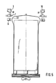
- the entire device is shown shortly before the shrinking is completed.
- the upper edge 22 of the film hood has entered the area where heat is applied.
- the suction devices 3 switch over to pressure operation, while at the same time their pipe sections 10 are pivoted slightly obliquely downwards.
- the compressed air jets create a slight negative pressure above the film hood, so that the hood cover, as shown in FIG. 5, rises somewhat. This enables largely contact-free heating even in the upper area of the film hood, which can also shrink freely when cooling.
- the present invention allows the heat application zone to be designed largely in its direction of movement according to the requirements.
- the direction of movement can also be carried out from top to bottom if, for example, the stack of goods has been placed from the start in a tubular bag which is closed at the bottom.
- the same prerequisites would be met by a stack of goods provided with an overlaid film hood, which has a closure at the bottom through a film cover sheet.
- Such closures on the underside of the stack of goods would also not allow air to be blown in, as was the case according to the prior art mentioned, so that a temporary air cushion could not be formed here in the conventional way.
- the proposal according to the invention is independent of a blowing-in of the known type.
- the method according to the invention can also be used if a further protective hood has to be pulled over the stack of goods covered with a film hood, for example for shielding against radiation.
- a further protective hood has to be pulled over the stack of goods covered with a film hood, for example for shielding against radiation.
- only the outer film hood is grasped by the lift-off during the vertical movement of the heat application zone from top to bottom or from bottom to top.
Landscapes
- Engineering & Computer Science (AREA)
- Mechanical Engineering (AREA)
- Basic Packing Technique (AREA)
- Laminated Bodies (AREA)
- Non-Metallic Protective Coatings For Printed Circuits (AREA)
- Lining Or Joining Of Plastics Or The Like (AREA)
Priority Applications (4)
| Application Number | Priority Date | Filing Date | Title |
|---|---|---|---|
| DE8787104515T DE3773371D1 (de) | 1987-03-26 | 1987-03-26 | Verfahren und vorrichtung zum aufschrumpfen einer auf einem palettierten gutstapel befindlichen folienhaube. |
| AT87104515T ATE67727T1 (de) | 1987-03-26 | 1987-03-26 | Verfahren und vorrichtung zum aufschrumpfen einer auf einem palettierten gutstapel befindlichen folienhaube. |
| ES198787104515T ES2026858T3 (es) | 1987-03-26 | 1987-03-26 | Procedimiento y dispositivo para la retraccion de una lamina de envoltura. |
| EP87104515A EP0283541B1 (fr) | 1987-03-26 | 1987-03-26 | Procédé et appareil pour rétrécir une housse en plastique autour d'une charge palettisée |
Applications Claiming Priority (1)
| Application Number | Priority Date | Filing Date | Title |
|---|---|---|---|
| EP87104515A EP0283541B1 (fr) | 1987-03-26 | 1987-03-26 | Procédé et appareil pour rétrécir une housse en plastique autour d'une charge palettisée |
Publications (2)
| Publication Number | Publication Date |
|---|---|
| EP0283541A1 true EP0283541A1 (fr) | 1988-09-28 |
| EP0283541B1 EP0283541B1 (fr) | 1991-09-25 |
Family
ID=8196873
Family Applications (1)
| Application Number | Title | Priority Date | Filing Date |
|---|---|---|---|
| EP87104515A Expired - Lifetime EP0283541B1 (fr) | 1987-03-26 | 1987-03-26 | Procédé et appareil pour rétrécir une housse en plastique autour d'une charge palettisée |
Country Status (4)
| Country | Link |
|---|---|
| EP (1) | EP0283541B1 (fr) |
| AT (1) | ATE67727T1 (fr) |
| DE (1) | DE3773371D1 (fr) |
| ES (1) | ES2026858T3 (fr) |
Cited By (7)
| Publication number | Priority date | Publication date | Assignee | Title |
|---|---|---|---|---|
| EP0649791A1 (fr) * | 1993-10-26 | 1995-04-26 | Maschinenfabrik Möllers GmbH u. Co. | Méthode et dispositif pour rétrécir une enveloppe à film rétrécissable |
| EP0657356A1 (fr) * | 1993-12-13 | 1995-06-14 | Kurt Lachenmeier A/S | Procédé et dispositif pour rétracter und housse en matériau thermorétractable sur une charge palletisée |
| EP0678452A1 (fr) * | 1994-04-22 | 1995-10-25 | Newtec International | Machine et procédé d'emballage d'une charge palettisée à l'aide d'une gaine thermorétractable |
| EP1000858A1 (fr) * | 1998-11-05 | 2000-05-17 | Kurt Lachenmeier A/S | Proçédé et dispositif pour appliquer et rétracter une housse d'emballage sur un objet |
| US6837031B1 (en) | 1999-01-28 | 2005-01-04 | MSK-Verpackungss-Systeme Gesellschaft Mit Beschrankter Haftung | Device for shrinking a shrink-wrap film |
| CN105253384A (zh) * | 2015-11-11 | 2016-01-20 | 中银(宁波)电池有限公司 | 电池塑料包装热收缩设备 |
| CN110834771A (zh) * | 2019-11-22 | 2020-02-25 | 安徽永锋智能包装科技有限公司 | 冰箱透明包装套袋收底方法 |
Citations (2)
| Publication number | Priority date | Publication date | Assignee | Title |
|---|---|---|---|---|
| EP0116124A1 (fr) * | 1982-12-30 | 1984-08-22 | MSK-Verpackungs-Systeme Gesellschaft mit beschränkter Haftung | Procédé et dispositif pour la rétraction d'une housse rétractable qui est tirée au dessus d'une pile d'articles |
| EP0205135A1 (fr) * | 1985-06-14 | 1986-12-17 | MSK-Verpackungs-Systeme Gesellschaft mit beschränkter Haftung | Procédé d'emballage d'une pile d'articles déposée sur une palette et dispositif pour la mise en oeuvre du procédé |
-
1987
- 1987-03-26 EP EP87104515A patent/EP0283541B1/fr not_active Expired - Lifetime
- 1987-03-26 ES ES198787104515T patent/ES2026858T3/es not_active Expired - Lifetime
- 1987-03-26 DE DE8787104515T patent/DE3773371D1/de not_active Revoked
- 1987-03-26 AT AT87104515T patent/ATE67727T1/de not_active IP Right Cessation
Patent Citations (2)
| Publication number | Priority date | Publication date | Assignee | Title |
|---|---|---|---|---|
| EP0116124A1 (fr) * | 1982-12-30 | 1984-08-22 | MSK-Verpackungs-Systeme Gesellschaft mit beschränkter Haftung | Procédé et dispositif pour la rétraction d'une housse rétractable qui est tirée au dessus d'une pile d'articles |
| EP0205135A1 (fr) * | 1985-06-14 | 1986-12-17 | MSK-Verpackungs-Systeme Gesellschaft mit beschränkter Haftung | Procédé d'emballage d'une pile d'articles déposée sur une palette et dispositif pour la mise en oeuvre du procédé |
Cited By (9)
| Publication number | Priority date | Publication date | Assignee | Title |
|---|---|---|---|---|
| EP0649791A1 (fr) * | 1993-10-26 | 1995-04-26 | Maschinenfabrik Möllers GmbH u. Co. | Méthode et dispositif pour rétrécir une enveloppe à film rétrécissable |
| EP0657356A1 (fr) * | 1993-12-13 | 1995-06-14 | Kurt Lachenmeier A/S | Procédé et dispositif pour rétracter und housse en matériau thermorétractable sur une charge palletisée |
| EP0678452A1 (fr) * | 1994-04-22 | 1995-10-25 | Newtec International | Machine et procédé d'emballage d'une charge palettisée à l'aide d'une gaine thermorétractable |
| FR2719019A1 (fr) * | 1994-04-22 | 1995-10-27 | Newtec Int | Procédé d'emballage d'une charge à l'aide d'une gaine thermorétractable et machine d'emballage mettant en Óoeuvre un tel procédé. |
| EP1000858A1 (fr) * | 1998-11-05 | 2000-05-17 | Kurt Lachenmeier A/S | Proçédé et dispositif pour appliquer et rétracter une housse d'emballage sur un objet |
| US6298636B1 (en) | 1998-11-05 | 2001-10-09 | Kl-Lachenmeier A/S | Method and apparatus for packaging an object |
| US6837031B1 (en) | 1999-01-28 | 2005-01-04 | MSK-Verpackungss-Systeme Gesellschaft Mit Beschrankter Haftung | Device for shrinking a shrink-wrap film |
| CN105253384A (zh) * | 2015-11-11 | 2016-01-20 | 中银(宁波)电池有限公司 | 电池塑料包装热收缩设备 |
| CN110834771A (zh) * | 2019-11-22 | 2020-02-25 | 安徽永锋智能包装科技有限公司 | 冰箱透明包装套袋收底方法 |
Also Published As
| Publication number | Publication date |
|---|---|
| ATE67727T1 (de) | 1991-10-15 |
| EP0283541B1 (fr) | 1991-09-25 |
| DE3773371D1 (de) | 1991-10-31 |
| ES2026858T3 (es) | 1992-05-16 |
Similar Documents
| Publication | Publication Date | Title |
|---|---|---|
| EP0133462B1 (fr) | Procédé pour l'emballage de piles de marchandises palettisées et dispositif pour la mise en oeuvre du procédé | |
| DE4103384C2 (de) | Vorrichtung zum Überziehen von Stretchfolienhauben über einen Gutstapel | |
| EP1000858B1 (fr) | Proçédé et dispositif pour appliquer et rétracter une housse d'emballage sur un objet | |
| EP0077508B1 (fr) | Procédé et dispositif d'emballage de piles d'objets palettisés | |
| DE3242677C2 (fr) | ||
| EP2825468B1 (fr) | Dispositif et procédé destinés à emmancher une feuille d'emballage sur une pile de marchandises | |
| EP0376028B1 (fr) | Dispositif d'emballage pour une pile d'articles posée sur une palette | |
| EP0250647A1 (fr) | Installation pour envelopper une charge d'une housse en feuille de rétraction et pour la rétrécir autour de ladite charge | |
| EP0283541B1 (fr) | Procédé et appareil pour rétrécir une housse en plastique autour d'une charge palettisée | |
| EP1050466A1 (fr) | Procede et appareil pour emballer des articles dans un film retractable | |
| WO2007048558A1 (fr) | Procédé et dispositif de rétrécissement d’une feuille thermorétractile disposée autour d’une pile de marchandises, en particulier en palettes | |
| EP3381816B1 (fr) | Procédé de création d'au moins un espace libre dans une enveloppe comprenant une feuille étirable, qui immobilise une pile de produits disposés sur une palette et dispositif de façonnage destiné à exécuter le procédé | |
| EP0205135B1 (fr) | Procédé d'emballage d'une pile d'articles déposée sur une palette et dispositif pour la mise en oeuvre du procédé | |
| EP0294567B1 (fr) | Appareil pour rétrécir une housse contractile enveloppant une charge palettisée | |
| EP4559826A1 (fr) | Dispositif pour rétracter une feuille thermorétractable autour d'une pile de marchandises, de préférence palettisée et procédé pour rétracter une pile de marchandises | |
| EP0649791A1 (fr) | Méthode et dispositif pour rétrécir une enveloppe à film rétrécissable | |
| EP0378730B1 (fr) | Appareil pour emballer des objets avec une bande tubulaire en matière plastique | |
| EP0493641A1 (fr) | Procédé et dispositif pour emballer des objets dans une housse tubulaire en matière plastique | |
| EP0933297B2 (fr) | Procédé et dispositif pour emballer une charge | |
| EP0579858B1 (fr) | Procédé et dispositif pour l'emballage de marchandises empilées | |
| DE9310218U1 (de) | Vorrichtung zum Schrumpfen einer über einen Gutstapel gezogenen Schrumpfhaube | |
| DE4342490C2 (de) | Verfahren und Vorrichtung zum Schrumpfen einer aus heißschrumpffähigem Material bestehenden Folienhaube, die über eine auf einer Palette befindliche Ladung gezogen ist | |
| EP0030346B1 (fr) | Dispositif de rétraction de housses rétractables enveloppant des piles d'objets | |
| DE3141100A1 (de) | Verfahren und vorrichtung zum verpacken von plaettierten gutstapeln | |
| EP0631935A1 (fr) | Dispositif pour rétrécir une feuille d'emballage sur une unité d'emballage |
Legal Events
| Date | Code | Title | Description |
|---|---|---|---|
| PUAI | Public reference made under article 153(3) epc to a published international application that has entered the european phase |
Free format text: ORIGINAL CODE: 0009012 |
|
| AK | Designated contracting states |
Kind code of ref document: A1 Designated state(s): AT BE CH DE ES FR GB GR IT LI LU NL SE |
|
| 17P | Request for examination filed |
Effective date: 19881130 |
|
| 17Q | First examination report despatched |
Effective date: 19900717 |
|
| GRAA | (expected) grant |
Free format text: ORIGINAL CODE: 0009210 |
|
| RAP3 | Party data changed (applicant data changed or rights of an application transferred) |
Owner name: VFI GESELLSCHAFT FUER VERPACKUNGSTECHNIK MBH |
|
| AK | Designated contracting states |
Kind code of ref document: B1 Designated state(s): AT BE CH DE ES FR GB GR IT LI LU NL SE |
|
| PG25 | Lapsed in a contracting state [announced via postgrant information from national office to epo] |
Ref country code: SE Effective date: 19910925 |
|
| REF | Corresponds to: |
Ref document number: 67727 Country of ref document: AT Date of ref document: 19911015 Kind code of ref document: T |
|
| REF | Corresponds to: |
Ref document number: 3773371 Country of ref document: DE Date of ref document: 19911031 |
|
| ITF | It: translation for a ep patent filed | ||
| PG25 | Lapsed in a contracting state [announced via postgrant information from national office to epo] |
Ref country code: GR Free format text: LAPSE BECAUSE OF FAILURE TO SUBMIT A TRANSLATION OF THE DESCRIPTION OR TO PAY THE FEE WITHIN THE PRESCRIBED TIME-LIMIT Effective date: 19911227 |
|
| GBT | Gb: translation of ep patent filed (gb section 77(6)(a)/1977) | ||
| ET | Fr: translation filed | ||
| REG | Reference to a national code |
Ref country code: ES Ref legal event code: FG2A Ref document number: 2026858 Country of ref document: ES Kind code of ref document: T3 |
|
| PLBI | Opposition filed |
Free format text: ORIGINAL CODE: 0009260 |
|
| 26 | Opposition filed |
Opponent name: MSK-VERPACKUNGS-SYSTEME GMBH Effective date: 19920617 |
|
| NLR1 | Nl: opposition has been filed with the epo |
Opponent name: MSK-VERPACKUNGS-SYSTEME GMBH |
|
| PGFP | Annual fee paid to national office [announced via postgrant information from national office to epo] |
Ref country code: GB Payment date: 19930305 Year of fee payment: 7 |
|
| PGFP | Annual fee paid to national office [announced via postgrant information from national office to epo] |
Ref country code: FR Payment date: 19930315 Year of fee payment: 7 Ref country code: ES Payment date: 19930315 Year of fee payment: 7 |
|
| PGFP | Annual fee paid to national office [announced via postgrant information from national office to epo] |
Ref country code: LU Payment date: 19930324 Year of fee payment: 7 |
|
| PGFP | Annual fee paid to national office [announced via postgrant information from national office to epo] |
Ref country code: AT Payment date: 19930330 Year of fee payment: 7 |
|
| PGFP | Annual fee paid to national office [announced via postgrant information from national office to epo] |
Ref country code: NL Payment date: 19930331 Year of fee payment: 7 |
|
| PGFP | Annual fee paid to national office [announced via postgrant information from national office to epo] |
Ref country code: BE Payment date: 19930406 Year of fee payment: 7 |
|
| PGFP | Annual fee paid to national office [announced via postgrant information from national office to epo] |
Ref country code: CH Payment date: 19930419 Year of fee payment: 7 |
|
| PGFP | Annual fee paid to national office [announced via postgrant information from national office to epo] |
Ref country code: DE Payment date: 19930518 Year of fee payment: 7 |
|
| EPTA | Lu: last paid annual fee | ||
| RDAG | Patent revoked |
Free format text: ORIGINAL CODE: 0009271 |
|
| STAA | Information on the status of an ep patent application or granted ep patent |
Free format text: STATUS: PATENT REVOKED |
|
| 27W | Patent revoked |
Effective date: 19930523 |
|
| GBPR | Gb: patent revoked under art. 102 of the ep convention designating the uk as contracting state |
Free format text: 930523 |
|
| REG | Reference to a national code |
Ref country code: CH Ref legal event code: PL |
|
| NLR2 | Nl: decision of opposition |