EP4559826A1 - Dispositif pour rétracter une feuille thermorétractable autour d'une pile de marchandises, de préférence palettisée et procédé pour rétracter une pile de marchandises - Google Patents
Dispositif pour rétracter une feuille thermorétractable autour d'une pile de marchandises, de préférence palettisée et procédé pour rétracter une pile de marchandises Download PDFInfo
- Publication number
- EP4559826A1 EP4559826A1 EP24213828.7A EP24213828A EP4559826A1 EP 4559826 A1 EP4559826 A1 EP 4559826A1 EP 24213828 A EP24213828 A EP 24213828A EP 4559826 A1 EP4559826 A1 EP 4559826A1
- Authority
- EP
- European Patent Office
- Prior art keywords
- shrink
- hood
- nozzle
- frame
- shrinking
- Prior art date
- Legal status (The legal status is an assumption and is not a legal conclusion. Google has not performed a legal analysis and makes no representation as to the accuracy of the status listed.)
- Pending
Links
Images




Classifications
-
- B—PERFORMING OPERATIONS; TRANSPORTING
- B65—CONVEYING; PACKING; STORING; HANDLING THIN OR FILAMENTARY MATERIAL
- B65B—MACHINES, APPARATUS OR DEVICES FOR, OR METHODS OF, PACKAGING ARTICLES OR MATERIALS; UNPACKING
- B65B53/00—Shrinking wrappers, containers, or container covers during or after packaging
- B65B53/02—Shrinking wrappers, containers, or container covers during or after packaging by heat
- B65B53/06—Shrinking wrappers, containers, or container covers during or after packaging by heat supplied by gases, e.g. hot-air jets
- B65B53/066—Mobile frames, hoods, posts or the like
-
- B—PERFORMING OPERATIONS; TRANSPORTING
- B65—CONVEYING; PACKING; STORING; HANDLING THIN OR FILAMENTARY MATERIAL
- B65B—MACHINES, APPARATUS OR DEVICES FOR, OR METHODS OF, PACKAGING ARTICLES OR MATERIALS; UNPACKING
- B65B53/00—Shrinking wrappers, containers, or container covers during or after packaging
- B65B53/02—Shrinking wrappers, containers, or container covers during or after packaging by heat
- B65B53/06—Shrinking wrappers, containers, or container covers during or after packaging by heat supplied by gases, e.g. hot-air jets
-
- B—PERFORMING OPERATIONS; TRANSPORTING
- B65—CONVEYING; PACKING; STORING; HANDLING THIN OR FILAMENTARY MATERIAL
- B65B—MACHINES, APPARATUS OR DEVICES FOR, OR METHODS OF, PACKAGING ARTICLES OR MATERIALS; UNPACKING
- B65B9/00—Enclosing successive articles, or quantities of material, e.g. liquids or semiliquids, in flat, folded, or tubular webs of flexible sheet material; Subdividing filled flexible tubes to form packages
- B65B9/10—Enclosing successive articles, or quantities of material, in preformed tubular webs, or in webs formed into tubes around filling nozzles, e.g. extruded tubular webs
- B65B9/13—Enclosing successive articles, or quantities of material, in preformed tubular webs, or in webs formed into tubes around filling nozzles, e.g. extruded tubular webs the preformed tubular webs being supplied in a flattened state
- B65B9/135—Enclosing successive articles, or quantities of material, in preformed tubular webs, or in webs formed into tubes around filling nozzles, e.g. extruded tubular webs the preformed tubular webs being supplied in a flattened state for palletised loads
Definitions
- the invention relates to a device for shrinking a heat-shrink film placed around a preferably palletized stack of goods, with a shrink frame which is movable on a frame in the vertical direction between an upper position and a lower position and forms a recess for the stack of goods, on which shrink frame at least one shrinking device is provided for shrinking the heat-shrink film by heating, wherein the device has a shrink hood which forms a shrink space above the shrink frame and is open downwards, comprising a circumferential side wall and a lid, wherein the shrink hood is movable in the vertical direction and wherein the device further has at least one blower which generates an air flow in the interior of the shrink hood, wherein the at least one blower has an impeller driven by a drive.
- Devices for shrinking a heat-shrink film wrapped around a stack of goods are known in practice. These devices include a shrink hood. A fan circulates the air inside the shrink hood to achieve a uniform temperature level within the shrink hood. The fan only allows for the circulation of the air inside the shrink hood.
- the object of the invention is to avoid the aforementioned disadvantage and to provide a device which enables a more targeted application of heat to individual areas of the heat shrink film inside the shrink hood.
- At least one air guide section is connected to the impeller of at least one fan, which air guide section has at least one nozzle at its end opposite the impeller, so that the air sucked in by the impeller in the shrink space enclosed by the shrink hood can be directed back into the shrink space enclosed by the shrink hood via the at least one nozzle.
- Each air duct section connected to the impeller and having at least one nozzle forms an air channel through which the heated air drawn in by the fan flows.
- the nozzle focuses the air flow generated by the respective fan onto a specific area of the heat shrink film.
- the heated air is taken by the fan from the heated shrink space above the stack of goods and, after flowing through the air duct section, is blown out in a targeted and therefore directed manner.
- the direction of the air flow is used specifically to heat individual areas of the heat shrink film on the surface of the stack of goods and thus shrink the corresponding area of the heat shrink film.
- the focus is particularly on areas where several film layers are to be joined. These could be areas where a jacket film and a cover sheet film overlap, for example. In this way, good packaging with high load stability of the packaged goods is achieved.
- the air is sucked in by the impeller from the area above the stack of goods and blown back into the shrinking space enclosed by the shrink hood via at least one nozzle.
- the shrink frame and thus also the shrink hood are in the upper position.
- the shrink chamber is heated by the shrink device(s).
- the stack of goods, along with the heat shrink film already in place and any cover film applied is transported forward using a conveyor, for example, until the stack of goods is centered beneath the shrink frame and shrink hood.
- the shrink frame and thus also the shrink hood are then moved vertically downwards to their lower position.
- the shrink hood, with its heated shrink chamber lowers over the stack of goods.
- An air stream, generated by the respective fan is directed through each nozzle onto the desired surface section of the stack of goods.
- the shrink frame and shrink hood have reached their lower position, the shrinking process is complete.
- the shrink frame and shrink hood are moved back to their upper position and the stack of goods, with the shrunk-out heat shrink film, is conveyed away.
- the shrink frame typically consists of four frame sections forming a square recess.
- the shrink space encompassed by the shrink hood is enlarged by the shrink frame arranged below the shrink hood.
- the shrink hood is preferably connected directly to the shrink frame, for example to the top of the shrink frame, or placed on top of the shrink frame.
- the shrink hood and shrink frame can be connected to one another in an airtight manner.
- the shrink hood preferably consists of a thermally insulated housing.
- the at least one shrink device can, for example, be designed as an electrically operated shrink device. Other types of shrink device are also possible.
- the shrink device can also be gas-operated.
- the drive of each fan is located outside the shrink-wrap hood, while the impeller is located inside the hood.
- This arrangement saves space inside the shrink-wrap hood.
- the drive is not exposed to the high operating temperatures inside the shrink-wrap hood.
- the entire fan it is also possible for the entire fan to be located inside the shrink hood. However, it is also conceivable for the fan to be located outside the shrink hood, and for the air to be extracted from the interior of the shrink hood through an opening in the cover. An air duct section can be located inside or outside the shrink hood.
- At least one nozzle can be designed as a slot nozzle.
- the slot nozzle preferably extends from one side to the opposite side of the shrink hood and thus over the entire edge of a stack of goods to be shrunk. This allows the edge to be heated evenly along its entire length.
- a slot nozzle creates a linear blow-out jet that can be optimally directed, for example, onto an edge. The heated air is not directed merely onto a specific area of the heat-shrink film, but rather over the entire length of the edge of the stack of goods.
- At least one fan can be designed as a radial fan. This design allows the fan, or at least the fan impeller, to be arranged inside the shrink hood, even when the available installation space is limited.
- the impeller of at least one fan and the air duct section extending from this impeller can be mounted below the cover of the shrink hood or directly or indirectly on the inside of the cover of the shrink hood.
- the impeller below the cover of the shrink hood, the particularly warm air in the upper area of the shrink hood, i.e., below the cover, can be extracted and then directed back into the air.
- At least one heating element can be provided in at least one air guide section for heating the air flowing through this air guide section.
- the heating element can heat the air flowing through this air guide section to the temperature required for shrinkage.
- the heating element connected to this air guide section connected nozzle, air with a higher temperature than the temperature generally present inside the shrink hood can be directed specifically onto the heat shrink film.
- the assembly consisting of the impeller, the air guide section, and the at least one nozzle can be designed to be horizontally movable. In such a configuration, the entire assembly is displaced horizontally.
- the at least one nozzle can be designed to be horizontally movable, and the length of the air guide section can be varied according to the respective position of the at least one nozzle.
- the nozzle can, for example, be arranged on a carriage that can be moved along at least one rail.
- a drive such as a linear drive, can be assigned to the carriage.
- the air guide section is either flexible, for example, as a hose, or at least length-flexible, for example, telescopic.
- At least one nozzle in at least one blower can be vertically movable.
- the nozzle can be arranged, for example, on a carriage that can be moved along a rail.
- a drive preferably a linear drive, can be assigned to the carriage.
- the air guide section and the impeller are not also vertically movable together with the nozzle, the air guide section can be flexible, for example, as a hose, or flexible in length, for example, telescopic.
- At least one nozzle can be arranged in at least one blower so that it can pivot about a horizontal axis.
- This nozzle can be pivoted by means of a drive, for example a pneumatic or electric drive. This allows the nozzle in question to be optimally aligned to an edge of a stack of goods, even with different dimensions. This proves to be advantageous when an increased amount of heat is required to shrink several layers at one edge.
- the device can have a closure surface whose contour and dimensions are adapted to the contour and dimensions of the recess in the shrink frame in such a way that the closure surface, on the one hand, and the shrink frame and the shrink hood, on the other hand, are movable relative to one another.
- the closure surface When the shrink frame is in its upper position, the closure surface is arranged within the recess, preferably in a stationary manner, so that the closure surface comes closer to the cover of the shrink hood as the shrink frame is increasingly moved into its lower position.
- the closure surface has feet, for example, and rests on the floor at its bottom. Alternatively, it can be attached to a crossbeam of the frame, for example by means of rods. In this case, the rods extend through the cover of the shrink hood.
- the closure surface is adapted to the recess in terms of its contour and dimensions in such a way that a gap remains between the outer edge of the closure surface and the inner edge of the recess, so that the closure surface can move relative to the recess, preferably without contact.
- the sealing surface reduces heat loss when the shrink frame is in its upper position.
- the sealing surface is positioned at a height that, on the one hand, is above the stack of goods and, on the other hand, essentially seals the shrink frame at its bottom.
- the sealing surface thus allows the recess of the shrink frame and thus the shrink space of the shrink hood to be almost completely sealed, except for the area of the previously described gap.
- the shrink hood can be connected to the shrink frame, preferably in an airtight manner.
- the shrink hood is vertically displaced together with the shrink frame.
- Connection is understood, for example, to mean a configuration in which the shrink hood is directly attached to the shrink frame, for example, by screwing, riveting, or welding.
- Connection is also understood, for example, to mean a variant in which, for example, sections of the shrink frame also form the side parts of the shrink hood.
- the shrink hood can advantageously be connected to the shrink frame in an airtight manner.
- the impeller can be surrounded by a housing having an intake opening, with at least one ventilation section adjoining the housing.
- the invention also relates to a method for shrinking a heat-shrink film placed around a preferably palletized stack of goods, preferably using a device with a shrink frame which is movable on a frame in the vertical direction between an upper position and a lower position and forms a recess for the stack of goods, on which shrink frame at least one shrink device is provided for shrinking the heat-shrink film by heating, wherein the device has a downwardly open shrink hood which forms a shrink space above the shrink frame and comprises a circumferential side wall and a lid, wherein the shrink hood is moved in the vertical direction, and wherein the device further has at least one blower which generates an air flow in the interior of the shrink hood, wherein the at least one blower has an impeller driven by a drive, particularly preferably using a device according to one of the previously described embodiments.
- Devices for shrinking a heat-shrink film wrapped around a stack of goods are known in practice. These devices include a shrink hood. A fan circulates the air inside the shrink hood to achieve a uniform temperature level within the shrink hood. The fan only allows for the circulation of the air inside the shrink hood.
- the object of the invention is to avoid the aforementioned disadvantage and to provide a method which enables a more targeted application of heat to individual areas of the heat shrink film inside the shrink hood.
- At least one air guide section is connected to the impeller of at least one fan, which air guide section has at least one nozzle at its end opposite the impeller, so that the air sucked in by the impeller in the shrink space enclosed by the shrink hood is directed back into the shrink space enclosed by the shrink hood via the at least one nozzle.
- the nozzle focuses the air flow generated by the respective fan onto a specific area of the heat-shrink film.
- the heated air is taken by the fan from the heated shrink space above the stack of goods and, after flowing through the air guide section, is blown out in a targeted and thus directed manner.
- the direction of the air flow is used specifically to heat individual areas of the heat-shrink film on the surface of the stack of goods and thus shrink the corresponding area of the heat-shrink film.
- the focus is particularly on areas where several film layers are to be joined. These can be, for example, areas where a jacket film and a cover sheet film overlap. In this way, good packaging with high load stability of the packaged goods is achieved.
- the air is drawn by the impeller from the area above the stack of goods. sucked in and blown back into the shrink space enclosed by the shrink hood via at least one nozzle.
- the shrink frame and thus also the shrink hood are in the upper position.
- the shrink chamber is heated by the shrink device(s).
- the stack of goods with the heat shrink film already provided and any cover film applied is transported forward, for example by means of a conveyor, until the stack of goods is centered below the shrink frame and the shrink hood.
- the shrink frame and thus also the shrink hood are then moved vertically downwards to their lower position.
- the shrink hood with the heated shrink chamber is lowered over the stack of goods.
- An air stream, generated by the respective fan is directed through each nozzle onto the desired surface section of the stack of goods.
- the shrink frame typically consists of four frame sections forming a square recess.
- the shrink space encompassed by the shrink hood is enlarged by the shrink frame arranged below the shrink hood.
- the shrink hood is preferably connected directly to the shrink frame, for example to the top of the shrink frame, or placed on top of the shrink frame.
- the shrink hood and shrink frame can be connected to one another in an airtight manner.
- the shrink hood preferably consists of a thermally insulated housing.
- the at least one shrink device can, for example, be designed as an electrically operated shrink device. Other types of shrink device are also possible.
- the shrink device can also be gas-operated.
- the drive of each fan is located outside the shrink-wrap hood, while the impeller is located inside the hood.
- This arrangement saves space inside the shrink-wrap hood.
- the drive is not exposed to the high operating temperatures inside the shrink-wrap hood.
- the entire fan it is also possible for the entire fan to be located inside the shrink hood. However, it is also conceivable for the fan to be located outside the shrink hood, and for the air to be extracted from the interior of the shrink hood through an opening in the cover. An air duct section can be located inside or outside the shrink hood.
- the air sucked in by the impeller in the shrink space enclosed by the shrink hood can be directed back into the shrink space enclosed by the shrink hood via the at least one nozzle designed as a slotted nozzle.
- the slotted nozzle preferably extends from one side to the opposite side of the shrink hood and thus over the entire edge of a stack of goods to be shrunk. This allows the edge to be heated evenly over its entire length.
- a slotted nozzle creates a linear blow-out jet that can be optimally directed, for example, onto an edge. The heated air is not just directed onto a specific area of the heat shrink film, but over the entire length of the edge of the stack of goods.
- the assembly consisting of the impeller, the air guide section, and the at least one nozzle can be moved horizontally. In such a configuration, the entire assembly is displaced horizontally.
- the at least one nozzle can be moved horizontally and the length of the air guide section can be varied according to the respective position of the at least one nozzle.
- the nozzle can, for example, be arranged on a carriage which is guided along at least one The carriage can be moved along a rail.
- a drive such as a linear drive, can be assigned to the carriage.
- the air guide section is either flexible, for example, as a hose, or at least flexible in length, for example, telescopic.
- At least one nozzle in at least one blower can be moved vertically.
- the nozzle can be arranged, for example, on a carriage that can be moved along a rail.
- a drive preferably a linear drive, can be assigned to the carriage. If the air guide section and the impeller cannot also be moved vertically together with the nozzle, the air guide section can be designed to be flexible, for example, as a hose, or to be length-flexible, for example, telescopic.
- At least one nozzle can be pivoted around a horizontal axis with at least one blower.
- This nozzle can be pivoted using a drive, such as a pneumatic or electric drive. This allows the nozzle in question to be optimally aligned to an edge of a stack of goods, even with different dimensions. This proves to be advantageous when a higher amount of heat is required in the area of an edge to shrink multiple layers.
- At least one heating element can be provided in at least one air guide section, and at least one heating element can heat the air flowing through this air guide section.
- the heating element can heat the air flowing through this air guide section to the temperature required for shrinking.
- air at a higher temperature than the temperature generally present inside the shrink hood can be directed specifically onto the heat-shrink film through the nozzle connected to this air guide section.
- the device can have a closure surface which is adapted in terms of its contour and dimensions to the contour and dimensions of the recess of the shrink frame in such a way that the The closure surface, on the one hand, and the shrink frame and the shrink hood, on the other hand, are moved relative to one another, the closure surface being arranged, preferably stationary, within the recess when the shrink frame is in its upper position, so that the closure surface comes closer to the cover of the shrink hood as the shrink frame is increasingly moved into its lower position.
- the closure surface has feet, for example, and rests on the floor at its bottom. Alternatively, it can be attached to a cross member of the frame, for example by means of rods. In this case, the rods extend through the cover of the shrink hood.
- the closure surface is adapted to the recess in terms of its contour and dimensions in such a way that a gap remains between the outer edge of the closure surface and the inner edge of the recess so that the closure surface can move relative to the recess, preferably without contact.
- the closure surface reduces heat losses when the shrink frame is in its upper position.
- the sealing surface is positioned at a height such that, on the one hand, it is above the stack of goods and, on the other hand, it essentially seals the underside of the shrink frame. The sealing surface thus allows the recess of the shrink frame and thus the shrink space of the shrink hood to be almost completely sealed, except for the area of the previously described gap. By closing the shrink hood or shrink frame, the energy consumption of the device can be significantly reduced.
- the distance A between the top of the stack of goods and the cover of the shrink hood can be at least 300 mm. Due to the remaining distance A of at least 300 mm between the top of the stack of goods and the underside of the cover in the lower position of the shrink frame and shrink hood, each impeller can easily suck in the air contained in the shrink space enclosed by the shrink hood and, via at least one nozzle, direct it back into the shrink space enclosed by the shrink hood by blowing it in.
- At least one nozzle preferably designed as a slotted nozzle, can be directed toward the adjacent upper edge of the stack of goods.
- heat can be applied specifically to the area of the heat-shrink film that extends along the respective edge. This enables, for example, optimal welding of the edge area of a heat-shrink band to a cover film placed on the stack of goods.
- an air stream is directed via at least two opposing nozzles onto two opposite upper edges of the stack of goods.
- This method applies heat simultaneously and in a targeted manner to the two opposite edges of a stack of goods. These edges are preferably the two long edges of a stack of goods. If the stacks of goods are conveyed to the device, for example, by a conveyor belt and away from it after shrinking, the two long edges are aligned parallel to the transport direction of the stack of goods.
- At least one nozzle can be set into a pendulum motion around its horizontal axis.
- This mode of operation is suitable, for example, when a heat-shrink hood is used as the heat-shrink film.
- the pendulum motion allows the air flow to be directed more evenly from the edge toward the opposite edge of the top of the stack of goods.
- the Fig. 1 shows a device 1 for shrinking a heat-shrink film 3 (not shown) placed around a stack of goods 2 (also not shown).
- the device 1 comprises a frame 4 with a shrink frame 5 which can be moved vertically between an upper position and a lower position.
- the shrink frame 5 consists of four frame parts forming a square recess 19.
- a shrinking device (not shown in this figure) for shrinking the heat-shrink film 3 by heating is provided on each frame part.
- the device 1 also comprises a downwardly open shrink hood 6 forming a shrink space above the shrink frame 5.
- the shrink hood 6 is designed with a circumferential side wall 7 and a cover 8.
- the shrink hood 6 is connected to the shrink frame 5 and thus forms a unit with the shrink frame 5.
- the device 1 further comprises two fans 9, each generating an air flow inside the shrink hood 6, each having an impeller 20 driven by a drive 10.
- each impeller 20 of each fan 9 is located inside the shrink-wrap hood 6, while the respective drive 10 is arranged on the outside of the shrink-wrap hood 6.
- each impeller 20 is surrounded by a housing 21, each housing 21 having an intake opening 22 on its underside.
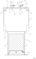
- Fig. 2 shows a sectional view of the object according to Fig. 1
- the shrink hood 6 is hermetically connected to the shrink frame 5.
- the shrink frame 5 is in its upper position.
- the shrink frame 5 forms the recess 19 for the stack of goods 2.
- the stack of goods 2 has a bottom side, by means of which the stack of goods 2 is placed on a pallet 23, four side surfaces, and a top side. Furthermore, the stack of goods 2 has an edge 17 at the transition from each side surface to the top side.
- the shrinking devices are arranged around the recess 19 and, in the illustrated embodiment, each has at least one obliquely downwardly directed slot-like blow-out nozzle 24 for blowing out heated air for shrinking the heat-shrink film 3.
- the frame 4 of the device 1 (not shown) is located behind the shrink hood 6 or the stack of goods 2 and rests on a base 15.
- the stack of goods 2 with the heat-shrink film 3 is shown centered under the shrink hood 6.
- the housings 21, each containing the impeller 20, are arranged on the inside of the cover 8.
- Each impeller 20, i.e., each housing 21, is connected to an air duct section 11.
- Each air duct section 11 has a nozzle 12 at its end opposite the impeller 20.
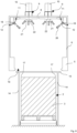
- Fig. 3 shows a further state of motion of the object according to Fig. 2
- the lower edge of the shrink frame 5 is now below the stack of goods 2 at the height of a pallet 23.
- the shrink frame 5 has been moved accordingly from its upper position to its lower position.
- the heated air blown out via the blower nozzles 24 shrinks the heat-shrink film 3 inside the shrink hood 6.
- the fans 9 simultaneously suck air in the direction of the arrows 25 from the upper area of the shrink space inside the shrink hood 6.
- the sucked-in air is then directed via the respective air guide section 11 through the nozzles 12 in the direction of the arrows 26 into the shrink space enclosed by the shrink hood 6.
- each of the two nozzles 12 is designed as a slot nozzle.
- the orientation of the slot nozzles is such that in the lower position of the shrink frame 5 the blown out air is blown in the direction of the arrows 26 onto the adjacent edges 17 of the stack of goods 2.
- the distance A between the top of the stack of goods 2 and the cover 8 of the shrink hood 6 is at least 300 mm.
- Fig. 4 shows a sectional view of a further embodiment of the device 1 according to the invention.
- the device 1 shown differs only in that it is Fig. 2
- the device 1 shown is characterized in that it has a closing surface 13 which, in terms of its contour and dimensions, is adapted to the contour and dimensions of the recess 19 of the shrink frame 5.
- the closing surface 13 on the one hand and the shrink frame 5 and the shrink hood 6 on the other hand are movable relative to one another.
- the shrink frame 5 forms the recess 19 for the stack of goods 2 and is in its upper position.
- the closing surface 13 is located within the recess 19 of the shrink frame 5 and is arranged such that the closing surface 13 comes closer to the cover 8 of the shrink hood 6 as the shrink frame 5 is increasingly moved into its lower position.
- the closing surface 13 has feet 14 and rests with these on the bottom 15.
- the closing surface 13 is adapted in terms of its contour and dimensions to the recess 19 such that a gap remains between the outer edge of the closing surface 13 and the inner edge of the recess 19.
- the closing surface 13 reduces heat losses when the shrink frame 5 is in its upper position.
- the closing surface 13 is also arranged at such a height that, on the one hand, it is above the stack of goods 2 and, on the other hand, essentially closes the shrink frame 5 on its underside. The closing surface 13 can thus almost completely close the recess 19 of the shrink frame 5 and thus the shrink space of the shrink hood 6, except in the area of the gap described above.
- each of the two nozzles 12 is designed as a slot nozzle.
- the alignment of the slot nozzles is such that, in the lower position of the shrink frame 5, the expelled air is blown in the direction of the arrows 26 onto the adjacent edges 17 of the stack of goods 2.
- the sealing surface 13 has shifted into the interior of the shrink hood 6.
- the feet 14 do not obstruct the air flow directed by the nozzles 12, as they are arranged such that they do not partially cover the respective slot nozzle.
- Fig. 6 shows a sectional view of a further embodiment of the device 1 according to the invention.
- the device 1 shown differs only in that it is Fig. 4 shown device 1, that the closing surface 13 is now suspended from rods 16, wherein the rods 16 are guided through the cover 8 of the shrink hood 6 and are in turn fastened to the frame 4.
- the frame 4 stands on the floor 15.
- the closing surface 13 on the one hand and the shrink frame 5 and the shrink hood 6 on the other hand are movable relative to one another.
- the shrink frame 5 forms the recess 19 for the stack of goods 2 and is in its upper position.
- the closing surface 13 is located within the recess 19 of the shrink frame 5 and is arranged such that the closing surface 13 comes closer to the cover 8 of the shrink hood 6 as the shrink frame 5 is increasingly moved into its lower position.
- Fig. 7 shows the position in which the lower edge of the shrink frame 5 is arranged lower than the underside of the stack of goods 2.
- the shrink frame 5 has been moved accordingly from its upper position to its lower position. This in turn is the start of the shrinking process in which the shrink frame 5 is moved vertically upwards.
- the air heated by the shrinking devices shrinks the heat-shrink film 3 inside the shrink hood 6.
- the fans 9 suck air from the upper area of the shrink space inside the shrink hood 6 in the direction of the arrow 25 and guide it via the respectively connected air guide section 11 to the nozzle 12.
- the warm air is blown back into the shrink space enclosed by the shrink hood 6 via the respective nozzle 12 in the direction of the arrows 26.
- each of the two nozzles 12 is designed as a slot nozzle.
- the alignment of the slot nozzles is such that in the lower position of the shrink frame 5 the blown-out air is blown in the direction of the arrows 26 onto the adjacent edges 17 of the stack of goods 2.
- Fig. 8 shows a sectional view of a further embodiment of the device 1 according to the invention.
- the device 1 shown differs only in that it is Fig. 4 that the nozzles 12 are arranged so as to be pivotable about a horizontal axis 18.
- Each nozzle 12 can be pivoted, for example, using an electric motor (not shown). Pivoting each nozzle 12 enables the precise alignment of each nozzle 12 to the respective edge 17 of a stack of goods 2. This adjustment can also take place during the vertical displacement of the shrink frame 5. This allows the edges 17 of stacks of goods 2 of different heights to be optimally shrunk.
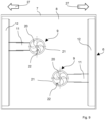
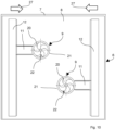
- Fig. 9 shows a view of the underside of the cover 8 of the shrink hood 6.
- Each of the two impellers 20 is surrounded by a housing 21, each housing 21 having the intake opening 22 on its underside.
- the air guide section 11 is connected to each impeller 20, i.e. to each housing 21.
- Each air guide section 11 has at its
- the nozzle 12 is located at the end opposite the impeller 20.
- Each nozzle 12 is designed as a slot nozzle.
- each air guide section 11 can be varied according to the respective position of the respective nozzle 12.
- each air guide section 11 can be designed to be telescopic. This allows the corresponding nozzle 12 to be moved horizontally in the direction of arrow 27, despite the fixed position of an impeller 20. This allows each nozzle 12 to be optimally positioned, for example, relative to the respective edge 17.
- the complete arrangement consisting of the impeller 20, the housing 21 located around it, the air guide section 11 and the nozzle 12 as a whole can be designed to be horizontally movable in the direction of the arrow 27.
Landscapes
- Engineering & Computer Science (AREA)
- Mechanical Engineering (AREA)
- Sealing Of Jars (AREA)
Applications Claiming Priority (1)
| Application Number | Priority Date | Filing Date | Title |
|---|---|---|---|
| DE202023106879.0U DE202023106879U1 (de) | 2023-11-22 | 2023-11-22 | Vorrichtung zum Schrumpfen einer um einen, vorzugsweise palettierten, Gutstapel gelegten Heißschrumpffolie |
Publications (1)
| Publication Number | Publication Date |
|---|---|
| EP4559826A1 true EP4559826A1 (fr) | 2025-05-28 |
Family
ID=90054953
Family Applications (1)
| Application Number | Title | Priority Date | Filing Date |
|---|---|---|---|
| EP24213828.7A Pending EP4559826A1 (fr) | 2023-11-22 | 2024-11-19 | Dispositif pour rétracter une feuille thermorétractable autour d'une pile de marchandises, de préférence palettisée et procédé pour rétracter une pile de marchandises |
Country Status (4)
| Country | Link |
|---|---|
| US (1) | US20250162753A1 (fr) |
| EP (1) | EP4559826A1 (fr) |
| CN (1) | CN120024559A (fr) |
| DE (1) | DE202023106879U1 (fr) |
Families Citing this family (1)
| Publication number | Priority date | Publication date | Assignee | Title |
|---|---|---|---|---|
| CN121084720B (zh) * | 2025-11-07 | 2026-01-09 | 常州市天方印刷有限公司 | 一种附带质量反馈功能的全自动打包装置 |
Citations (2)
| Publication number | Priority date | Publication date | Assignee | Title |
|---|---|---|---|---|
| EP0285855B1 (fr) * | 1987-03-11 | 1992-08-12 | Kurt Lachenmeier A/S | Procédé et appareil pour emballer des articles dans une feuille thermoplastique sous forme de bande tubulaire |
| EP2825468B1 (fr) * | 2012-03-12 | 2016-11-02 | MSK - Verpackungs-Systeme GmbH | Dispositif et procédé destinés à emmancher une feuille d'emballage sur une pile de marchandises |
-
2023
- 2023-11-22 DE DE202023106879.0U patent/DE202023106879U1/de active Active
-
2024
- 2024-11-19 EP EP24213828.7A patent/EP4559826A1/fr active Pending
- 2024-11-20 US US18/953,197 patent/US20250162753A1/en active Pending
- 2024-11-21 CN CN202411670496.3A patent/CN120024559A/zh active Pending
Patent Citations (2)
| Publication number | Priority date | Publication date | Assignee | Title |
|---|---|---|---|---|
| EP0285855B1 (fr) * | 1987-03-11 | 1992-08-12 | Kurt Lachenmeier A/S | Procédé et appareil pour emballer des articles dans une feuille thermoplastique sous forme de bande tubulaire |
| EP2825468B1 (fr) * | 2012-03-12 | 2016-11-02 | MSK - Verpackungs-Systeme GmbH | Dispositif et procédé destinés à emmancher une feuille d'emballage sur une pile de marchandises |
Also Published As
| Publication number | Publication date |
|---|---|
| CN120024559A (zh) | 2025-05-23 |
| DE202023106879U1 (de) | 2024-02-06 |
| US20250162753A1 (en) | 2025-05-22 |
Similar Documents
| Publication | Publication Date | Title |
|---|---|---|
| DE60201393T2 (de) | Tunnelofen zur Herstellung von Heissschrumpffolienpackungen und damit durchgeführtes Verpackungsverfahren | |
| EP1013884B1 (fr) | Aube de turbine avec plateforme refroidie | |
| DE3510241A1 (de) | Vorrichtung zum erhitzen von rohlingen aus thermoplastischem material zum zwecke der bildung von hohlkoerpern | |
| DE2441757B2 (de) | Steuereinrichtung zur Einstellung der Kühlmittelgasströmung in einer Gefriervorrichtung | |
| DE2614663C3 (de) | Vorrichtung zur Behandlung eines Werkstückes mit ultraviolettem Licht | |
| DE202018006536U1 (de) | Verschweißofen mit weiteren Anwendungsgebieten | |
| EP2825468B1 (fr) | Dispositif et procédé destinés à emmancher une feuille d'emballage sur une pile de marchandises | |
| DE69912667T2 (de) | Warmformstation und Verfahren mit einem Schnellkühlsystem zum Kühlen von warmgeformten Gegenständen | |
| EP1361980B1 (fr) | Dispositif et procede pour ajouter des saillies de film | |
| WO2016176701A1 (fr) | Ensemble formé d'un groupe électrogène et d'un contenant | |
| DE202023106879U1 (de) | Vorrichtung zum Schrumpfen einer um einen, vorzugsweise palettierten, Gutstapel gelegten Heißschrumpffolie | |
| DE202005020192U1 (de) | Vorrichtung zum Schrumpfen einer um einen, insbesondere palettierten, Gutstapel gelegten Heißschrumpffolie | |
| DE102012007707B4 (de) | Kühlgerät für die Schaltschrankkühlung | |
| DE20104205U1 (de) | Heißlufttrockner für eine Beschichtungsanlage | |
| DE3020374A1 (de) | Backofen | |
| DE69207056T2 (de) | Verfahren und Vorrichtung für die Belüftung eines Behandlungsraumes | |
| EP0200941B1 (fr) | Dispositif pour couvrir et rétrécir des piles d'articles avec des housses rétractables | |
| DE29913361U1 (de) | Schuhtrockenanlage | |
| EP3819549B1 (fr) | Hotte aspirante pour un appareil de cuisine | |
| AT518104B1 (de) | Vorrichtung zur Trocknung von Trocknungsgut | |
| DE69716127T2 (de) | Vorrichtung zum verpacken von gegenständen mittels einer heissschrumpffolie | |
| EP0283541B1 (fr) | Procédé et appareil pour rétrécir une housse en plastique autour d'une charge palettisée | |
| EP0205135B1 (fr) | Procédé d'emballage d'une pile d'articles déposée sur une palette et dispositif pour la mise en oeuvre du procédé | |
| DE19634693C2 (de) | Verfahren und Vorrichtung zur Reduzierung bzw. zur Vermeidung des Luft- bzw. Gasaustausches im Bereich temperaturmäßig unterschiedlicher Zonen | |
| EP3162717B1 (fr) | Machine de verrouillage de coques dotee d'un dispositif d'equilibrage des temperatures |
Legal Events
| Date | Code | Title | Description |
|---|---|---|---|
| PUAI | Public reference made under article 153(3) epc to a published international application that has entered the european phase |
Free format text: ORIGINAL CODE: 0009012 |
|
| STAA | Information on the status of an ep patent application or granted ep patent |
Free format text: STATUS: THE APPLICATION HAS BEEN PUBLISHED |
|
| AK | Designated contracting states |
Kind code of ref document: A1 Designated state(s): AL AT BE BG CH CY CZ DE DK EE ES FI FR GB GR HR HU IE IS IT LI LT LU LV MC ME MK MT NL NO PL PT RO RS SE SI SK SM TR |
|
| STAA | Information on the status of an ep patent application or granted ep patent |
Free format text: STATUS: REQUEST FOR EXAMINATION WAS MADE |
|
| STAA | Information on the status of an ep patent application or granted ep patent |
Free format text: STATUS: EXAMINATION IS IN PROGRESS |
|
| 17P | Request for examination filed |
Effective date: 20251118 |
|
| 17Q | First examination report despatched |
Effective date: 20251219 |