EP0283576B1 - Dispositif de fermeture d'une conduite d'aération d'un réservoir de carburant - Google Patents
Dispositif de fermeture d'une conduite d'aération d'un réservoir de carburant Download PDFInfo
- Publication number
- EP0283576B1 EP0283576B1 EP19870118475 EP87118475A EP0283576B1 EP 0283576 B1 EP0283576 B1 EP 0283576B1 EP 19870118475 EP19870118475 EP 19870118475 EP 87118475 A EP87118475 A EP 87118475A EP 0283576 B1 EP0283576 B1 EP 0283576B1
- Authority
- EP
- European Patent Office
- Prior art keywords
- closing
- outlet opening
- main part
- chamber
- closing apparatus
- Prior art date
- Legal status (The legal status is an assumption and is not a legal conclusion. Google has not performed a legal analysis and makes no representation as to the accuracy of the status listed.)
- Expired - Lifetime
Links
Images


Classifications
-
- F—MECHANICAL ENGINEERING; LIGHTING; HEATING; WEAPONS; BLASTING
- F02—COMBUSTION ENGINES; HOT-GAS OR COMBUSTION-PRODUCT ENGINE PLANTS
- F02M—SUPPLYING COMBUSTION ENGINES IN GENERAL WITH COMBUSTIBLE MIXTURES OR CONSTITUENTS THEREOF
- F02M37/00—Apparatus or systems for feeding liquid fuel from storage containers to carburettors or fuel-injection apparatus; Arrangements for purifying liquid fuel specially adapted for, or arranged on, internal-combustion engines
- F02M37/20—Apparatus or systems for feeding liquid fuel from storage containers to carburettors or fuel-injection apparatus; Arrangements for purifying liquid fuel specially adapted for, or arranged on, internal-combustion engines characterised by means for preventing vapour lock
-
- B—PERFORMING OPERATIONS; TRANSPORTING
- B60—VEHICLES IN GENERAL
- B60K—ARRANGEMENT OR MOUNTING OF PROPULSION UNITS OR OF TRANSMISSIONS IN VEHICLES; ARRANGEMENT OR MOUNTING OF PLURAL DIVERSE PRIME-MOVERS IN VEHICLES; AUXILIARY DRIVES FOR VEHICLES; INSTRUMENTATION OR DASHBOARDS FOR VEHICLES; ARRANGEMENTS IN CONNECTION WITH COOLING, AIR INTAKE, GAS EXHAUST OR FUEL SUPPLY OF PROPULSION UNITS IN VEHICLES
- B60K15/00—Arrangement in connection with fuel supply of combustion engines or other fuel consuming energy converters, e.g. fuel cells; Mounting or construction of fuel tanks
- B60K15/03—Fuel tanks
- B60K15/035—Fuel tanks characterised by venting means
- B60K15/03519—Valve arrangements in the vent line
-
- Y—GENERAL TAGGING OF NEW TECHNOLOGICAL DEVELOPMENTS; GENERAL TAGGING OF CROSS-SECTIONAL TECHNOLOGIES SPANNING OVER SEVERAL SECTIONS OF THE IPC; TECHNICAL SUBJECTS COVERED BY FORMER USPC CROSS-REFERENCE ART COLLECTIONS [XRACs] AND DIGESTS
- Y10—TECHNICAL SUBJECTS COVERED BY FORMER USPC
- Y10T—TECHNICAL SUBJECTS COVERED BY FORMER US CLASSIFICATION
- Y10T137/00—Fluid handling
- Y10T137/0753—Control by change of position or inertia of system
- Y10T137/0874—Vent opening or closing on tipping container
Definitions
- the invention relates to a closure device for a ventilation line of a fuel tank according to the preamble of claim 1.
- EP-A 37 514 shows a closure device for a ventilation line of a fuel tank, which comprises a housing with an entrance and an exit as well as a closing device and is actuated depending on the vehicle position, the closing device consisting of a mass part and a closing part interacting with it , which closes an outlet opening when the vehicle is in an inclined position.
- Two superimposed chambers are provided within the housing and are connected to one another via the outlet opening.
- the mass part In one chamber the mass part is arranged and in the other chamber the closing part is freely movable to a certain extent.
- a rod-like connecting element extends between the mass part and the closing part, which penetrates the outlet opening and projects in sections into both chambers.
- the two chambers and the outlet opening are formed on a spring-loaded valve body which is inserted into the housing.
- a conical chamber which widens from the bottom up is provided within the housing, in which a mass part and a closing part lying on the upper surface of the mass part are arranged.
- the mass part slides along a guide wall of the housing and presses the closing part into the outlet opening, as a result of which no more fuel can escape through the outlet opening.
- the object of the invention is to provide a closure device which has a good function even with increased gasification of the fuel.
- the main advantages achieved with the invention are that the design of the housing and the locking device creates a closure device which has a perfect function both at high outside temperatures and at high altitudes and in all vehicle positions.
- the guide ribs arranged on the upper chamber accommodate the mass part that is freely movable to a certain extent, flow channels extending between the guide ribs, through which the fuel vapors can pass when the outlet opening is open.
- the star-shaped ribs provided on the lower chamber ensure that the sealing surface upstream of the outlet opening is not damaged by the connecting member between the closing part and the mass part.
- the motor vehicle 1 comprises a body 2 which is supported by wheels 3.
- a fuel tank 4 is provided within the structure 2 and has a ventilation line 5 for venting or venting the same.
- the ventilation line 5 is followed by an activated carbon filter 6, through which the escape of environmentally harmful fuel vapors into the atmosphere is avoided.
- the ventilation line 5 outside the fuel tank 4 has a closure device 7, which ensures that the fuel tank 4 is vented in the normal position N of the motor vehicle 1 and that no fuel is released to the outside or into the activated carbon filter 6 in the side systems S1 and S2 or head position K exit.
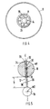
- the closure device 7 comprises a housing 8, on which an access 9, an outlet 10 and an outlet opening 11 are provided (FIG. 2).
- the outlet opening 11 is in the connection area of two superimposed ones Chambers 12, 13 of the housing 8 arranged and extends approximately in a central region between the access 9 and the outlet 10.
- the housing 8 which is preferably made of plastic, is made up of several parts and, according to FIG. 2, is composed of a central part 14, an upper part 15 and a lower part 16.
- the individual parts of the housing 8 are connected to one another, for example, by friction welding.
- a closing device 17 which consists of a mass part 18, a closing part 19 and a connecting member 20, the mass part 18 running at a distance D from the closing part 19 (FIG. 5).
- the rod-shaped connecting member 20 is fixedly connected at its end to the mass part 18 and at its other end to the closing part 19.
- the connecting member 20 penetrates the outlet opening 11 and projects in sections into both chambers 12, 13.
- the diameter of the connecting member 20 is substantially smaller than the diameter of the outlet opening 11.
- the mass part 18 is arranged to a certain extent freely in the chamber 12 facing the outlet 10 and the closing part 19 in the chamber below.
- the chamber 12 receiving the mass part 18 has a substantially larger diameter and a larger volume than the chamber 13. Adjacent to the outlet opening 11, the chamber 12 has a dome-shaped region 35, whereas the section of the chamber 12 facing the outlet 10 is approximately cylindrical is.
- a plurality of guide ribs 21 arranged in a star shape are arranged, on which the mass part 18 rests.
- An upper boundary edge 22 of the guide ribs 21 is connected to the outer housing wall and extends at an angle to a vertical plane A-A, the angle preferably being 45 °.
- the end region 23 of the guide ribs 21 facing the vertical plane AA runs approximately parallel to the latter and, viewed in plan view, on a circular arc which has a larger diameter than the outlet opening 11.
- the chamber 13 receiving the closing part 19 is approximately cylindrical, the inside diameter of this chamber is substantially smaller than the inside diameter of the chamber 12.
- ribs 24 arranged in a star shape are provided for guiding the closing part 19.
- the ribs 24 projecting inwards from the housing wall widen conically from bottom to top, whereby the space for the closing part 19 tapers conically towards the outlet opening 11.
- a partition 25 containing the outlet opening 11, which is dome-shaped on the side facing the mass part 18.
- the partition wall 25 is composed of two sections 26, 27 which are arranged at an angle to one another, the section 26 adjoining the outlet opening 11 forming a conical sealing surface 28 which is located in front of the outlet opening 11.
- both the mass part 19 and the closing part 19 are spherical. However, there is also the possibility of making the mass part 18 and possibly also the closing part 19 conical or the like.
- the mass member 18 is made of a material with a relatively high specific weight, e.g. made of stainless steel, whereas the closing part 19 is made of a lightweight material such as plastic.
- the diameter of the mass part 18 is two to five times, preferably about four times as large as the diameter of the closing part 19.
- the connecting member 20 is formed in one piece with the closing part 19 and receives the mass part 18 at its free end 29.
- a through hole 30 is provided on the mass part 18, through which the connecting member 20 is guided.
- the mass part 18 lies at the bottom on a collar 31 of the connecting member 20 and at the top has a cross-sectional widening 32 (crimping of the connecting member 20) which interacts in a form-fitting manner with a conical chamfer 34 of the mass part 18.
- a central axis 36 of the connecting member 20 runs on an auxiliary plane C-C, which connects the center points M1, M2 of the mass part 18 and the closing part 19.
- the mass part 18 rests on the guide ribs 21 of the overhead chamber 12 and the fuel vapors pass through the chamber 13 and the outlet opening 11 into the flow channels 33 which extend between the guide ribs 21. After passing through the flow channels 33, the fuel vapors flow laterally past the mass part 18 upwards to the outlet 10 of the housing 8. Since the mass part 18 is relatively heavy, the closing part 19 cannot, even under extreme conditions (high outside temperature, altitude), as a result of increased gasification of the fuel are pressed upwards against the sealing surface 28 of the outlet opening 11. In the inclined position S1 or S2 or head position K of the vehicle, however, the closing part 19 is pulled by the weight of the mass part 18 against the outlet opening 11 and closes it effectively, so that no fuel can escape into the open or the activated carbon filter 6.
Landscapes
- Engineering & Computer Science (AREA)
- Chemical & Material Sciences (AREA)
- Combustion & Propulsion (AREA)
- Mechanical Engineering (AREA)
- Life Sciences & Earth Sciences (AREA)
- Sustainable Development (AREA)
- Sustainable Energy (AREA)
- Transportation (AREA)
- General Engineering & Computer Science (AREA)
- Cooling, Air Intake And Gas Exhaust, And Fuel Tank Arrangements In Propulsion Units (AREA)
- Safety Valves (AREA)
Claims (12)
Applications Claiming Priority (2)
| Application Number | Priority Date | Filing Date | Title |
|---|---|---|---|
| DE3709925 | 1987-03-26 | ||
| DE19873709925 DE3709925C1 (de) | 1987-03-26 | 1987-03-26 | Verschlussvorrichtung fuer eine Lueftungsleitung eines Kraftstoffbehaelters |
Publications (3)
| Publication Number | Publication Date |
|---|---|
| EP0283576A2 EP0283576A2 (fr) | 1988-09-28 |
| EP0283576A3 EP0283576A3 (en) | 1989-01-04 |
| EP0283576B1 true EP0283576B1 (fr) | 1991-02-06 |
Family
ID=6324010
Family Applications (1)
| Application Number | Title | Priority Date | Filing Date |
|---|---|---|---|
| EP19870118475 Expired - Lifetime EP0283576B1 (fr) | 1987-03-26 | 1987-12-14 | Dispositif de fermeture d'une conduite d'aération d'un réservoir de carburant |
Country Status (5)
| Country | Link |
|---|---|
| US (1) | US4846208A (fr) |
| EP (1) | EP0283576B1 (fr) |
| JP (1) | JPS63259278A (fr) |
| DE (2) | DE3709925C1 (fr) |
| ES (1) | ES2021003B3 (fr) |
Cited By (1)
| Publication number | Priority date | Publication date | Assignee | Title |
|---|---|---|---|---|
| DE102009010406A1 (de) * | 2009-02-26 | 2010-09-02 | Magna Steyr Fuel Systems Gesmbh | Einfüllkopf für einen Kraftstoffbehälter mit einer Schutzvorrichtung |
Families Citing this family (7)
| Publication number | Priority date | Publication date | Assignee | Title |
|---|---|---|---|---|
| US5042519A (en) * | 1990-04-03 | 1991-08-27 | Club Car, Inc. | Fuel tank vent |
| EP0648637A1 (fr) * | 1993-09-15 | 1995-04-19 | General Motors Corporation | Dispositif de recyclage de vapeurs |
| US5762093A (en) * | 1995-03-29 | 1998-06-09 | Attwood Corporation | Fuel overflow restrictor/water intake restraining devices |
| US5782258A (en) * | 1995-12-11 | 1998-07-21 | Alfmeier Corporation | Vapor recovery fuel tank system |
| DE10002613A1 (de) | 2000-01-22 | 2001-07-26 | Volkswagen Ag | Kraftstoffversorgung für eine Kraftfahrzeug-Brennkraftmaschine |
| US6886579B2 (en) * | 2003-03-03 | 2005-05-03 | Swift Enterprises, Ltd. | Vent cap |
| EP1564057B1 (fr) * | 2004-02-10 | 2008-03-26 | Effbe-France S.A.S. | Agencement de vannes comprenant une pluralité de vannes liées en série pour empêcher une fuite de carburant d'un réservoir de véhicule indépendamment de l'orientation du véhicule |
Family Cites Families (7)
| Publication number | Priority date | Publication date | Assignee | Title |
|---|---|---|---|---|
| FR544427A (fr) * | 1921-12-10 | 1922-09-22 | Dispositif obturateur automatique pour canalisations | |
| US2065783A (en) * | 1935-05-03 | 1936-12-29 | Electric Storage Battery Co | Nonspill vent plug |
| US2355288A (en) * | 1942-04-24 | 1944-08-08 | Edison Inc Thomas A | Nonspill vent means |
| DE1004877B (de) * | 1956-10-17 | 1957-03-21 | Gutehoffnungshuette Sterkrade | Entlueftungsventil fuer kippbare Fluessigkeitsbehaelter, vorzugsweise von hydraulischen Grubenstempeln |
| DE2503731C3 (de) * | 1975-01-30 | 1981-05-07 | Dr.Ing.H.C. F. Porsche Ag, 7000 Stuttgart | Verschlußvorrichtung für eine Lüftungsleitung eines Kraftstoffbehälters |
| US3994360A (en) * | 1975-06-06 | 1976-11-30 | Colt Industries Operating Corporation | Safety shut-off fuel system |
| JPS56141473A (en) * | 1980-04-07 | 1981-11-05 | Nissan Motor Co Ltd | Pressure controller equipped with liquid effluence preventing mechanism |
-
1987
- 1987-03-26 DE DE19873709925 patent/DE3709925C1/de not_active Expired
- 1987-12-14 DE DE8787118475T patent/DE3768002D1/de not_active Expired - Lifetime
- 1987-12-14 ES ES87118475T patent/ES2021003B3/es not_active Expired - Lifetime
- 1987-12-14 EP EP19870118475 patent/EP0283576B1/fr not_active Expired - Lifetime
-
1988
- 1988-03-25 JP JP63069907A patent/JPS63259278A/ja active Pending
- 1988-03-28 US US07/174,221 patent/US4846208A/en not_active Expired - Fee Related
Cited By (2)
| Publication number | Priority date | Publication date | Assignee | Title |
|---|---|---|---|---|
| DE102009010406A1 (de) * | 2009-02-26 | 2010-09-02 | Magna Steyr Fuel Systems Gesmbh | Einfüllkopf für einen Kraftstoffbehälter mit einer Schutzvorrichtung |
| DE102009010406B4 (de) * | 2009-02-26 | 2011-09-22 | Magna Steyr Fuel Systems Gesmbh | Einfüllkopf für einen Kraftstoffbehälter mit einer Schutzvorrichtung |
Also Published As
| Publication number | Publication date |
|---|---|
| JPS63259278A (ja) | 1988-10-26 |
| US4846208A (en) | 1989-07-11 |
| ES2021003B3 (es) | 1991-10-16 |
| DE3768002D1 (de) | 1991-03-14 |
| EP0283576A2 (fr) | 1988-09-28 |
| EP0283576A3 (en) | 1989-01-04 |
| DE3709925C1 (de) | 1988-05-19 |
Similar Documents
| Publication | Publication Date | Title |
|---|---|---|
| EP0223931B1 (fr) | Pipe de remplissage de réservoirs de carburant, notamment pour véhicules automobiles | |
| DE2922876C2 (de) | Einfüllstutzen für einen Kraftfahrzeug-Kraftstoffbehälter | |
| DE19510821C2 (de) | Kraftstoffbehälter für Fahrzeuge, insbesondere Kraftfahrzeuge | |
| DE3442626A1 (de) | Fluidabscheider, insbesondere gas/fluessigkeit-abscheider | |
| DE3108591A1 (de) | Vorichtung zur zusetzung von kohlensaeure zu getraenken | |
| EP0283576B1 (fr) | Dispositif de fermeture d'une conduite d'aération d'un réservoir de carburant | |
| DE3016596C2 (fr) | ||
| CH643982A5 (de) | Vorrichtung und verfahren zum vereinzeln und ablegen von koernigem gut, insbesondere saatgut. | |
| DE2045458A1 (de) | Entlüftungsvorrichtung fur Kraft stoffbehalter | |
| DE2503731B2 (de) | Verschlußvorrichtung für eine Lüftungsleitung eines Kraftstoffbehälters | |
| EP3458177B1 (fr) | Filtre de vapeurs de carburant pour un dispositif d'aération de réservoir d'un véhicule automobile présentant des caractéristiques de chargement améliorées | |
| DE4242599A1 (de) | Behälterverschluß | |
| DE19523417C1 (de) | Verfahren zur Entstaubung eines Rohgasstromes und/oder Sorption von gasförmigen Stoffen aus dem Rohgasstrom und Vorrichtung zur Durchführung des Verfahrens | |
| DE3146537C1 (de) | Aktivkohlefilter fuer Dunstabzugshauben | |
| DE3332415C2 (fr) | ||
| DE1218892B (de) | Kugelgelenk-Beluefter fuer den Innenraum von Fahrzeugen | |
| DE2056087B2 (fr) | ||
| EP1437563B1 (fr) | Accumulateur pour un appareil de climatisation, en particulier pour un appareil de climatisation de véhicule | |
| DE2034753C3 (de) | Faltenbalg | |
| DE3318797C2 (de) | Zellenradschleuse | |
| DE2904121C2 (fr) | ||
| DE2510576B2 (de) | Verfahren zur Reinigung von Schmutzgas und Reinigungsvorrichtung zur Durchführung des Verfahrens | |
| DE2610732C3 (de) | Hohlträger eines Personenkraftwagens | |
| DE3015189C2 (de) | Entlüftungseinrichtung für Kraftstofftanks von Fahrzeugen | |
| DE2163735B2 (de) | Vorrichtung zum abscheiden von fluessigkeitstropfen aus einem stroemenden gasfoermigen medium |
Legal Events
| Date | Code | Title | Description |
|---|---|---|---|
| PUAI | Public reference made under article 153(3) epc to a published international application that has entered the european phase |
Free format text: ORIGINAL CODE: 0009012 |
|
| AK | Designated contracting states |
Kind code of ref document: A2 Designated state(s): DE ES FR GB IT SE |
|
| PUAL | Search report despatched |
Free format text: ORIGINAL CODE: 0009013 |
|
| AK | Designated contracting states |
Kind code of ref document: A3 Designated state(s): DE ES FR GB IT SE |
|
| 17P | Request for examination filed |
Effective date: 19890125 |
|
| 17Q | First examination report despatched |
Effective date: 19900320 |
|
| ITF | It: translation for a ep patent filed | ||
| GRAA | (expected) grant |
Free format text: ORIGINAL CODE: 0009210 |
|
| AK | Designated contracting states |
Kind code of ref document: B1 Designated state(s): DE ES FR GB IT SE |
|
| REF | Corresponds to: |
Ref document number: 3768002 Country of ref document: DE Date of ref document: 19910314 |
|
| GBT | Gb: translation of ep patent filed (gb section 77(6)(a)/1977) | ||
| ET | Fr: translation filed | ||
| PLBE | No opposition filed within time limit |
Free format text: ORIGINAL CODE: 0009261 |
|
| STAA | Information on the status of an ep patent application or granted ep patent |
Free format text: STATUS: NO OPPOSITION FILED WITHIN TIME LIMIT |
|
| 26N | No opposition filed | ||
| PGFP | Annual fee paid to national office [announced via postgrant information from national office to epo] |
Ref country code: SE Payment date: 19921207 Year of fee payment: 6 |
|
| PGFP | Annual fee paid to national office [announced via postgrant information from national office to epo] |
Ref country code: ES Payment date: 19921215 Year of fee payment: 6 |
|
| PG25 | Lapsed in a contracting state [announced via postgrant information from national office to epo] |
Ref country code: SE Effective date: 19931215 |
|
| PG25 | Lapsed in a contracting state [announced via postgrant information from national office to epo] |
Ref country code: ES Free format text: LAPSE BECAUSE OF NON-PAYMENT OF DUE FEES Effective date: 19941215 |
|
| PGFP | Annual fee paid to national office [announced via postgrant information from national office to epo] |
Ref country code: FR Payment date: 19941228 Year of fee payment: 8 |
|
| EUG | Se: european patent has lapsed |
Ref document number: 87118475.0 Effective date: 19940710 |
|
| PGFP | Annual fee paid to national office [announced via postgrant information from national office to epo] |
Ref country code: GB Payment date: 19951207 Year of fee payment: 9 |
|
| PG25 | Lapsed in a contracting state [announced via postgrant information from national office to epo] |
Ref country code: FR Effective date: 19960830 |
|
| REG | Reference to a national code |
Ref country code: FR Ref legal event code: ST |
|
| PG25 | Lapsed in a contracting state [announced via postgrant information from national office to epo] |
Ref country code: GB Effective date: 19961214 |
|
| GBPC | Gb: european patent ceased through non-payment of renewal fee |
Effective date: 19961214 |
|
| PGFP | Annual fee paid to national office [announced via postgrant information from national office to epo] |
Ref country code: DE Payment date: 19971217 Year of fee payment: 11 |
|
| PG25 | Lapsed in a contracting state [announced via postgrant information from national office to epo] |
Ref country code: DE Free format text: LAPSE BECAUSE OF NON-PAYMENT OF DUE FEES Effective date: 19991001 |
|
| REG | Reference to a national code |
Ref country code: ES Ref legal event code: FD2A Effective date: 19950112 |
|
| PG25 | Lapsed in a contracting state [announced via postgrant information from national office to epo] |
Ref country code: IT Free format text: LAPSE BECAUSE OF NON-PAYMENT OF DUE FEES;WARNING: LAPSES OF ITALIAN PATENTS WITH EFFECTIVE DATE BEFORE 2007 MAY HAVE OCCURRED AT ANY TIME BEFORE 2007. THE CORRECT EFFECTIVE DATE MAY BE DIFFERENT FROM THE ONE RECORDED. Effective date: 20051214 |