EP0283996A2 - Schreibmarkerschnittstelle für Wellenformanzeiger - Google Patents
Schreibmarkerschnittstelle für Wellenformanzeiger Download PDFInfo
- Publication number
- EP0283996A2 EP0283996A2 EP88104487A EP88104487A EP0283996A2 EP 0283996 A2 EP0283996 A2 EP 0283996A2 EP 88104487 A EP88104487 A EP 88104487A EP 88104487 A EP88104487 A EP 88104487A EP 0283996 A2 EP0283996 A2 EP 0283996A2
- Authority
- EP
- European Patent Office
- Prior art keywords
- waveform
- cursor
- cursors
- display
- interface
- Prior art date
- Legal status (The legal status is an assumption and is not a legal conclusion. Google has not performed a legal analysis and makes no representation as to the accuracy of the status listed.)
- Granted
Links
Images


Classifications
-
- G—PHYSICS
- G01—MEASURING; TESTING
- G01R—MEASURING ELECTRIC VARIABLES; MEASURING MAGNETIC VARIABLES
- G01R13/00—Arrangements for displaying electric variables or waveforms
- G01R13/20—Cathode-ray oscilloscopes
- G01R13/22—Circuits therefor
- G01R13/30—Circuits for inserting reference markers, e.g. for timing, for calibrating, for frequency marking
Definitions
- the present invention relates to waveform display instruments, and more particularly to a cursor interface for waveform displays which allows an operator to adjust the relative positions of a displayed waveform and measurement cursors in a fast, intuitive manner.
- each cursor has its own control knob and the waveform display has a gain and position adjustment.
- the gain and position of the waveform have to be adjusted so that both points on the waveform are displayed.
- the cursors are separately adjusted to overlie the respective points and the resulting measurement is read from the graticule scale on the display.
- this technique provides fairly accurate results.
- the measurement accuracy is considerably less.
- the present invention provides a cursor interface for waveform displays which provides a means for locking respective cursors to the waveform so that both points between which a measurement is made need not appear on the display simultaneously.
- the position and gain of a waveform are adjusted relative to a first cursor to allow accurate placement of the first cursor over a first point of the waveform.
- the cursor is then locked to the waveform so that movement of the waveform results in corresponding movement of the cursor.
- the position and gain of the waveform are then adjusted relative to a second cursor to allow accurate placement of the second cursor over a second point of the waveform.
- the measurement value between the two cursors is automatically calculated and displayed as a time differential and corresponding frequency regardless of whether both or either cursor appears on the display.
- an instrument 10 having a video input signal, such as a television video signal.
- the video signal is conventionally processed in the analog domain by an analog processor 12, digitized by a digitizer 14, and stored in an acquisition memory 16.
- the acquisition memory 16 is connected to a communications bus 18 to which also are connected a central processing unit (CPU) 20 with associated ROM 22 and RAM 24, and a display interface unit 26.
- the display interface unit 26 includes the RAM 24, a display memory 28 and an interface circuit 30. The contents of the display memory 28 are displayed on a screen 32.
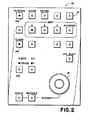
- the digitized video data from the acquisition memory 16 is processed by the CPU 20 according to the functions and parameters input by an operator via function buttons 34 and a rotary encoder 36 on a front panel, and via interaction with the screen 32.
- the processed data is stored in the display memory 28 together with appropriate scales, cursors and display information. Movement and gain of a waveform on the screen 32 are controlled by an EXPAND/MOVE function button 34a and the rotary encoder 36.
- the waveform display is selected by the WAVEFORM function button 34b.
- the cursor interface function is selected by activating a CURSOR function button 34c on the front panel 38.
- a plurality of soft keys 40 may be used in lieu of function buttons 34 to display functions on the screen 32 together with a waveform 42.
- the soft keys 40 for the cursor interface include a CENTER LEFT key 40a, a LOCK LEFT key 40b, a CENTER RIGHT key 40c, a LOCK RIGHT key 40d and a RESET CURSORS key 40e. Initially, or in response to the RESET CURSORS key 40e, both cursors 46 are unlocked from the waveform 42 and then centered, or preset to a predetermined position, within a display area 44 of the screen 32.
- the cursors 46 may be centered individually by contacting the respective CENTER LEFT and CENTER RIGHT keys 40a, 40c. Movement or gain changes to the waveform may be made according to the status of the EXPAND/MOVE button 34a by rotating the rotary encoder 36 in the appropriate direction. Activation of the LOCK LEFT or LOCK RIGHT keys 40b, 40d serves to transform the coordinates of the respective cursors via the CPU 20 from those of the display area 44 in terms of pixel positions to those of the waveform 42 in terms of data sample numbers so that the cursor is associated with the underlying point on the waveform.
- Subsequent movement of the waveform 42 results in corresponding movement of the locked cursor 46, and subsequent centering of the cursor by the respective cursor center keys 40a, 40c while locked to the waveform results in corresponding movement of the waveform.
- a second activation of the lock keys 40b, 40d serves to unlock the respective cursor 46 from the waveform 42.
- the difference between the two cursors 46 is determined by the CPU 20 and indicated in an information area 48, which is shown between the display area 44 and the soft keys 40.
- an operator desires to measure the width of a horizontal sync pulse from a television video signal, for example, the operator would expand the waveform 42 via the rotary encoder 36 while the EXPAND/MOVE button 34a is in the expand mode. Then in the move mode the operator would move a point on one edge of the sync pulse under one of the cursors 46 with considerable accuracy. Activation of the appropriate cursor lock key 40b or 40d would lock the selected cursor 46 to the waveform 42. The operator then moves the waveform 42 so that the opposite edge of the sync pulse is under the other cursor 46. The resulting difference in time is displayed in the information area 48 as a Time Interval A-B and as a Frequency. As shown in Fig.
- the right cursor is locked to the waveform 42 at the trailing edge of horizontal sync and has been moved off the screen 32 due to the expansion of the waveform.
- the left cursor 46 is located at the leading edge of sync, indicated by the fact that in the information area 48 the 50% point is indicated.
- the time difference is 4.7074 microseconds corresponding to a frequency of 212.4316 kHz. Although the frequency readout is not particularly significant in this instance, if the time difference was between consecutive horizontal sync leading edges, the frequency would have much greater significance.
- the present invention provides a cursor interface on a waveform display which allows accurate cursor placement and waveform measurements without requiring that both cursors be on the screen simultaneously by locking one or both cursors to the waveform and displaying the resulting time difference between the cursors and the corresponding frequency.
Landscapes
- Physics & Mathematics (AREA)
- General Physics & Mathematics (AREA)
- Controls And Circuits For Display Device (AREA)
- Digital Computer Display Output (AREA)
- Position Input By Displaying (AREA)
Applications Claiming Priority (2)
| Application Number | Priority Date | Filing Date | Title |
|---|---|---|---|
| US30757 | 1987-03-24 | ||
| US07/030,757 US4751504A (en) | 1987-03-24 | 1987-03-24 | Cursor interface for waveform displays |
Publications (3)
| Publication Number | Publication Date |
|---|---|
| EP0283996A2 true EP0283996A2 (de) | 1988-09-28 |
| EP0283996A3 EP0283996A3 (de) | 1991-06-12 |
| EP0283996B1 EP0283996B1 (de) | 1995-12-20 |
Family
ID=21855861
Family Applications (1)
| Application Number | Title | Priority Date | Filing Date |
|---|---|---|---|
| EP88104487A Expired - Lifetime EP0283996B1 (de) | 1987-03-24 | 1988-03-21 | Schreibmarkerschnittstelle für Wellenformanzeiger |
Country Status (6)
| Country | Link |
|---|---|
| US (1) | US4751504A (de) |
| EP (1) | EP0283996B1 (de) |
| JP (1) | JPH07104364B2 (de) |
| CA (1) | CA1303262C (de) |
| DE (1) | DE3854794T2 (de) |
| DK (1) | DK157788A (de) |
Cited By (3)
| Publication number | Priority date | Publication date | Assignee | Title |
|---|---|---|---|---|
| GB2312583A (en) * | 1996-04-25 | 1997-10-29 | Tektronix Inc | Digital cursors for serial digital television waveform monitoring |
| WO1998048286A3 (de) * | 1997-04-23 | 1999-01-28 | Siemens Ag | Datenverarbeitungsanlage und verfahren zur visualisierung eines gradienten in einem auf einem bildschirm dargestellten diagramm |
| JP2025027352A (ja) * | 2023-08-14 | 2025-02-27 | 横河電機株式会社 | 波形測定器、波形測定器の制御方法、及び、プログラム |
Families Citing this family (13)
| Publication number | Priority date | Publication date | Assignee | Title |
|---|---|---|---|---|
| US5339094A (en) * | 1987-08-11 | 1994-08-16 | Murrell Nicholas J | VDU line marker |
| US4996654A (en) * | 1988-12-22 | 1991-02-26 | Tektronix, Inc. | Method of displaying acquired data |
| JP2736149B2 (ja) * | 1990-03-23 | 1998-04-02 | 株式会社東芝 | トレンドグラフ変倍装置 |
| US5463731A (en) * | 1990-06-27 | 1995-10-31 | Telefonaktiebolaget L M Ericsson | Monitor screen graphic value indicator system |
| US5004975A (en) * | 1990-06-28 | 1991-04-02 | Tektronix, Inc. | Adjustable electronic graticules for measuring waveform distortions |
| JP2981769B2 (ja) * | 1990-11-28 | 1999-11-22 | セイコーインスツルメンツ株式会社 | 波形表示装置 |
| KR940007665A (ko) * | 1992-09-02 | 1994-04-27 | 윤종용 | 묘화(猫畵)의 특정부위 이동제어방법 |
| JP3153684B2 (ja) * | 1993-09-14 | 2001-04-09 | リーダー電子株式会社 | 信号波形表示装置及び表示方法 |
| US5631667A (en) * | 1993-12-08 | 1997-05-20 | Cadwell Industries, Inc. | Frequency and amplitude measurement tool for electronic displays |
| US5898307A (en) * | 1996-04-10 | 1999-04-27 | Snap-On Technologies, Inc. | Independent cursor control in dual-trace engine analyzer scope |
| US6232952B1 (en) * | 1998-09-30 | 2001-05-15 | Genesis Microchip Corp. | Method and apparatus for comparing frequently the phase of a target clock signal with the phase of a reference clock signal enabling quick synchronization |
| FR2854254B1 (fr) * | 2003-04-22 | 2005-06-17 | Schneider Electric Ind Sas | Terminal d'exploitation, notamment pour automatismes |
| JP5574192B2 (ja) * | 2012-08-08 | 2014-08-20 | 横河電機株式会社 | 波形表示装置 |
Family Cites Families (8)
| Publication number | Priority date | Publication date | Assignee | Title |
|---|---|---|---|---|
| JPS51113762A (en) * | 1975-03-31 | 1976-10-07 | Ricoh Co Ltd | Time indication method in wave-memory |
| US4053831A (en) * | 1975-03-30 | 1977-10-11 | Ricoh Co., Ltd. | Waveform analysis system |
| US4476432A (en) * | 1982-02-10 | 1984-10-09 | Tektronix, Inc. | Waveform measurement system |
| JPS5995472A (ja) * | 1982-11-25 | 1984-06-01 | Sony Tektronix Corp | 波形表示装置 |
| US4628254A (en) * | 1984-01-16 | 1986-12-09 | Tektronix, Inc. | Method for digitally measuring waveforms |
| US4686523A (en) * | 1984-01-31 | 1987-08-11 | Tektronix, Inc. | Cursor display for oscilloscopes |
| JPH0794990B2 (ja) * | 1985-05-31 | 1995-10-11 | 横河・ヒユ−レツト・パツカ−ド株式会社 | 表示装置 |
| JPS61288164A (ja) * | 1985-06-17 | 1986-12-18 | Advantest Corp | 波形表示装置 |
-
1987
- 1987-03-24 US US07/030,757 patent/US4751504A/en not_active Expired - Lifetime
-
1988
- 1988-02-29 CA CA000560100A patent/CA1303262C/en not_active Expired - Lifetime
- 1988-03-21 DE DE3854794T patent/DE3854794T2/de not_active Expired - Lifetime
- 1988-03-21 EP EP88104487A patent/EP0283996B1/de not_active Expired - Lifetime
- 1988-03-23 DK DK157788A patent/DK157788A/da not_active IP Right Cessation
- 1988-03-24 JP JP63070851A patent/JPH07104364B2/ja not_active Expired - Lifetime
Cited By (4)
| Publication number | Priority date | Publication date | Assignee | Title |
|---|---|---|---|---|
| GB2312583A (en) * | 1996-04-25 | 1997-10-29 | Tektronix Inc | Digital cursors for serial digital television waveform monitoring |
| GB2312583B (en) * | 1996-04-25 | 2000-04-19 | Tektronix Inc | Digital cursors for serial digital television waveform monitors |
| WO1998048286A3 (de) * | 1997-04-23 | 1999-01-28 | Siemens Ag | Datenverarbeitungsanlage und verfahren zur visualisierung eines gradienten in einem auf einem bildschirm dargestellten diagramm |
| JP2025027352A (ja) * | 2023-08-14 | 2025-02-27 | 横河電機株式会社 | 波形測定器、波形測定器の制御方法、及び、プログラム |
Also Published As
| Publication number | Publication date |
|---|---|
| JPH07104364B2 (ja) | 1995-11-13 |
| EP0283996A3 (de) | 1991-06-12 |
| DE3854794D1 (de) | 1996-02-01 |
| DK157788D0 (da) | 1988-03-23 |
| CA1303262C (en) | 1992-06-09 |
| US4751504A (en) | 1988-06-14 |
| DK157788A (da) | 1988-09-25 |
| JPS63253261A (ja) | 1988-10-20 |
| DE3854794T2 (de) | 1996-08-08 |
| EP0283996B1 (de) | 1995-12-20 |
Similar Documents
| Publication | Publication Date | Title |
|---|---|---|
| US4751504A (en) | Cursor interface for waveform displays | |
| EP0283995B1 (de) | Berührungsgesteuertes Zoom für Wellenformanzeigen | |
| EP0653696B1 (de) | Berührungssteuerung der Zeigerstelle | |
| US7443385B2 (en) | Data processing | |
| EP0916308B1 (de) | Ultraschall-Diagnosegerät, Verfahren zur Cursor-Darstellung, und Messgerät | |
| JPS62209368A (ja) | 測定器制御装置 | |
| JPH0236364A (ja) | マーカ表示方法及び装置 | |
| US4761640A (en) | Positioning cursors at specific points on a waveform display | |
| US4134149A (en) | High sweep rate waveform display control for digital recording waveform devices | |
| US6583801B2 (en) | Data processing apparatus utilizing proximity sensing to determine whether user's hand is within predetermined distance | |
| US4740841A (en) | Correlation of video data between two display formats | |
| US4764721A (en) | Locking scales to waveform displays | |
| US4816897A (en) | Chrominance to luminance delay and gain measurement display | |
| JPH0353648B2 (de) | ||
| EP0829800B1 (de) | Koordinateneingabevorrichtung | |
| JP3033465B2 (ja) | パラメータ設定装置 | |
| JPH0359418A (ja) | 計測器の表示部への設定内容表示方法 | |
| JPH0794990B2 (ja) | 表示装置 | |
| JPH05108263A (ja) | マウス入力装置 | |
| JPH06105845A (ja) | 超音波診断装置 | |
| JPH0630831U (ja) | デジタルオシロスコープ | |
| JP3128792B2 (ja) | 数値入力装置 | |
| JPH06289835A (ja) | カーソル表示装置 | |
| JPS63191193A (ja) | マルチウインドウ表示装置のカ−ソル制御方式 | |
| JPH0611363A (ja) | 表示装置のデータ読み取り方式 |
Legal Events
| Date | Code | Title | Description |
|---|---|---|---|
| PUAI | Public reference made under article 153(3) epc to a published international application that has entered the european phase |
Free format text: ORIGINAL CODE: 0009012 |
|
| AK | Designated contracting states |
Kind code of ref document: A2 Designated state(s): DE FR GB NL |
|
| PUAL | Search report despatched |
Free format text: ORIGINAL CODE: 0009013 |
|
| AK | Designated contracting states |
Kind code of ref document: A3 Designated state(s): DE FR GB NL |
|
| RHK1 | Main classification (correction) |
Ipc: G01R 13/30 |
|
| 17P | Request for examination filed |
Effective date: 19910805 |
|
| 17Q | First examination report despatched |
Effective date: 19921217 |
|
| GRAA | (expected) grant |
Free format text: ORIGINAL CODE: 0009210 |
|
| AK | Designated contracting states |
Kind code of ref document: B1 Designated state(s): DE FR GB NL |
|
| PG25 | Lapsed in a contracting state [announced via postgrant information from national office to epo] |
Ref country code: NL Free format text: LAPSE BECAUSE OF FAILURE TO SUBMIT A TRANSLATION OF THE DESCRIPTION OR TO PAY THE FEE WITHIN THE PRESCRIBED TIME-LIMIT Effective date: 19951220 Ref country code: FR Effective date: 19951220 |
|
| REF | Corresponds to: |
Ref document number: 3854794 Country of ref document: DE Date of ref document: 19960201 |
|
| EN | Fr: translation not filed | ||
| NLV1 | Nl: lapsed or annulled due to failure to fulfill the requirements of art. 29p and 29m of the patents act | ||
| PLBE | No opposition filed within time limit |
Free format text: ORIGINAL CODE: 0009261 |
|
| STAA | Information on the status of an ep patent application or granted ep patent |
Free format text: STATUS: NO OPPOSITION FILED WITHIN TIME LIMIT |
|
| 26N | No opposition filed | ||
| REG | Reference to a national code |
Ref country code: GB Ref legal event code: IF02 |
|
| PGFP | Annual fee paid to national office [announced via postgrant information from national office to epo] |
Ref country code: GB Payment date: 20070214 Year of fee payment: 20 |
|
| PGFP | Annual fee paid to national office [announced via postgrant information from national office to epo] |
Ref country code: DE Payment date: 20070226 Year of fee payment: 20 |
|
| REG | Reference to a national code |
Ref country code: GB Ref legal event code: PE20 Expiry date: 20080320 |
|
| PG25 | Lapsed in a contracting state [announced via postgrant information from national office to epo] |
Ref country code: GB Free format text: LAPSE BECAUSE OF EXPIRATION OF PROTECTION Effective date: 20080320 |