EP0284089A2 - Multiplexvorrichtung mit BSI-Codeverarbeitungs- und Bitverschachtelungsfunktionen - Google Patents
Multiplexvorrichtung mit BSI-Codeverarbeitungs- und Bitverschachtelungsfunktionen Download PDFInfo
- Publication number
- EP0284089A2 EP0284089A2 EP88104844A EP88104844A EP0284089A2 EP 0284089 A2 EP0284089 A2 EP 0284089A2 EP 88104844 A EP88104844 A EP 88104844A EP 88104844 A EP88104844 A EP 88104844A EP 0284089 A2 EP0284089 A2 EP 0284089A2
- Authority
- EP
- European Patent Office
- Prior art keywords
- bsi
- multiplexing
- bit
- code
- pcm
- Prior art date
- Legal status (The legal status is an assumption and is not a legal conclusion. Google has not performed a legal analysis and makes no representation as to the accuracy of the status listed.)
- Granted
Links
Images


Classifications
-
- H—ELECTRICITY
- H04—ELECTRIC COMMUNICATION TECHNIQUE
- H04J—MULTIPLEX COMMUNICATION
- H04J3/00—Time-division multiplex systems
- H04J3/02—Details
- H04J3/04—Distributors combined with modulators or demodulators
- H04J3/047—Distributors with transistors or integrated circuits
-
- H—ELECTRICITY
- H04—ELECTRIC COMMUNICATION TECHNIQUE
- H04L—TRANSMISSION OF DIGITAL INFORMATION, e.g. TELEGRAPHIC COMMUNICATION
- H04L7/00—Arrangements for synchronising receiver with transmitter
- H04L7/0079—Receiver details
- H04L7/0083—Receiver details taking measures against momentary loss of synchronisation, e.g. inhibiting the synchronisation, using idle words or using redundant clocks
Definitions
- the present invention relates to a multiplexing apparatus having a BSI-code processing function and a bit interleave function.
- a reliable transmission of all kinds of information signals must be guaranteed.
- a Clear Channel Capability is required in which timing clock signals can be stably extracted from the input information signals without generating code errors, even when the input information signals include consecutive "0"s or "1"s, i.e., direct current components.
- the codes on transmission lines must be bit-sequence independent (BSI).
- PCM signals having a basic signal transmission speed are given with frame structures provided with multiplexing control signals such as frame synchronous signals and channel numbers of channels to be multiplexed.
- multiplexing control signals such as frame synchronous signals and channel numbers of channels to be multiplexed.
- the signal speed after the multiplexing is made an integer multiple of the basic PCM signal speed.
- the synchronous multiplexing technique has been devised while taking only the multiplexing system into account, and, therefore, is not satisfactory as a transmission system with the clear channel capability. Namely, no consideration has been given in the synchronous multiplexing system to realizing the BSI of transmission line codes. Therefore, there is a need for a constitution which takes into account the BSI of the transmission system as well as the synchronous multiplexing system.
- the BSI process of digital transmission codes is realized in a transmission terminal equipment, and a time division multiplexing process, etc., is usually carried out in a multiplexing unit.
- a signal speed of the PCM hierarchy is used as an interfacing speed between the time division multiplexing process and the transmission terminal equipment.
- the transmission terminal equipment which receives multiplexed PCM signals must carry out a speed conversion of the PCM signals by executing the BSI process such as an 8B1C (8th-bit one-complement by which one block becomes 9 bits) or a 5B6B (5th-bit 6-bit by which one block becomes 6 bits) and transmit the speed-converted signals to a transmission line.
- the signals are subjected to a reverse BSI process, a speed conversion process and a demodulating process, and transmitted to a multiplex converter.
- the BSI process is executed within the transmission terminal equipment, as later described in more detail with reference to the drawings.
- the multiplexing system and the transmission system are provided separately. Therefore, even if a frame constitution which is adequate for the multiplexing system is adopted, that is, even if information signals with a basic PCM signal speed are provided in advance with a frame constitution to which control signals such as frame synchronous signals and channel numbers of channels to be multiplexed are added for the synchronous multiplexing and demultiplexing processes, the transmission terminal equipment treats these control signals and frame synchronous signals only as information signals.
- the conventional BSI process such as a BSI bit insertion and removal, necessary for the transmission system, is carried out in each transmission terminal equipment.
- the multiplexed signal having a regularized speed of, for example, an integer multiple of the basic PCM signal speed must be converted into a signal with the BSI having an increased speed. Because of the speed conversion, the advantage of the multiplexing system of the digital hierarchy utilizing the basic PCM signal speed is lost in the transmission equipment. Further, due to the necessity of the speed conversion, the hardware scale of the transmission equipment becomes large and expensive.
- An object of the present invention is to provide a multiplexing apparatus having a BSI-code processing function and a bit interleave function in which the advantage of the synchronous multiplex system is maintained.
- Another object of the present invention is to provide the above multiplexing apparatus in which each unit has no speed conversion part.
- Still another object of the present invention is to provide the above multiplexing apparatus in which a small-scale transmission equipment is provided.
- a still further object of the present invention is to provide the above multiplexing apparatus in which the transmission equipment is provided at a low cost.
- the multiplexing apparatus has a BSI-code processing function and a bit interleave function, and comprises: a BSI-code adding means for adding BSI codes to the PCM signals before multiplexing; a BSI-code position shifting means for shifting the positions of the BSI codes in the PCM signals to different positions respectively with respect to the PCM signals of a plurality of channels; and a multiplexing means for multiplexing the outputs of the BSI-code position shifting means by a bit-interleave mode.
- a multiplexing apparatus of a bit interleave type for time-division multiplex on PCM signals of a plurality of channels bit by bit to convert the PCM signals into a high-speed PCM signal having a BSI-code processing function and a bit interleave function, BSI bits being inserted into each predetermined block of input PCM signals in advance, and comprising: basic PCM signal channel processing portion each for shifting positions of said BSI bits of said respective channels and for multiplexing the shifted bits with the PCM signals of corresponding channel.
- the outputs of the basic PCM signal channel processing portions are multiplexed under a bit interleave mode.
- the multiplexed signals are inverted at the BSI bits.
- a multiplexing apparatus of a bit interleave type for time-division multiplex on PCM signals of a plurality of channels bit by bit to convert the PCM signals into a high-speed PCM signal the multiplexing apparatus having a BSI-code processing function and a bit interleave function, and comprising: a BSI-code adding means for adding BSI codes to the PCM signals before multiplexing; a basic PCM signal channel processing means; and a multiplexing portion.
- the basic PCM signal channel processing means includes separating means for separating a frame control signal, a BSI code, and data, included in each frame of the input PCM signals; a memory for temporarily buffering the data; frame control means changing the channel number in the frame control signal; BSI-code shifting means for shifting the BSI code; multiplexing means for multiplexing data read from the memory, the frame control signal, and the BSI code; and a multiplexing portion comprising bit interleave multiplexing means for multiplexing a bit sequence input from the PCM signals of a plurality of channels.
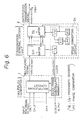
- Figure 6 is a block diagram showing a conventional BSI bit interleave multiplex system.
- 1 represents a multiplex converter
- 2 represents a transmission terminal equipment.
- the multiplex converter 1 multiplexes input signals CHl to CHn of "n" channels to supply a signal of (n ⁇ fo + a) bps to the transmission terminal equipment 2, and further, supplies a clock of (n ⁇ fo + a) Hz corresponding to the signal.
- the "a" bits are those allocated for a frame control signal in each frame.
- the multiplexed signal is subjected to a serial/parallel (S/P) conversion, a buffering, and a parallel/serial (P/S) conversion and output.
- S/P serial/parallel
- P/S parallel/serial
- Figure 7 is a view showing the converting process to the 9 bits.
- the multiplexed signal is divided into segments each having 8 bits. For example, an 8th bit #8 in one block is inverted to #8 and added to the block. The signal is then sent as a multiplexed transmission signal.
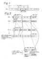
- FIG. 1 is a view showing a data format of a PCM channel which is utilized in a multiplexing apparatus according to the present invention.
- a PCM signal of a channel CHi before multiplexing includes a sequence of frames each consisting of a frame synchronizing signal F, a channel number ID, and an information payload (data) IP.
- a BSI bit is inserted after, for example, each 8-th bit of one block, as shown in Fig. 2.
- FIG. 2 is an explanatory view showing the principle of the present invention.
- information payload IP in each channel is divided into a number of blocks.
- a BSI bit is added to, for example, each block in each of the channels CHl to CHm before multiplexing.
- the BSI bits may be added before input to the multiplexing apparatus. Alternatively, the BSI bits may be added at the input stage of the multiplexing apparatus.
- each BSI bit in a channel CHi is shifted by "i ⁇ k" bits from the originally added position. For example, each BSI bit in the channel CH2 is shifted by "k" bits.
- each BSI bit in the channel CHm is shifted by "m ⁇ k" bits.
- each block including a BSI bit may be entirely shifted by k bits.
- This alternative method causes a delay of the information payload, i.e., data, by k bits, and it is preferable not to delay the information payload.
- the information payload (IP) is not delayed but only the BSI bits are delayed by K bits.
- the positions of the shifted BSI bits are determined by the channel numbers and the predetermined number "k”. The shift of the BSI bits is necessary in order to avoid a continuous series of BSI bits after multiplexing. Since the positions of the BSI bits shifted in each channel can be identified by counting the bit length from the frame control signal in the channel, phases of blocks of the respective channels need not be aligned, although they are aligned in the figure for easy understanding.
- the channels CHl to CHm with the shifted BSI bits are then multiplexed by a bit interleave method.
- a differential 8B1M (8-bit one mark) as illustrated in the figure is used as an example.
- D8B1M differential 8B1M
- a mark M is added to a position corresponding to a 9th bit in each block, and when the mark M is found by a receiver, a bit #8 is inverted to #8 ⁇ , and inserted into the 9th bit.
- a new one block consisting of nine bits #1, ..., #8, and #8 is formed.
- the D.C. components in the PCM signals can be removed by the differential coding.
- 8B1C may be alternatively used as the BSI bit.
- the 9th bit in each block is always an inverted signal of the 8th bit. Therefore, after multiplexing of m channels, an inverted signal appears in at longest m ⁇ k bits so that the BSI is satisfied, although it is not sufficient.
- basic PCM signals are made to have BSI bits when their frames are formed.
- positions of the BSI bits are shifted according to channel numbers of channels to be multiplexed. Therefore, the BSI bit inserting process can be realized without processing high-speed PCM signals after multiplexing.
- the transmission equipment can be simplified and realized in compact sizes while satisfying features of the synchronous multiplex system. Accordingly, clocks in a transmission switching network can be simplified, and multiplexing circuits can be formed in modules so as to reduce the cost.
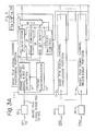
- FIG. 3 is a block diagram showing the constitution of a multiplexing apparatus according to an embodiment of the present invention.
- a reference numeral 10 represents a multiplexing portion corresponding to the conventional multiplex converter 1 shown in Fig. 6.
- Reference numerals 11-1, 11-2, ... 11-m represent basic PCM signal channel processing portions provided to correspond to respective channels for carrying out a preparatory process corresponding to the multiplexing process shown in Fig. 1.
- a numeral 12 represents a frame control signal and BSI bit separating portion which separates information signals (IP), frame control signals and BSI bits one from another.
- a numeral 13 represents a frame synchronization portion for effecting frame synchronization of input signals and generating timing signals necessary for respective circuits.
- a numeral 14 represents an elastic store for adjusting a time for writing or reading information signals.
- a numeral 15 is a frame controlling portion for updating multiplexing overheads of, for example, channel numbers of channels to be multiplexed included in the frame control signals.
- a numeral 16 is a BSI bit shifting portion for shifting positions of BSI bits so as to satisfy the condition that each block in each channel includes at least one BSI bit after multiplexing.
- a numeral 17 is a multiplexing controlling portion for generating frame signals and providing phase adjusting instructions with respect to multiplexing reference phases, according to instructions from a multiplexing channel controlling circuit 19.
- a numeral 18 is a differential coding portion for differentialcoding ("1": inverting data; "0": holding data of a previous time slot) multiplexed signals from the respective channel processing portions (11-1 to 11-m).
- a numeral 19 is the multiplexing channel controlling circuit for generating reference frames necessary for the multiplexing process and instructing channel numbers of the respective channel processing portions.
- a numeral 20 is a bit interleave multiplexing circuit for performing a bit interleave multiplexing.
- Numerals 22-1, 22-2, ..., and 22-m are BSI-code adding circuits for adding BSI codes to the input basic PCM signals.
- a basic PCM signal of each channel is subject to BSI process in the BSI-code adding circuit 22-1, 22-2, ... or 22-m.
- the basic PCM signal after the BSI process is input to the frame control signal and BSI bit separating portion 12 wherein frame control signals and BSI bits are separated from the PCM signal (information payload) and input to the frame controlling portion 15 and the BSI bit shifting portion 16, respectively.
- Information payloads (data) are input to the elastic store 14.
- the BSI bit shifting portion 16 the BSI bits are shifted in advance so that a transmission signal may have the BSI characteristic.
- the multiplexing controlling portion 17 According to a control signal from the multiplexing channel controlling circuit 19, the multiplexing controlling portion 17 generates frame signals and provided instructions with respect to multiplexing phases. Accordingly, the multiplexing circuit 21 multiplexes the data, frame signals and BSI bits.
- Signals of respective channels multiplexed in this way are input to the bit interleave multiplexing circuit 20 in which the signals are multiplexed for each bit under a bit interleave mode.
- the multiplexed signals are differential-coded in the differential-coding portion 18 and transmitted.
- the BSI-code adding circuits 22-1 to 22-m at the input stage of the multiplexing apparatus as shown in Fig. 3 may be omitted and the BSI bits may be added at a transmitting side (not shown in the figure). In this case, the BSI bits are already included in the input basic PCM signals.
- FIG. 4 shows another embodiment of the present invention.
- the multiplexing apparatus includes BSI-code adding circuits 22-1a, 22-2a, ... and 22-ma, basic signal channel processing portions 11-1a, 11-2a, ..., and 11-ma, and a multiplexing portion 10a.
- the BSI-code adding circuits 22-1a, 22-2a, ... and 22-ma are the same as those of Fig. 3.
- Each of the basic signal channel processing portions 11-1a, 11-2a, ..., and 11-ma includes a shift register (SR) 16a and a selector (SEL) 21a.
- the multiplexing portion 10a includes a bit interleave multiplexing circuit 20a and a multiplexing channel controlling circuit 19a.
- the selectors (SEL) 21a are controlled by the multiplexing channel controlling circuit 19a.
- the basic PCM signal in each channel after the BSI processing by the corresponding BSI-code adding circuit is shifted bit by bit in the shift register 16a.
- the selector (SEL) 21a selects, under the control of the multiplexing controlling circuit 19a, the necessary outputs from the outputs Q1 to Qn of the register 16a.
- a one block of, for example, 9 bits is selected at one time.
- the selected block is determined in accordance with the channel number.
- the entirely shifted PCM signal of one block is obtained and the shifted value is determined in accordance with the channel number.
- the outputs of the selectors 21a in all of the basic PCM signal processing portions 11-1a to 11-ma are multiplexed under the bit interleave made by the bit interleave multiplexing circuit 20a.
- the multiplexed signal is output to the outgoing line.
- the BSI bit not only the BSI bit but also the information payload is shifted. It is not difficult to discriminate the information payload by providing a necessary discriminating circuit, although it is not preferable to shift the information payload.
- the BSI bits are shifted before multiplexing, the effect of the present invention is also obtained.
- Figure 5 is an explanatory view showing an experimental effect of the differential 8B1M used for the BSI process.
- an abscissa represents the number of channels to be multiplexed, and a dotted line showing how to select, according to the number of channels, the shifting quantity "k" explained with reference to Fig. 2.
- a continuous line shows, in the worst case, how many bits of the same codes continue with respect to a given optimum shift value "k".
- the BSI bits are inserted to prevent the same code from appearing consecutively.
Landscapes
- Engineering & Computer Science (AREA)
- Computer Networks & Wireless Communication (AREA)
- Signal Processing (AREA)
- Microelectronics & Electronic Packaging (AREA)
- Time-Division Multiplex Systems (AREA)
Applications Claiming Priority (2)
| Application Number | Priority Date | Filing Date | Title |
|---|---|---|---|
| JP62071150A JPS63236432A (ja) | 1987-03-25 | 1987-03-25 | Bsi化ビツトインタリ−ブ多重方式 |
| JP71150/87 | 1987-03-25 |
Publications (3)
| Publication Number | Publication Date |
|---|---|
| EP0284089A2 true EP0284089A2 (de) | 1988-09-28 |
| EP0284089A3 EP0284089A3 (en) | 1990-07-04 |
| EP0284089B1 EP0284089B1 (de) | 1993-11-10 |
Family
ID=13452289
Family Applications (1)
| Application Number | Title | Priority Date | Filing Date |
|---|---|---|---|
| EP88104844A Expired - Lifetime EP0284089B1 (de) | 1987-03-25 | 1988-03-25 | Multiplexvorrichtung mit BSI-Codeverarbeitungs- und Bitverschachtelungsfunktionen |
Country Status (5)
| Country | Link |
|---|---|
| US (1) | US4829518A (de) |
| EP (1) | EP0284089B1 (de) |
| JP (1) | JPS63236432A (de) |
| CA (1) | CA1281144C (de) |
| DE (1) | DE3885489T2 (de) |
Cited By (3)
| Publication number | Priority date | Publication date | Assignee | Title |
|---|---|---|---|---|
| EP0382363A3 (de) * | 1989-02-09 | 1991-11-27 | Data General Corporation | Verfahren und Anordnung zur Multiplexierung von Unterdatenraten-Kanälen in einem digitalen Vermittlungssystem |
| EP0382362A3 (de) * | 1989-02-09 | 1991-12-04 | Data General Corporation | Verfahren und Anordnung zur Durchführung zeitweise verschachtelter multiplexierter Ratenanpassung für Unterdatenraten-Kanäle in einem digitalen Vermittlungssystem |
| FR2687521A1 (fr) * | 1992-01-17 | 1993-08-20 | Motorola Inc | Emetteur-recepteur radio permettant une augmentation de l'entrelacement des signaux vocaux et une reduction du temps de retard. |
Families Citing this family (9)
| Publication number | Priority date | Publication date | Assignee | Title |
|---|---|---|---|---|
| US5144620A (en) * | 1986-09-30 | 1992-09-01 | Nec Corporation | Cross-connection network using time switch |
| FR2631762B1 (fr) * | 1988-05-18 | 1991-02-15 | Cit Alcatel | Dispositif de synchronisation de trame pour un train numerique synchrone partage en blocs au moyen d'un code par blocs et structure en trames |
| JPH0683172B2 (ja) * | 1988-09-27 | 1994-10-19 | 日本電気株式会社 | フレームアライメント方式 |
| GB8905533D0 (en) * | 1989-03-10 | 1989-04-19 | Plessey Telecomm | Pcm communication system |
| FR2644659B1 (fr) * | 1989-03-20 | 1991-05-31 | France Etat | Procede et equipements d'extremite perfectionnes pour etablir des liaisons de telecommunications de debit eleve a travers des canaux independants |
| GB9004188D0 (en) * | 1990-02-23 | 1990-04-18 | Plessey Telecomm | Method and apparatus for detecting a frame alignment word in a data stream |
| JP2968369B2 (ja) * | 1991-04-15 | 1999-10-25 | 富士通株式会社 | 複数チャンネルの同期制御方法 |
| CA2108725C (en) * | 1992-11-23 | 1999-05-04 | John J. Muramatsu | Expansible high speed digital multiplexer |
| WO2002080612A1 (fr) * | 2001-03-28 | 2002-10-10 | Mitsubishi Denki Kabushiki Kaisha | Dispositif de multiplexage de circuit numerique |
Family Cites Families (9)
| Publication number | Priority date | Publication date | Assignee | Title |
|---|---|---|---|---|
| US4477900A (en) * | 1980-04-30 | 1984-10-16 | Broadcom, Incorporated | Successive frame digital multiplexer with increased channel capacity |
| JPS58153434A (ja) * | 1982-03-09 | 1983-09-12 | Nec Corp | 多重変換方式 |
| JPS58200654A (ja) * | 1982-05-18 | 1983-11-22 | Nec Corp | 通信装置 |
| NL8203110A (nl) * | 1982-08-05 | 1984-03-01 | Philips Nv | Vierde-orde digitaal multiplex systeem voor transmissie van een aantal digitale signalen met een nominale bitsnelheid van 44 736 kbit/s. |
| JPS615640A (ja) * | 1984-06-20 | 1986-01-11 | Fujitsu Ltd | フレ−ム同期方式 |
| FR2580129B1 (de) * | 1985-04-04 | 1987-05-22 | Telecommunications Sa | |
| NL8501738A (nl) * | 1985-06-17 | 1987-01-16 | Philips Nv | Hogere orde digitaal transmissiesysteem voorzien van een multiplexer en een demultiplexer. |
| NL8501737A (nl) * | 1985-06-17 | 1987-01-16 | At & T & Philips Telecomm | Hogere orde digitaal transmissiesysteem voorzien van een multiplexer en een demultiplexer. |
| CA1232693A (en) * | 1985-09-05 | 1988-02-09 | Alan F. Graves | Network multiplex structure |
-
1987
- 1987-03-25 JP JP62071150A patent/JPS63236432A/ja active Pending
-
1988
- 1988-03-18 CA CA000561857A patent/CA1281144C/en not_active Expired - Lifetime
- 1988-03-25 EP EP88104844A patent/EP0284089B1/de not_active Expired - Lifetime
- 1988-03-25 US US07/173,540 patent/US4829518A/en not_active Expired - Fee Related
- 1988-03-25 DE DE88104844T patent/DE3885489T2/de not_active Expired - Fee Related
Cited By (5)
| Publication number | Priority date | Publication date | Assignee | Title |
|---|---|---|---|---|
| EP0382363A3 (de) * | 1989-02-09 | 1991-11-27 | Data General Corporation | Verfahren und Anordnung zur Multiplexierung von Unterdatenraten-Kanälen in einem digitalen Vermittlungssystem |
| EP0382362A3 (de) * | 1989-02-09 | 1991-12-04 | Data General Corporation | Verfahren und Anordnung zur Durchführung zeitweise verschachtelter multiplexierter Ratenanpassung für Unterdatenraten-Kanäle in einem digitalen Vermittlungssystem |
| FR2687521A1 (fr) * | 1992-01-17 | 1993-08-20 | Motorola Inc | Emetteur-recepteur radio permettant une augmentation de l'entrelacement des signaux vocaux et une reduction du temps de retard. |
| EP0621997A4 (de) * | 1992-01-17 | 1995-02-01 | Motorola Inc | Erhöhte sprachverschachtelung mit verminderter verzörgerung. |
| US5517492A (en) * | 1992-01-17 | 1996-05-14 | Motorola, Inc. | Increased speech interleave with reduced delay |
Also Published As
| Publication number | Publication date |
|---|---|
| DE3885489T2 (de) | 1994-04-21 |
| EP0284089B1 (de) | 1993-11-10 |
| DE3885489D1 (de) | 1993-12-16 |
| CA1281144C (en) | 1991-03-05 |
| EP0284089A3 (en) | 1990-07-04 |
| US4829518A (en) | 1989-05-09 |
| JPS63236432A (ja) | 1988-10-03 |
Similar Documents
| Publication | Publication Date | Title |
|---|---|---|
| EP0216456B1 (de) | Multiplex-Struktur | |
| EP0088432B1 (de) | Multiplexereinrichtung mit nBmB-Kodierer | |
| CA2031054C (en) | Inverse multiplexer and demultiplexer techniques | |
| US4107469A (en) | Multiplex/demultiplex apparatus | |
| US5172376A (en) | Sdh rejustification | |
| EP0206408A1 (de) | Digitales Übertragungssystem höherer Ordnung welches einen Multiplexer und einen Demultiplexer enthält | |
| US4829518A (en) | Multiplexing apparatus having BSI-code processing and bit interleave functions | |
| GB2182528A (en) | Stochastic time division multiplexing | |
| CN1017859B (zh) | 同步数字多级网络传输分系统单元链宽带数字信号的方法 | |
| EP0016336B1 (de) | Digitales Signalübertragungssystem | |
| EP0334357A2 (de) | Impulseinblendungsanordnung | |
| US4196315A (en) | Digital multiplexing and demultiplexing system | |
| US5511077A (en) | Frame transmission system | |
| US5287360A (en) | Device for inserting information bits into a specific frame structure | |
| AU640727B2 (en) | Device for inserting information bits into a specific frame structure | |
| US4498167A (en) | TDM Communication system | |
| US4099029A (en) | Asynchronous pcm common decoding apparatus | |
| AU596973B2 (en) | Higher order digital transmission system including a multiplexer and a demultiplexer | |
| EP0820164A2 (de) | Kanalauswahl-Demultiplexerschaltung | |
| JP3367520B2 (ja) | 多重伝送装置、多重伝送方法及び多重伝送制御用ソフトウェアを記録した記憶媒体 | |
| US4535452A (en) | Multi-modem variable port demultiplexer synchronization adapter | |
| US4160126A (en) | Modular multiplex/demultiplex apparatus | |
| KR930008052B1 (ko) | 애드-드롭 전송장비의 데이타 버스 선택회로 | |
| JP2988120B2 (ja) | ディジタル送信装置,ディジタル受信装置およびスタッフ同期多重伝送装置 | |
| JP2541121B2 (ja) | Ds3フレ―ム送受信装置 |
Legal Events
| Date | Code | Title | Description |
|---|---|---|---|
| PUAI | Public reference made under article 153(3) epc to a published international application that has entered the european phase |
Free format text: ORIGINAL CODE: 0009012 |
|
| AK | Designated contracting states |
Kind code of ref document: A2 Designated state(s): DE FR GB IT |
|
| PUAL | Search report despatched |
Free format text: ORIGINAL CODE: 0009013 |
|
| AK | Designated contracting states |
Kind code of ref document: A3 Designated state(s): DE FR GB IT |
|
| 17P | Request for examination filed |
Effective date: 19900619 |
|
| 17Q | First examination report despatched |
Effective date: 19920722 |
|
| GRAA | (expected) grant |
Free format text: ORIGINAL CODE: 0009210 |
|
| AK | Designated contracting states |
Kind code of ref document: B1 Designated state(s): DE FR GB IT |
|
| REF | Corresponds to: |
Ref document number: 3885489 Country of ref document: DE Date of ref document: 19931216 |
|
| ITF | It: translation for a ep patent filed | ||
| ET | Fr: translation filed | ||
| PLBE | No opposition filed within time limit |
Free format text: ORIGINAL CODE: 0009261 |
|
| STAA | Information on the status of an ep patent application or granted ep patent |
Free format text: STATUS: NO OPPOSITION FILED WITHIN TIME LIMIT |
|
| 26N | No opposition filed | ||
| PGFP | Annual fee paid to national office [announced via postgrant information from national office to epo] |
Ref country code: FR Payment date: 19950309 Year of fee payment: 8 |
|
| PGFP | Annual fee paid to national office [announced via postgrant information from national office to epo] |
Ref country code: GB Payment date: 19950315 Year of fee payment: 8 |
|
| PGFP | Annual fee paid to national office [announced via postgrant information from national office to epo] |
Ref country code: DE Payment date: 19950322 Year of fee payment: 8 |
|
| PG25 | Lapsed in a contracting state [announced via postgrant information from national office to epo] |
Ref country code: GB Effective date: 19960325 |
|
| GBPC | Gb: european patent ceased through non-payment of renewal fee |
Effective date: 19960325 |
|
| PG25 | Lapsed in a contracting state [announced via postgrant information from national office to epo] |
Ref country code: FR Effective date: 19961129 |
|
| PG25 | Lapsed in a contracting state [announced via postgrant information from national office to epo] |
Ref country code: DE Effective date: 19961203 |
|
| REG | Reference to a national code |
Ref country code: FR Ref legal event code: ST |
|
| PG25 | Lapsed in a contracting state [announced via postgrant information from national office to epo] |
Ref country code: IT Free format text: LAPSE BECAUSE OF NON-PAYMENT OF DUE FEES;WARNING: LAPSES OF ITALIAN PATENTS WITH EFFECTIVE DATE BEFORE 2007 MAY HAVE OCCURRED AT ANY TIME BEFORE 2007. THE CORRECT EFFECTIVE DATE MAY BE DIFFERENT FROM THE ONE RECORDED. Effective date: 20050325 |