EP0284098A1 - Guidage de lumière - Google Patents
Guidage de lumière Download PDFInfo
- Publication number
- EP0284098A1 EP0284098A1 EP88104862A EP88104862A EP0284098A1 EP 0284098 A1 EP0284098 A1 EP 0284098A1 EP 88104862 A EP88104862 A EP 88104862A EP 88104862 A EP88104862 A EP 88104862A EP 0284098 A1 EP0284098 A1 EP 0284098A1
- Authority
- EP
- European Patent Office
- Prior art keywords
- light
- face
- light guide
- end faces
- light input
- Prior art date
- Legal status (The legal status is an assumption and is not a legal conclusion. Google has not performed a legal analysis and makes no representation as to the accuracy of the status listed.)
- Granted
Links
- 239000000463 material Substances 0.000 claims abstract description 31
- OAICVXFJPJFONN-UHFFFAOYSA-N Phosphorus Chemical compound [P] OAICVXFJPJFONN-UHFFFAOYSA-N 0.000 description 27
- 230000005855 radiation Effects 0.000 description 25
- 230000004936 stimulating effect Effects 0.000 description 14
- 239000000835 fiber Substances 0.000 description 13
- 238000005096 rolling process Methods 0.000 description 8
- 230000003287 optical effect Effects 0.000 description 5
- 239000013307 optical fiber Substances 0.000 description 4
- NIXOWILDQLNWCW-UHFFFAOYSA-N acrylic acid group Chemical group C(C=C)(=O)O NIXOWILDQLNWCW-UHFFFAOYSA-N 0.000 description 2
- 238000005452 bending Methods 0.000 description 2
- 230000000638 stimulation Effects 0.000 description 2
- 238000010521 absorption reaction Methods 0.000 description 1
- XAGFODPZIPBFFR-UHFFFAOYSA-N aluminium Chemical compound [Al] XAGFODPZIPBFFR-UHFFFAOYSA-N 0.000 description 1
- 229910052782 aluminium Inorganic materials 0.000 description 1
- 230000005540 biological transmission Effects 0.000 description 1
- 239000011248 coating agent Substances 0.000 description 1
- 238000000576 coating method Methods 0.000 description 1
- 230000008021 deposition Effects 0.000 description 1
- 230000002542 deteriorative effect Effects 0.000 description 1
- 235000012489 doughnuts Nutrition 0.000 description 1
- 230000001747 exhibiting effect Effects 0.000 description 1
- 238000001746 injection moulding Methods 0.000 description 1
- 230000031700 light absorption Effects 0.000 description 1
- 238000000465 moulding Methods 0.000 description 1
- 238000005498 polishing Methods 0.000 description 1
Images




Classifications
-
- G—PHYSICS
- G02—OPTICS
- G02B—OPTICAL ELEMENTS, SYSTEMS OR APPARATUS
- G02B6/00—Light guides; Structural details of arrangements comprising light guides and other optical elements, e.g. couplings
- G02B6/04—Light guides; Structural details of arrangements comprising light guides and other optical elements, e.g. couplings formed by bundles of fibres
- G02B6/06—Light guides; Structural details of arrangements comprising light guides and other optical elements, e.g. couplings formed by bundles of fibres the relative position of the fibres being the same at both ends, e.g. for transporting images
-
- G—PHYSICS
- G03—PHOTOGRAPHY; CINEMATOGRAPHY; ANALOGOUS TECHNIQUES USING WAVES OTHER THAN OPTICAL WAVES; ELECTROGRAPHY; HOLOGRAPHY
- G03B—APPARATUS OR ARRANGEMENTS FOR TAKING PHOTOGRAPHS OR FOR PROJECTING OR VIEWING THEM; APPARATUS OR ARRANGEMENTS EMPLOYING ANALOGOUS TECHNIQUES USING WAVES OTHER THAN OPTICAL WAVES; ACCESSORIES THEREFOR
- G03B42/00—Obtaining records using waves other than optical waves; Visualisation of such records by using optical means
- G03B42/02—Obtaining records using waves other than optical waves; Visualisation of such records by using optical means using X-rays
-
- G—PHYSICS
- G02—OPTICS
- G02B—OPTICAL ELEMENTS, SYSTEMS OR APPARATUS
- G02B6/00—Light guides; Structural details of arrangements comprising light guides and other optical elements, e.g. couplings
- G02B6/0001—Light guides; Structural details of arrangements comprising light guides and other optical elements, e.g. couplings specially adapted for lighting devices or systems
- G02B6/0011—Light guides; Structural details of arrangements comprising light guides and other optical elements, e.g. couplings specially adapted for lighting devices or systems the light guides being planar or of plate-like form
- G02B6/0013—Means for improving the coupling-in of light from the light source into the light guide
- G02B6/0015—Means for improving the coupling-in of light from the light source into the light guide provided on the surface of the light guide or in the bulk of it
- G02B6/0018—Redirecting means on the surface of the light guide
-
- G—PHYSICS
- G02—OPTICS
- G02B—OPTICAL ELEMENTS, SYSTEMS OR APPARATUS
- G02B6/00—Light guides; Structural details of arrangements comprising light guides and other optical elements, e.g. couplings
- G02B6/0001—Light guides; Structural details of arrangements comprising light guides and other optical elements, e.g. couplings specially adapted for lighting devices or systems
- G02B6/0011—Light guides; Structural details of arrangements comprising light guides and other optical elements, e.g. couplings specially adapted for lighting devices or systems the light guides being planar or of plate-like form
- G02B6/0013—Means for improving the coupling-in of light from the light source into the light guide
- G02B6/0023—Means for improving the coupling-in of light from the light source into the light guide provided by one optical element, or plurality thereof, placed between the light guide and the light source, or around the light source
- G02B6/0028—Light guide, e.g. taper
Definitions
- This invention relates to a fight guide which transmits light from one end face thereof to the ßother end face thereof.
- a light guide for transmitting light from one end face positioned close to a light emitting position to the other end face connected to a photodetector or the like.
- a light guide is used in a radiation image recording and reproducing system disclosed, for instance, in United States Patent Nos. 4,258,264, 4,276,473, 4,315,318 and 4,387,428 and Japanese Unexamined Patent Publication No 56(1981 )-11395.
- phosphors When certain kinds of phosphors are exposed to a radiation such as X-rays, a-rays. ,3-rays, -y-rays, cathode rays or ultraviolet rays, they store a part of the energy of the radiation. Then, when the phosphor which has been exposed to the radiation is exposed to stimulating rays such as visible light, light is emitted by the phosphor in proportion to the stored energy of the radiation. A phosphor exhibiting such properties is referred to as a stimulable phosphor.
- a sheet provided with a layer of the stimulable phosphor (hereinafter referred to as a stimulable phosphor sheet) is first exposed to a radiation passing through an object such as the human body to have a radiation image of the object stored thereon, and is then exposed to stimulating rays which cause the stimulable phosphor sheet to emit light in proportion to the stored radiation energy.
- the light emitted by the stimulable phosphor sheet upon stimulation thereof is photoelectrically detected and converted to an electric image signal by a photodetector, and the radiation image of the object is reproduced as a visible image by use of the image signal on a recording medium such as a photographic film, a display device such as a cathode ray tube (CRT), or the like.
- the light guide is used in a radiation image read-out apparatus of the radiation image recording and reproducing system as a means for transmitting the light emitted by the stimulable phosphor sheet to the photodetector such as a photomultiplier.
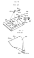
- An example of the radiation image read-out apparatus is shown in Figure 16.
- a stimulating light beam 101 a of a predetermined intensity is emitted from a stimulating light source 101 to impinge upon a light deflector such as a galvanometer mirror 102.
- the stimulating light beam 101a a is deflected by the galvanometer mirror 102 to impinge upon a stimulable phosphor sheet 103 positioned below the gaiva- nometer mirror 102 so that the stimulable phosphor sheet 103 is scanned by the stimulating light beam 101a a in the main scanning direction, i.e.. in the width direction of the sheet 103 as indicated by arrow A.
- the sheet 103 While the stimulating light beam 101a a impinges upon the stimulable phosphor sheet 103, the sheet 103 is conveyed in the sub-scanning direction as indicated by arrow B, for example, by an endless belt device 109. Therefore, scanning in the main scanning direction is repeated at an angle approximately normal to the sub-scanning direction, and the whole surface of the stimulable phosphor sheet 103 is two-dimensionally scanned by the stimulating light beam 101 a.
- the portion of the sheet 103 exposed to the stimulating light beam 101a a emits light having an intensity proportional to the stored radiation energy.
- the light emitted by the stimulable phosphor sheet 103 enters a transparent light guide 104 from its light input face 104a positioned close to the sheet 103 in parallel to the main scanning line.
- the light guide 104 has a flat-shaped front end portion 104b positioned close to the stimulable phosphor sheet 103 and is shaped gradually into a cylindrical shape towards the rear end side to form a substantially cylindrical rear end portion 104c which is closely contacted with a photomultiplier 105.
- the light entering the light guide 104 from its light input face 104a is guided inside of the light guide 104 by total internal reflection up to the rear end portion 104c, and is received by the photomultiplier 105 by way of a filter (not shown) which selectively transmits the light emitted by the stimulable phosphor sheet 103.
- a filter (not shown) which selectively transmits the light emitted by the stimulable phosphor sheet 103.
- the light emitted by the stimulable phosphor sheet 103 in proportion to the radiation energy stored therein is detected and converted into an electric image signal by the photomultiplier 105.
- the electric image signal thus obtained is sent to an image processing circuit 106 and processed therein.
- the electric image signal thus processed is then reproduced into a visible image and displayed, for example, on a CRT 7, or is stored in a magnetic tape 108.
- the light input face of the light guide must extend along the main scanning line, the light output end must be in such a shape as to permit connection to the photomultiplier having a small width. and the light guide must be uniform in width and thickness since light is transmitted through the light guide by total internal reflection. Accordingly, the light guide is formed by rolling an end portion of a rectangular light guide sheet material to conform to the shape of the photomultiplier as shown in Figure 17.
- the conventional light guide having such a shape is disadvantageous in that the dimension in the direction perpendicular to the light input face is large to enlarge the size of the overall radiation image read-out apparatus.
- the light guide for the radiation image read-out apparatus is formed of a bundle fiber comprising a plurality of optical fibers bundled into a flat plate shape
- the overall size of the apparatus can be reduced since the bundle fiber can be relatively freely deformed.
- the light input face of the bundle fiber is formed by a plurality of light input faces of the optical fibers forming the bundle fiber, the spaces which cannot contribute to transmission of light are formed between the light input faces of the respective optical fibers. Therefore, the light transmitting efficiency of the bundle fiber is as low as several percents and is 50 % at most, and the bundle fiber cannot be practically used for transmitting weak light.
- the bundle fiber is formed of a plurality of optical fibers as described above, the light transmitting efficiency substantially fluctuates in the light input face, and shading is generated at small intervals in each scanning line due to the fluctuation of the light transmitting efficiency. Since this shading is increased as the distance between the light input face of the bundle fiber and the scanning position is reduced, influence of the shading can be lowered by positioning the light input face of the bundle fiber at a large distance from the scanning position. However, when the distance between the scanning position and the light input face of the bundle fiber is enlarged, the amount of light entering the bundle fiber is inherently reduced. In the case where the reflected light is received by the bundle fiber, reduction in the amount of light can be compensated for by increasing the amount of the scanning light beam.
- the primary object of the present invention is to provide a light guide which is formed of a sheet-like light guide material to be able to be used as a light guide for the aforesaid radiation image read-out apparatus and can be small in size as measured in the direction perpendicular to the light input face thereof so that the overall size of the apparatus in which the light guide is to be incorporated can be reduced.
- a light guide comprising a plurality of strip-like light guide materials each of which has first and second end faces and which are arranged and connected together side by side at respective end portions including said first end faces so that the first end faces form a linearly extending light input face and are bent at respective intermediate portions so that respective the other end portions including said second end faces extend substantially in parallel to the light input face, said the other end portions of the respective strip-like light guide materials being superposed one on another and bundled so that the second end faces form a light output face in a plane substantially perpendicular to the light input face.
- a light guide comprising a light guide sheet material which has a linearly extending light input end face, a light output end face at an angle to the light input end face and an arcuate end face which joins the outer ends of the light input end face and the light output end faces and is convex outward, the arcuate end face being provided with a light reflecting layer, and said light guide sheet material being rolled about an axis substantially perpendicular to the light output end face with the light input face being positioned outer side of the roll.
- a light guide material 4' which may be, for instance, an acrylic sheet, has a uniform thickness of t, and has linearly extending front and rear end faces 4a' and 4d'.
- the portion 4c' of the light guide material 4' except the front end portion 4b' including the front end face 4a' is cut along a plurality of lines extending in perpendicular to the front end face 4a' to form a plurality of strip like portions which are five in number in this particular embodiment.
- the central strip-like portion is the largest in width w and the outermost strip-like portions are the smallest in width.
- the lengths I of the strip-like portions gradually increase from the right side to the left side.
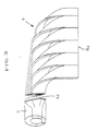
- the strip-like portions are bent rightward (toward the shortest strip-like portion) so that the rear end portions including the rear end faces 4d' extend in parallel to the front end face 4a' and the rear end portions are superposed one on another and bundled so that the rear end faces 4d' of the strip-like portions form a flat surface perpendicular to the front end face 4a', whereby a light guide 4 having a linearly extending light input face 4a and a light output face 4d perpendicular to the light input face 4a is formed as shown in Figure 2.
- the lengths of the strip-like portions are selected so that when the strip-like portions are bent to substantially the same extents, the rear end faces 4d' come to be flush with each other.
- the light input face 4a of the light guide 4 of this embodiment is positioned along the main scanning line and the light output face 4d is connected to a photodetector such as a photomultiplier.
- the width of the strip-like portions are gradually increased from the sides to the center as described above and accordingly, the shape of the light output face 4d approximates to a circle. This is advantageous in connecting the light output face 4d to the circular photomultiplier.
- the widths of all the strip-like portions may be equal to each other so that a rectangular light output face is formed.
- the light guide 4 of this embodiment In the light guide 4 of this embodiment, light emitted by the portion exposed to the scanning light beam enters the light guide from the light input face 4a with a high efficiency since the light input face 4a may be positioned close to the portion. Since the light guide 4 of this embodiment is formed of a sheet-like light guide material uniform in thickness and width, the light entering the light guide 4 travels inside of the light guide 4 by total internal reflection and reaches the light output face 4d with a high efficiency. Further, the size of the light guide 4 as measured in perpendicular to the light input face 4a is one third to a half of the conventional one since the light output face is formed in perpendicular to the light input face.
- the overall size of the apparatus in which the light guide is to incorporated can be reduced without deteriorating the light transmitting efficiency.
- the major part of light entering the light guide material described above are transmitted therethrough by total internal reflection, a very small part of the light is absorbed or leaks outside every time the light is reflected. Accordingly, as the length of the optical path in the light guide increases, the light transmitting efficiency is deteriorated by a small amount.
- the optical path for the light entering the light guide 4 from a portion near the photomultiplier is shorter than the that for the light entering the light guide from a portion remote from the photomultiplier, difference in the light transmitting efficiency can be produced.
- the difference is simple and corresponds to the shape of the light guide and does not change with age. Accordingly, the difference can be compensated for by, for instance, changing the position of junction to the photomultiplier according to the strip-like portions, or electrically adjusting the output of the photomultiplier.
- the light guide material 4' may be cut throughout the length as shown by the chain lines in Figure 1. In this case, boundary lines are produced on the light input face of the light guide, and the light transmitting efficiency is deteriorated at the boundary lines to cause shading. However, the shading can be electrically compensated for with ease. Further, the light input face and the light output face need not be strictly perpendicular to each other but may be slightly at an angle to each other so long as the size of the light guide as measured in perpendicular to the light input face can be reduced.
- the light guide in accordance with the present invention may be produced by molding of light guide material as shown in Figure 3.
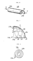
- the light guide 14 shown in Figure 3 is substantially the same as the light guide 4 shown in Figure 2 except that the widths of all the strip-like portions are the same and the rear end portions of the strip-like portions including the rear end faces are integrally formed into a block-like shape. Also the light guide 14 has a linearly extending light input face 14a and a light output face 14d perpendicular to the light input face 14a. When the light guide is integrally molded as in this embodiment, a plurality of light guides having a predetermined shape can be easily produced without polishing or the like.
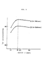
- Figure 5 shows relation between the radius and the light transmitting efficiency of the light guide 14 detected by connecting a photodetector to the light output face 14d.
- the light transmittivity of the material forming the light guide 14 is 91 %
- curve A in Figure 5 represents the relation in the case that the distance x between the light detecting side edge 14c of the light input face 14a and the light emitting position below the light input face 14a is 196mm
- curve B represents the relation in the case that the distance x is 368mm.
- the total internal reflection loss is abruptly increased as the radius r becomes smaller than a certain value, while the loss due to light absorption in the light guide is gradually increased due to increase in the length of the optical path.
- the light transmitting efficiency can be maximized by setting the radius r to about 18mm. Since the light transmitting efficiency of the conventional light guides shown in Figures 16 and 17 is generally 65%, the light transmitting efficiency of the light guide of this embodiment is equivalent to that of the conventional one.
- the bent portions of the strip-like portions is shaped to circumscribe a cylinder, the strip-like portions may be bent into other various shapes and may be bent into shapes different from each other.
- a reflecting mirror 16 be provided on the side of the scanning position opposite to the light input face 14a to reflect, toward the light input face 14a, light emitted from the sheet 3 and traveling away from the light input face 14a. Further, it is preferred that the light input face 14a and the reflecting mirror 16 be provided with an antireflection coating which prevents reflection of the stimulating light beam 1 a in order to prevent the stimulating light beam 1 a from being reflected by them after reflected by the sheet 3 to impinge upon a part of the sheet 3 deviated from the scanning position.
- the light output face 14d (Though the light output face 14d is practically connected to a photomultiplier, the photomultiplier is not shown in Figure 4.) be provided with a filter which transmits light emitted by the stimulable phosphor sheet 3 but absorbs the stimulating light beam.
- FIG 6 shows a light guide 25 in accordance with another embodiment of the present invention.
- the light guide 25 is formed by rolling a light guide sheet 25L shown in Figure 7.
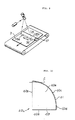
- the light guide sheet 25L is of a transparent acrylic sheet and is a quarter circle in shape in this particular embodiment.
- the light guide sheet 25L has first and second linear end faces 25a and 25b which extend in radial directions in perpendicular to each other, and an arcuate end face 25c joining the outer ends of the end faces 25a and 25b.
- the arcuate end face 25c is provided with a light reflecting layer 6 by, for instance, aluminum deposition.
- the light guide 25 of this embodiment is formed by rolling the sheet 25L about an axis C perpendicular to the end face 25b.
- the sheet 25L is rolled so that the outer side of the second linear end face 25b is positioned inside of the roll and the first linear end face 25a is positioned outside of the roll. As clearly shown in Figure 8, the end portion of the sheet 25L on the side of the first linear end face 25a extends linearly away from the outer surface of the portion positioned on the inner side of the end portion.
- the light guide 25 of this embodiment is used, for instance, in the aforesaid radiation image read-out apparatus in the manner shown in Figure 9. That is, the first linear end face 25a functions as the light input face and is disposed to extend along the main scanning line on the stimulable phosphor sheet 3.
- the second linear end face 25b which has been rolled into a circle functions as the light output face and is connected to a photodetector 37 such as a photomultiplier.
- Light 35 emitted by the stimulable phosphor sheet 3 upon stimulation enters the light guide 25 from the light input face 25a. As shown in Figure 7, a part of the light 15 entering the light guide 25 is reflected toward the light output face 25b by the arcuate end face 25c, and the other part of the light 15 directly travels to the light output face 25b. Since the light 15 emitted by the stimulable phosphor sheet 3 is nondirectionaf and the light 15 emitted from a certain point on the stimulable phosphor sheet 3 impinges upon the arcuate end face 25c at various angles. Since the arcuate end face 25c is of a quarter circle, the light impinging thereon at any angle is reflected toward the light output end face 25b.
- a light guide is formed by rolling a light guide sheet 40L comprising a quarter-circular portion 40e and a rectangular portion 40f integrally connected to one of the linear end faces of the quarter-circular portion 40e as shown in Figure 10.
- the light guide sheet 40L is rolled from the upper (as seen in Figure 10) side about an axis C.
- linear end faces 40a and 40b function respectively as the light input face and the light output face
- an arcuate end face portion 40c of the quarter-circular portion 40e and a linear end face 40d of the rectangular portion 40f are provided with a light reflecting layer 41.
- a light guide is formed by rolling a light guide sheet 50L which is a quarter- ellipsoid in shape as shown in Figure 11.
- the light guide sheet 50L is rolled from the upper (as seen in Figure 11) side about an axis C.
- linear end faces 50a and 50b function respectively as the light input face and the light output face, and an arcuate end face 50c is provided with a light reflecting layer 51.
- a light guide is formed by rolling a light guide sheet 60L which is a sector having an included angle larger than 90° in shape as shown in Figure 12.
- the light guide sheet 60L is rolled from the upper (as seen in Figure 12) side about an axis C. However. the portion below the broken line in Figure 12 is not rolled as shown in Figure 13.
- linear end faces 60a and 60b function respectively as the light input face and the light output face, and an arcuate end face 60c is provided with a light reflecting layer 61.
- a light guide is formed by rolling a light guide sheet 70L which is like a quarter of a doughnut in shape as shown in Figure 14.
- the light guide sheet 70L is rolled from the upper (as seen in Figure 14) side about an axis C.
- the portion below the broken line in Figure 14 is not rolled as shown in Figure 15, and accordingly, the photodetector 37 to be connected to the light guide can be positioned removed from the edge of the stimulable phosphor sheet 3.
- linear end faces 70a and 70b function respectively as the light input face and the light output face
- outer and inner arcuate end faces 70c and 70d are provided with a light reflecting layer 71.
- the light guides in accordance with the embodiments described above are formed by rolling a light guide sheet, they may be integrally formed, for instance, by injection molding. Further, the arcuate end joining the outer ends of the respective linear end faces may be of other various shapes, e.g., a part of a parabola, a part of a hyperbola, or the like.
Landscapes
- Physics & Mathematics (AREA)
- General Physics & Mathematics (AREA)
- Optics & Photonics (AREA)
- Radiography Using Non-Light Waves (AREA)
- Facsimile Scanning Arrangements (AREA)
Applications Claiming Priority (4)
| Application Number | Priority Date | Filing Date | Title |
|---|---|---|---|
| JP62070881A JP2566403B2 (ja) | 1987-03-25 | 1987-03-25 | 光ガイド |
| JP70881/87 | 1987-03-25 | ||
| JP150824/87 | 1987-06-17 | ||
| JP15082487A JPS63314504A (ja) | 1987-06-17 | 1987-06-17 | 光ガイド |
Publications (2)
| Publication Number | Publication Date |
|---|---|
| EP0284098A1 true EP0284098A1 (fr) | 1988-09-28 |
| EP0284098B1 EP0284098B1 (fr) | 1993-10-20 |
Family
ID=26412008
Family Applications (1)
| Application Number | Title | Priority Date | Filing Date |
|---|---|---|---|
| EP88104862A Expired - Lifetime EP0284098B1 (fr) | 1987-03-25 | 1988-03-25 | Guidage de lumière |
Country Status (3)
| Country | Link |
|---|---|
| US (1) | US4824194A (fr) |
| EP (1) | EP0284098B1 (fr) |
| DE (1) | DE3884986T2 (fr) |
Cited By (26)
| Publication number | Priority date | Publication date | Assignee | Title |
|---|---|---|---|---|
| FR2631460A1 (fr) * | 1988-05-11 | 1989-11-17 | Patiner Andre | Structure composee de guides de lumiere, ayant la forme d'une plaque de section particuliere |
| EP0838709A3 (fr) * | 1996-09-30 | 1999-07-28 | Siemens Aktiengesellschaft | Arrangement pour la transformation entre des rayons lumineux de section transversale mineur et un rayon lumineux de section transversale plus grande |
| WO2000033112A1 (fr) * | 1998-12-02 | 2000-06-08 | 3M Innovative Properties Company | Dispositif d'illumination et procede de fabrication de ce dispositif |
| US6614972B1 (en) | 1998-12-02 | 2003-09-02 | 3M Innovative Properties Company | Coupler for transporting and distributing light to multiple locations with uniform color and intensity |
| WO2005091026A1 (fr) * | 2004-03-15 | 2005-09-29 | Koninklijke Philips Electronics N.V. | Dispositif de guidage de lumiere et procede servant a guider la lumiere |
| WO2009048863A1 (fr) | 2007-10-09 | 2009-04-16 | Nichol Anthony J | Couplage de lumière dans des films éclairés |
| WO2010116320A1 (fr) * | 2009-04-10 | 2010-10-14 | Koninklijke Philips Electronics N.V. | Coude de guidage de lumière avec fentes incurvées |
| WO2012122511A1 (fr) | 2011-03-09 | 2012-09-13 | Flex Lighting Ii, Llc | Dispositif électroluminescent doté d'un profil de flux lumineux réglable |
| WO2012064519A3 (fr) * | 2010-11-08 | 2013-02-28 | 3M Innovative Properties Company | Convertisseur d'éclairage |
| US8434909B2 (en) | 2007-10-09 | 2013-05-07 | Flex Lighting Ii, Llc | Light emitting display with light mixing within a film |
| CN103672744A (zh) * | 2009-01-26 | 2014-03-26 | 弗莱克斯照明第二有限责任公司 | 通过柔性薄膜实现照明 |
| EP2558776A4 (fr) * | 2010-04-16 | 2014-05-21 | Flex Lighting Ii Llc | Dispositif d'éclairage frontal comprenant un guide de lumière basé sur un film |
| US8905610B2 (en) | 2009-01-26 | 2014-12-09 | Flex Lighting Ii, Llc | Light emitting device comprising a lightguide film |
| US8917962B1 (en) | 2009-06-24 | 2014-12-23 | Flex Lighting Ii, Llc | Method of manufacturing a light input coupler and lightguide |
| US9028123B2 (en) | 2010-04-16 | 2015-05-12 | Flex Lighting Ii, Llc | Display illumination device with a film-based lightguide having stacked incident surfaces |
| US9103956B2 (en) | 2010-07-28 | 2015-08-11 | Flex Lighting Ii, Llc | Light emitting device with optical redundancy |
| US9110200B2 (en) | 2010-04-16 | 2015-08-18 | Flex Lighting Ii, Llc | Illumination device comprising a film-based lightguide |
| US9566751B1 (en) | 2013-03-12 | 2017-02-14 | Flex Lighting Ii, Llc | Methods of forming film-based lightguides |
| US9690032B1 (en) | 2013-03-12 | 2017-06-27 | Flex Lighting Ii Llc | Lightguide including a film with one or more bends |
| US11442213B2 (en) | 2013-03-12 | 2022-09-13 | Azumo, Inc. | Film-based lightguide with extended coupling lightguide region |
| US11513274B2 (en) | 2019-08-01 | 2022-11-29 | Azumo, Inc. | Lightguide with a light input edge between lateral edges of a folded strip |
| US11966116B2 (en) | 2019-01-03 | 2024-04-23 | Azumo, Inc. | Reflective display comprising a lightguide and light turning film creating multiple illumination peaks |
| US11994698B2 (en) | 2018-08-30 | 2024-05-28 | Azumo, Inc. | Film-based frontlight with angularly varying diffusion film |
| US12135450B2 (en) | 2018-12-11 | 2024-11-05 | Azumo, Inc. | Method of manufacturing a display using a film-based lightguide and diffusely reflective release liner |
| US12262154B2 (en) | 2019-01-09 | 2025-03-25 | Azumo, Inc. | Reflective display comprising coupling lightguides folded at different fold angles |
| US12571956B2 (en) | 2020-09-29 | 2026-03-10 | Azumo, Inc. | Manufacturing a lightguide with cut lateral edges |
Families Citing this family (43)
| Publication number | Priority date | Publication date | Assignee | Title |
|---|---|---|---|---|
| US4952022A (en) * | 1989-03-02 | 1990-08-28 | Xerox Corporation | Fiber optic line illuminator with deformed end fibers and method of making same |
| US5058982A (en) * | 1989-06-21 | 1991-10-22 | Orbot Systems Ltd. | Illumination system and inspection apparatus including same |
| NL8902295A (nl) * | 1989-09-14 | 1991-04-02 | Philips Nv | Inrichting voor het langs optische weg aftasten van een dokument. |
| US5138161A (en) * | 1990-04-20 | 1992-08-11 | Fuji Photo Film Co., Ltd. | Apparatus for reading radiation image information |
| JP3270561B2 (ja) * | 1993-03-11 | 2002-04-02 | 富士写真フイルム株式会社 | 放射線画像読取装置 |
| US5381502A (en) * | 1993-09-29 | 1995-01-10 | Associated Universities, Inc. | Flat or curved thin optical display panel |
| US5455882A (en) * | 1993-09-29 | 1995-10-03 | Associated Universities, Inc. | Interactive optical panel |
| CA2134902C (fr) * | 1994-04-07 | 2000-05-16 | Friedrich Bertignoll | Diffuseur de lumiere |
| JPH09145943A (ja) * | 1995-11-28 | 1997-06-06 | Mitsubishi Gas Chem Co Inc | 曲がり光導波路およびその製造法 |
| US5724401A (en) * | 1996-01-24 | 1998-03-03 | The Penn State Research Foundation | Large angle solid state position sensitive x-ray detector system |
| US5754726A (en) * | 1996-05-31 | 1998-05-19 | Motorola, Inc. | Optical device assembly used for fastening to pc boards |
| JPH1073820A (ja) * | 1996-09-02 | 1998-03-17 | Dainippon Printing Co Ltd | 非光拡散性導光板、レンズフィルム、および面光源装置 |
| US5812714A (en) * | 1997-01-30 | 1998-09-22 | Cooper Industries, Inc. | Optical waveguide elements for a distributed lighting system |
| US6168302B1 (en) | 1997-12-09 | 2001-01-02 | Cooper Automotive Products, Inc. | Hybrid distributed lighting system for a vehicle |
| US6238074B1 (en) | 1997-12-09 | 2001-05-29 | Cooper Automotive Products, Inc. | Optical waveguide structures |
| US6186650B1 (en) | 1997-12-09 | 2001-02-13 | Cooper Automotive Products, Inc. | Vehicle headlamp with beamforming waveguide |
| US6164805A (en) * | 1998-04-20 | 2000-12-26 | Federal-Mogul World Wide, Inc. | Illuminated door handle for a vehicle |
| US6193399B1 (en) | 1997-12-09 | 2001-02-27 | Cooper Automotive Products, Inc. | Optical waveguide structures for vehicle lighting |
| WO1999066314A1 (fr) * | 1998-06-16 | 1999-12-23 | Orbotech Ltd. | Illuminateur pour l'inspection des surfaces sensiblement plates |
| US6139176A (en) * | 1998-07-02 | 2000-10-31 | Federal-Mogul World Wide, Inc. | Optical waveguide structure with raised or embedded waveguides |
| US6430339B1 (en) | 1998-10-15 | 2002-08-06 | Federal-Mogul World Wide, Inc. | Low profile waveguide system |
| IL131284A (en) | 1999-08-05 | 2003-05-29 | Orbotech Ltd | Illumination for inspecting surfaces of articles |
| US6327416B1 (en) * | 2000-01-24 | 2001-12-04 | Brookhaven Science Associates | Flexible optical panel |
| US6464404B1 (en) | 2000-06-19 | 2002-10-15 | Schott Fiber Optics, Inc. | Optical fiber rearrangement method and device |
| US6594437B1 (en) * | 2000-08-15 | 2003-07-15 | Fci Americas Technology, Inc. | Optical fiber separation and regrouping device |
| US6947655B2 (en) * | 2003-02-05 | 2005-09-20 | Schott Corporation | Ruggedized optical fiber rearrangement device |
| EP1508397B1 (fr) * | 2003-08-21 | 2006-06-07 | Leister Process Technologies | Procédé et dispositif pour la chauffe simultanée de matériaux |
| DE102008028829B4 (de) * | 2007-07-05 | 2017-10-19 | Johnson Controls Automotive Electronics Gmbh | Anzeigevorrichtung mit einem beleuchteten Zeiger mit geringem Helligkeitsverlust |
| EP2542939A4 (fr) * | 2010-03-02 | 2015-06-17 | Expoimaging Inc | Dispositif photographique formable |
| USD637344S1 (en) * | 2010-05-28 | 2011-05-03 | ExpoImaging, Inc. | Flexible multi-positionable rod support for light fixture |
| USD633647S1 (en) * | 2010-05-28 | 2011-03-01 | ExpoImaging, Inc. | Positionable reflector |
| USD637345S1 (en) * | 2010-05-28 | 2011-05-03 | ExpoImaging, Inc. | Flexible multi-positionable rod support for light fixture |
| USD632831S1 (en) * | 2010-05-28 | 2011-02-15 | Expolmaging, Inc. | Positionable reflector |
| USD637346S1 (en) * | 2010-05-28 | 2011-05-03 | ExpoImaging, Inc. | Flexible multi-positionable rod support for light fixture |
| USD637754S1 (en) * | 2010-05-28 | 2011-05-10 | ExpoImaging, Inc. | Positionable reflector |
| US20140049983A1 (en) * | 2010-11-18 | 2014-02-20 | Anthony John Nichol | Light emitting device comprising a lightguide film and aligned coupling lightguides |
| US8895935B2 (en) * | 2012-03-12 | 2014-11-25 | Hermes Microvision, Inc. | High efficiency secondary and back scattered electron detector |
| WO2013173151A1 (fr) * | 2012-05-16 | 2013-11-21 | 3M Innovative Properties Company | Convertisseur d'éclairage |
| US20150301267A1 (en) | 2012-12-05 | 2015-10-22 | 3M Innovative Properties Company | Anamorphic optical package |
| US20160003997A1 (en) * | 2013-02-14 | 2016-01-07 | 3M Innovative Properties Company | Assymetric input lightguide |
| US10520660B2 (en) | 2015-10-06 | 2019-12-31 | Corning Incorporated | Spatial multiplexing coupler for light guide plates |
| DE102016123958A1 (de) * | 2016-12-09 | 2018-06-14 | Eaton Industries (Austria) Gmbh | Lichtleiterplatte |
| CN106526969B (zh) * | 2016-12-27 | 2019-04-05 | 惠科股份有限公司 | 背光模块及其应用的显示设备 |
Citations (7)
| Publication number | Priority date | Publication date | Assignee | Title |
|---|---|---|---|---|
| US2825260A (en) * | 1954-11-19 | 1958-03-04 | O'brien Brian | Optical image forming devices |
| GB1250556A (fr) * | 1968-05-24 | 1971-10-20 | ||
| US3933556A (en) * | 1974-01-10 | 1976-01-20 | American Optical Corporation | Fiber optic image shape converter and method of making the same |
| US4026693A (en) * | 1974-02-16 | 1977-05-31 | Olympus Optical Co., Ltd. | Method for producing an image dissector |
| US4151582A (en) * | 1974-12-26 | 1979-04-24 | Izon Corporation | Point array sheet lighting apparatus |
| DE2736486B2 (de) * | 1976-08-13 | 1979-09-06 | Izon Corp., Stamford, Conn. (V.St.A.) | Optische Vorrichtung zur Aufzeichnung und zum Auslesen von Mikroinformation |
| DE2951501A1 (de) * | 1978-12-26 | 1980-07-17 | Fuji Photo Film Co Ltd | Strahlungsbildlesevorrichtung |
Family Cites Families (16)
| Publication number | Priority date | Publication date | Assignee | Title |
|---|---|---|---|---|
| US3544192A (en) * | 1968-02-29 | 1970-12-01 | Decitron Communication Systems | Shaped energy transmission arrays |
| US3718515A (en) * | 1970-06-29 | 1973-02-27 | Decicom Syst Inc | Process for manufacturing shaped energy transmission arrays |
| US4172631A (en) * | 1975-01-07 | 1979-10-30 | Izon Corporation | Parallel optical fiber and strip illuminating arrays |
| US4113348A (en) * | 1976-08-13 | 1978-09-12 | Izon Corporation | Channel illumination sheets |
| JPS5512429A (en) * | 1978-07-12 | 1980-01-29 | Fuji Photo Film Co Ltd | Radioactive image reader |
| US4315318A (en) * | 1978-12-26 | 1982-02-09 | Fuji Photo Film Co., Ltd. | Method and apparatus for processing a radiation image |
| US4485302A (en) * | 1978-12-26 | 1984-11-27 | Fuji Photo Film Co., Ltd. | Radiation image read out device |
| JPS55116340A (en) * | 1979-02-28 | 1980-09-06 | Fuji Photo Film Co Ltd | Method and device for processing gradation of radiation picture |
| JPS5611395A (en) * | 1979-07-11 | 1981-02-04 | Fuji Photo Film Co Ltd | Radiation image writeereading device |
| US4352550A (en) * | 1979-12-13 | 1982-10-05 | Iwatsu Electric Co., Ltd. | Combination of circular/straight line light beam scan transforming apparatus and optical device and method of fabricating circular/straight line transforming device |
| JPS56104645A (en) * | 1979-12-25 | 1981-08-20 | Fuji Photo Film Co Ltd | Radiation picture treating method and its device |
| NL8202698A (nl) * | 1982-07-06 | 1984-02-01 | Philips Nv | Inrichting voor het optisch aftasten van een document. |
| JPS5958744A (ja) * | 1982-09-27 | 1984-04-04 | Fuji Photo Film Co Ltd | シ−ト状集光体の遮光カバ− |
| US4530565A (en) * | 1982-12-20 | 1985-07-23 | The Perkin-Elmer Corporation | Optical transformer using curved strip waveguides to achieve a nearly unchanged F/number |
| US4671606A (en) * | 1985-03-22 | 1987-06-09 | Yevick George J | Dissecting optical viewer and recorder |
| US4748680A (en) * | 1986-08-08 | 1988-05-31 | Photon Devices, Ltd. | Color document scanner |
-
1988
- 1988-03-24 US US07/172,524 patent/US4824194A/en not_active Expired - Lifetime
- 1988-03-25 DE DE88104862T patent/DE3884986T2/de not_active Expired - Lifetime
- 1988-03-25 EP EP88104862A patent/EP0284098B1/fr not_active Expired - Lifetime
Patent Citations (7)
| Publication number | Priority date | Publication date | Assignee | Title |
|---|---|---|---|---|
| US2825260A (en) * | 1954-11-19 | 1958-03-04 | O'brien Brian | Optical image forming devices |
| GB1250556A (fr) * | 1968-05-24 | 1971-10-20 | ||
| US3933556A (en) * | 1974-01-10 | 1976-01-20 | American Optical Corporation | Fiber optic image shape converter and method of making the same |
| US4026693A (en) * | 1974-02-16 | 1977-05-31 | Olympus Optical Co., Ltd. | Method for producing an image dissector |
| US4151582A (en) * | 1974-12-26 | 1979-04-24 | Izon Corporation | Point array sheet lighting apparatus |
| DE2736486B2 (de) * | 1976-08-13 | 1979-09-06 | Izon Corp., Stamford, Conn. (V.St.A.) | Optische Vorrichtung zur Aufzeichnung und zum Auslesen von Mikroinformation |
| DE2951501A1 (de) * | 1978-12-26 | 1980-07-17 | Fuji Photo Film Co Ltd | Strahlungsbildlesevorrichtung |
Cited By (35)
| Publication number | Priority date | Publication date | Assignee | Title |
|---|---|---|---|---|
| FR2631460A1 (fr) * | 1988-05-11 | 1989-11-17 | Patiner Andre | Structure composee de guides de lumiere, ayant la forme d'une plaque de section particuliere |
| EP0838709A3 (fr) * | 1996-09-30 | 1999-07-28 | Siemens Aktiengesellschaft | Arrangement pour la transformation entre des rayons lumineux de section transversale mineur et un rayon lumineux de section transversale plus grande |
| WO2000033112A1 (fr) * | 1998-12-02 | 2000-06-08 | 3M Innovative Properties Company | Dispositif d'illumination et procede de fabrication de ce dispositif |
| US6614972B1 (en) | 1998-12-02 | 2003-09-02 | 3M Innovative Properties Company | Coupler for transporting and distributing light to multiple locations with uniform color and intensity |
| US6618530B1 (en) | 1998-12-02 | 2003-09-09 | 3M Innovative Properties Company | Apparatus for transporting and distributing light using multiple light fibers |
| WO2005091026A1 (fr) * | 2004-03-15 | 2005-09-29 | Koninklijke Philips Electronics N.V. | Dispositif de guidage de lumiere et procede servant a guider la lumiere |
| US7457509B2 (en) | 2004-03-15 | 2008-11-25 | Koninklijke Philips Electronics N.V. | Light-guiding device and a method of guiding light |
| CN100468101C (zh) * | 2004-03-15 | 2009-03-11 | 皇家飞利浦电子股份有限公司 | 光导设备和导光的方法 |
| WO2009048863A1 (fr) | 2007-10-09 | 2009-04-16 | Nichol Anthony J | Couplage de lumière dans des films éclairés |
| US8950902B2 (en) | 2007-10-09 | 2015-02-10 | Flex Lighting Ii, Llc | Light emitting device with light mixing within a film |
| EP2197649A4 (fr) * | 2007-10-09 | 2012-10-17 | Anthony J Nichol | Couplage de lumière dans des films éclairés |
| US8434909B2 (en) | 2007-10-09 | 2013-05-07 | Flex Lighting Ii, Llc | Light emitting display with light mixing within a film |
| US8905610B2 (en) | 2009-01-26 | 2014-12-09 | Flex Lighting Ii, Llc | Light emitting device comprising a lightguide film |
| CN103672744A (zh) * | 2009-01-26 | 2014-03-26 | 弗莱克斯照明第二有限责任公司 | 通过柔性薄膜实现照明 |
| WO2010116320A1 (fr) * | 2009-04-10 | 2010-10-14 | Koninklijke Philips Electronics N.V. | Coude de guidage de lumière avec fentes incurvées |
| US8917962B1 (en) | 2009-06-24 | 2014-12-23 | Flex Lighting Ii, Llc | Method of manufacturing a light input coupler and lightguide |
| EP2558776A4 (fr) * | 2010-04-16 | 2014-05-21 | Flex Lighting Ii Llc | Dispositif d'éclairage frontal comprenant un guide de lumière basé sur un film |
| US9028123B2 (en) | 2010-04-16 | 2015-05-12 | Flex Lighting Ii, Llc | Display illumination device with a film-based lightguide having stacked incident surfaces |
| US9110200B2 (en) | 2010-04-16 | 2015-08-18 | Flex Lighting Ii, Llc | Illumination device comprising a film-based lightguide |
| US9103956B2 (en) | 2010-07-28 | 2015-08-11 | Flex Lighting Ii, Llc | Light emitting device with optical redundancy |
| CN103201660A (zh) * | 2010-11-08 | 2013-07-10 | 3M创新有限公司 | 照明转换器 |
| WO2012064519A3 (fr) * | 2010-11-08 | 2013-02-28 | 3M Innovative Properties Company | Convertisseur d'éclairage |
| CN103201660B (zh) * | 2010-11-08 | 2016-01-20 | 3M创新有限公司 | 照明转换器 |
| US9645304B2 (en) | 2011-03-09 | 2017-05-09 | Flex Lighting Ii Llc | Directional front illuminating device comprising a film based lightguide with high optical clarity in the light emitting region |
| WO2012122511A1 (fr) | 2011-03-09 | 2012-09-13 | Flex Lighting Ii, Llc | Dispositif électroluminescent doté d'un profil de flux lumineux réglable |
| EP2683980A4 (fr) * | 2011-03-09 | 2014-08-13 | Flex Lighting Ii Llc | Dispositif électroluminescent doté d'un profil de flux lumineux réglable |
| US9566751B1 (en) | 2013-03-12 | 2017-02-14 | Flex Lighting Ii, Llc | Methods of forming film-based lightguides |
| US9690032B1 (en) | 2013-03-12 | 2017-06-27 | Flex Lighting Ii Llc | Lightguide including a film with one or more bends |
| US11442213B2 (en) | 2013-03-12 | 2022-09-13 | Azumo, Inc. | Film-based lightguide with extended coupling lightguide region |
| US11994698B2 (en) | 2018-08-30 | 2024-05-28 | Azumo, Inc. | Film-based frontlight with angularly varying diffusion film |
| US12135450B2 (en) | 2018-12-11 | 2024-11-05 | Azumo, Inc. | Method of manufacturing a display using a film-based lightguide and diffusely reflective release liner |
| US11966116B2 (en) | 2019-01-03 | 2024-04-23 | Azumo, Inc. | Reflective display comprising a lightguide and light turning film creating multiple illumination peaks |
| US12262154B2 (en) | 2019-01-09 | 2025-03-25 | Azumo, Inc. | Reflective display comprising coupling lightguides folded at different fold angles |
| US11513274B2 (en) | 2019-08-01 | 2022-11-29 | Azumo, Inc. | Lightguide with a light input edge between lateral edges of a folded strip |
| US12571956B2 (en) | 2020-09-29 | 2026-03-10 | Azumo, Inc. | Manufacturing a lightguide with cut lateral edges |
Also Published As
| Publication number | Publication date |
|---|---|
| DE3884986T2 (de) | 1994-02-17 |
| EP0284098B1 (fr) | 1993-10-20 |
| US4824194A (en) | 1989-04-25 |
| DE3884986D1 (de) | 1993-11-25 |
Similar Documents
| Publication | Publication Date | Title |
|---|---|---|
| US4824194A (en) | Light guide apparatus formed from strip light guides | |
| US4864134A (en) | Image read-out apparatus | |
| US4629890A (en) | Radiation image read-out apparatus | |
| EP0210505B1 (fr) | Dispositif lecteur pour un écran de phosphore stimulable | |
| US4829180A (en) | Radiation image read-out apparatus | |
| US4818880A (en) | Radiation image read-out apparatus | |
| US4739168A (en) | X-ray detector and method for manufacturing the same | |
| EP0144856B1 (fr) | Dispositif pour la reproduction d'image de rayonnement | |
| JPS60111238A (ja) | 放射線画像情報読取装置 | |
| EP0169965B1 (fr) | Dispositif pour la reproduction d'image de rayonnement | |
| US4661708A (en) | Radiation image read-out apparatus | |
| US4591715A (en) | Light guide member for radiation image read-out | |
| US4816688A (en) | Radiation image read-out apparatus for stimulable phosphor sheet | |
| US4970394A (en) | Apparatus for reading-out stimulable phosphor, radiographic recording elements | |
| US5455428A (en) | Photo detecting apparatus | |
| JP2566403B2 (ja) | 光ガイド | |
| US4835387A (en) | Radiation image read-out apparatus | |
| JPH05346509A (ja) | 集光ガイドおよびその製造方法 | |
| US5015852A (en) | Radiation image read-out apparatus | |
| US7042000B2 (en) | Radiation image read-out apparatus and stimulating light cut filter | |
| US4642462A (en) | Method of correcting radiation image read-out error | |
| JPH02228612A (ja) | 光ガイド | |
| US5753932A (en) | Photodetector system for radiation image read-out apparatus | |
| US4950904A (en) | Radiation image read-out apparatus | |
| JPH03209451A (ja) | 放射線画像情報読取装置 |
Legal Events
| Date | Code | Title | Description |
|---|---|---|---|
| PUAI | Public reference made under article 153(3) epc to a published international application that has entered the european phase |
Free format text: ORIGINAL CODE: 0009012 |
|
| AK | Designated contracting states |
Kind code of ref document: A1 Designated state(s): DE FR NL |
|
| 17P | Request for examination filed |
Effective date: 19881125 |
|
| 17Q | First examination report despatched |
Effective date: 19911004 |
|
| GRAA | (expected) grant |
Free format text: ORIGINAL CODE: 0009210 |
|
| AK | Designated contracting states |
Kind code of ref document: B1 Designated state(s): DE FR NL |
|
| REF | Corresponds to: |
Ref document number: 3884986 Country of ref document: DE Date of ref document: 19931125 |
|
| ET | Fr: translation filed | ||
| PLBE | No opposition filed within time limit |
Free format text: ORIGINAL CODE: 0009261 |
|
| STAA | Information on the status of an ep patent application or granted ep patent |
Free format text: STATUS: NO OPPOSITION FILED WITHIN TIME LIMIT |
|
| PG25 | Lapsed in a contracting state [announced via postgrant information from national office to epo] |
Ref country code: NL Effective date: 19941001 |
|
| 26N | No opposition filed | ||
| NLV4 | Nl: lapsed or anulled due to non-payment of the annual fee | ||
| PGFP | Annual fee paid to national office [announced via postgrant information from national office to epo] |
Ref country code: DE Payment date: 20070430 Year of fee payment: 20 |
|
| REG | Reference to a national code |
Ref country code: FR Ref legal event code: TP Ref country code: FR Ref legal event code: CD |
|
| PGFP | Annual fee paid to national office [announced via postgrant information from national office to epo] |
Ref country code: FR Payment date: 20070319 Year of fee payment: 20 |