EP0284423B1 - Appareil pour compter un nombre de pistes d'enregistrement applicable à un système de contrôle d'accés d'un disque optique - Google Patents
Appareil pour compter un nombre de pistes d'enregistrement applicable à un système de contrôle d'accés d'un disque optique Download PDFInfo
- Publication number
- EP0284423B1 EP0284423B1 EP88302687A EP88302687A EP0284423B1 EP 0284423 B1 EP0284423 B1 EP 0284423B1 EP 88302687 A EP88302687 A EP 88302687A EP 88302687 A EP88302687 A EP 88302687A EP 0284423 B1 EP0284423 B1 EP 0284423B1
- Authority
- EP
- European Patent Office
- Prior art keywords
- signal
- tracking
- phase
- track information
- track
- Prior art date
- Legal status (The legal status is an assumption and is not a legal conclusion. Google has not performed a legal analysis and makes no representation as to the accuracy of the status listed.)
- Expired - Lifetime
Links
Images




Classifications
-
- G—PHYSICS
- G11—INFORMATION STORAGE
- G11B—INFORMATION STORAGE BASED ON RELATIVE MOVEMENT BETWEEN RECORD CARRIER AND TRANSDUCER
- G11B7/00—Recording or reproducing by optical means, e.g. recording using a thermal beam of optical radiation by modifying optical properties or the physical structure, reproducing using an optical beam at lower power by sensing optical properties; Record carriers therefor
- G11B7/08—Disposition or mounting of heads or light sources relatively to record carriers
- G11B7/09—Disposition or mounting of heads or light sources relatively to record carriers with provision for moving the light beam or focus plane for the purpose of maintaining alignment of the light beam relative to the record carrier during transducing operation, e.g. to compensate for surface irregularities of the latter or for track following
-
- G—PHYSICS
- G11—INFORMATION STORAGE
- G11B—INFORMATION STORAGE BASED ON RELATIVE MOVEMENT BETWEEN RECORD CARRIER AND TRANSDUCER
- G11B7/00—Recording or reproducing by optical means, e.g. recording using a thermal beam of optical radiation by modifying optical properties or the physical structure, reproducing using an optical beam at lower power by sensing optical properties; Record carriers therefor
- G11B7/08—Disposition or mounting of heads or light sources relatively to record carriers
- G11B7/085—Disposition or mounting of heads or light sources relatively to record carriers with provision for moving the light beam into, or out of, its operative position or across tracks, otherwise than during the transducing operation, e.g. for adjustment or preliminary positioning or track change or selection
- G11B7/08505—Methods for track change, selection or preliminary positioning by moving the head
- G11B7/08541—Methods for track change, selection or preliminary positioning by moving the head involving track counting to determine position
-
- G—PHYSICS
- G11—INFORMATION STORAGE
- G11B—INFORMATION STORAGE BASED ON RELATIVE MOVEMENT BETWEEN RECORD CARRIER AND TRANSDUCER
- G11B7/00—Recording or reproducing by optical means, e.g. recording using a thermal beam of optical radiation by modifying optical properties or the physical structure, reproducing using an optical beam at lower power by sensing optical properties; Record carriers therefor
- G11B7/08—Disposition or mounting of heads or light sources relatively to record carriers
- G11B7/085—Disposition or mounting of heads or light sources relatively to record carriers with provision for moving the light beam into, or out of, its operative position or across tracks, otherwise than during the transducing operation, e.g. for adjustment or preliminary positioning or track change or selection
Definitions
- the present invention relates to an apparatus for counting the number of record tracks formed on an optical disc.
- the present invention relates particularly to the apparatus therefor applicable to an access control system used in a sample servo type optical disc apparatus.
- US-A-4405956 upon which the precharacterising portion of appended claim 1 is based, proposes an apparatus for use with a disk having positive and negative servo marks on the disk to provide sine and cosine head position signals.
- Sine and cosine signal approximations are generated from high frequency outputs of variable and fixed frequency oscillators and the same outputs are fed to the up and down inputs of a head actual position counter.
- an optical head is accessed onto a desired record track having a prerecorded address from one track.
- an optical head access driving portion including, e.g., a thread motor is driven in response to an access control signal CONT supplied from a system controller, so that the optical head traverses the record tracks.
- a pick-up signal PU derived from the optical head is inputted to a pick-up signal processing circuit.
- a tracking information S TRK is outputted from the pick-up signal processing circuit.
- the tracking information S TRK is periodically derived when the optical head traverses one of the record tracks is inputted into a track counting apparatus and the optical head access driving portion is driven until the counted contents of the track counting apparatus coincides with one of the tracks to the accessed.
- the record tracks TR (----TR n-1 , TR n ,TR n+1 ,----) formed on the optical disc have a servo area ERP and data recording area ERD , which are aligned in a radial direction, are alternatively conjoined in a sequential order on each same track. Therefore, the data recorded on the data recording area ERD do not interfere with the tracking information and clocking information recorded on the servo area.
- a pair of tracking pits PA , PB preformed in the servo area ERP are offset toward an inside and outside of a center line of the above-described record tracks by a 1/4 (one-fourth) pitch with respect to the center line CET of the above-described record tracks.
- a pit PC for a clocking signal is formed on the center line CET .
- the optical head can detect the three pits PA , PB , and PC as the change of reflected light beam from these pits.
- the pick-up signal derived at the optical head on the basis of the reflected light beam from the disc is sampled and held (sample/hold) by means of a sampling pulse generated by the pick-up signal processing circuit at a timing at which the read light beam LAR passes through the pits PA , PB , and PC .
- the pick up signal processing circuit can produce the tracking information representing a positional difference between the read light beam LAR and center line CET and produce clock information representing a timing at which the read light beam LAR has passed on the clocking signal pit PC .
- the system controller carries out a tracking control for the optical head so that the read light beam LAR scans the center line CET of the record tracks ---TR n-1 , TR n , TR n-1 ,--- on the basis of the tracking information derived in the pick-up signal processing circuit.
- the pick-up signal processing circuit generates a sampling pulse which is synchronized with the phase of the clocking information, so that the opto-magnetically recorded data on the data recording area ERD is sampled from the pick-up signal PU in accordance with the sampling pulse.
- the track counting apparatus counts the number of tracks which the read light beam has traversed on the basis of the tracking information S TRK transmitted from the pick-up signal processing circuit during the head access operation.
- a track transverse information INF TR sampled by means of the sampling pulse signal P S at a timing of the tracking signal pits PA and PB exhibits a change corresponding to one period of a sinusoidal wave during the time when the read light beam LAR is moved from one record track TR n to the other track TR n-1 (or TR n+1 ) at the outside (or inside) adjacent to the track TR n .
- a track transverse information INF TR constituted by a stepwise, sinusoidal waveform is obtained.
- the track transverse information INF TR is passed through a filter so that a clear phantom track transverse information INF TRX is derived. Therefore, the track counting apparatus can count the number of record tracks which the read light beam LAR has traversed by counting the number of times the track transverse information INF TR traverses a predetermined threshold level SHD on the basis of the change of the sampled track transverse information INF TR .
- the optical head gradually accelerates from a state in which the speed is zero during an accelerated transverse interval of time T1 immediately after the optical head has started, when the optical head accesses at a high speed one of the other tracks from a state during which the head is tracking one of the record tracks. Therefore, a period of the phantom track transverse information IN TRX (hence, the track transverse information INF TR ) is gradually reduced until the head enters a high-speed transverse interval at which the head moves at a high velocity.
- the sampling period of the sampling pulse used in the pick-up signal processing circuit is constant, the number of samplings per period of the track transverse interval information INF TR at an interval of the accelerated transverse T1 of the head are gradually reduced. Thereafter, at the high-speed transverse interval, a time axis is expanded so that the sampling periods ⁇ SP becomes substantially equal to one period ⁇ TRX of the phantom track transverse information INF TRX . consequently, a value of the track transverse information INF TR enters in a state in which, for example, only several numbers of sampling information can be extracted during one period of the above-described sampling.
- the track transverse information cannot be reproduced having the same contents of the phantom track transverse information INF TRX before the sampling from the track transverse information INF TR .
- the track transverse information INF TR exceeds the predetermined threshold level SHD , its reliability that the track transverse information INF TR represents the correct number of the traversed tracks becomes reduced.
- the above-described state has a relationship of a trajectory LARX of the read light beam LAR with respect to the record tracks TR .
- the read light beam LAR has traversed five record tracks TR n to TR n+4 while the trajectory LARX is passing through the data recording area ERD between the mutually adjoining servo areas ERP .
- only one sampling information can be obtained while the phantom track transverse information INF TRX changes by five periods.
- the read light beam LAR traverses the record tracks TR at a speed of 3 cm/sec. If the read light beam LAR traverses at a higher speed, the transverse track information cannot be reproduced in terms of the sampling theorem. Therefore, the information access speed from the optical disc is limited at a relatively slow speed value.
- an apparatus in an optical disc device for counting a number of traversed record tracks of a disc comprising: detecting means for providing first and second tracking information signals on the basis of information recorded on a disc; generating means for generating a first tracking signal following at least one of the frequency and the phase of the first track information signal and generating a second tracking signal following at least one of the frequency and the phase of the second track information signal; and fourth means for counting the number of tracks which the optical head has traversed on the basis of the first tracking signal and second tracking signal; characterised in that said detecting means comprises first means for providing a tracking error signal and second means for providing a clock reproduction signal on the basis of, respectively, first tracking pits and clocking pits previously formed on a disc in a discretely spaced apart manner, said first track information signal comprising said tracking error signal and said second track information signal comprising said clock reproduction signal.
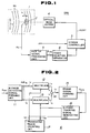
- Fig. 1 is a simplified circuit block diagram of an optical disc device to which an apparatus for counting a number of record tracks according to the present invention is applicable.
- Fig. 2 is a simplified circuit block diagram of the track counting apparatus according to the present invention for explaining a theoretical construction of the track counting apparatus shown in Fig. 1 .
- Fig. 3 is a simplified circuit block diagram of the track counting apparatus in a first preferred embodiment according to the present invention.
- Fig. 4 is a simplified circuit wiring diagram of a bi-phase detecting signal forming circuit shown in Fig. 2 .
- Fig. 5 is a simplified circuit wiring diagram of a traversed track count circuit shown in Fig. 3 .
- Fig. 6 is a simplified circuit wiring diagram of a bi-phase tracking signal generating circuit shown in Fig. 3 .
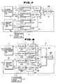
- Fig. 7 is a simplified circuit block diagram of the track counting apparatus in a second preferred embodiment.
- Fig. 8 is a simplified circuit block diagram of the track counting apparatus in a third preferred embodiment.
- Fig. 9 is a schematic timing chart for explaining a tracking operation for the optical disc.
- Fig. 10 is a schematic explanatory view of the optical disc and a trajectory of an optical head when the optical head accesses the record tracks at high speeds.
- Fig. 1 shows a whole optical disc device to which the present invention is applicable.
- Fig. 1 denotes the optical disc
- numeral 2 denotes an optical head
- numeral 3 denotes the system controller
- numeral 4 denotes the optical head driving portion
- numeral 5 denotes the pick up signal processing circuit
- numeral 6 denotes the track counting apparatus according to the present invention.
- Fig. 2 shows a whole circuit construction of the track counting apparatus 6 according to the present invention for explaining a basic concept of the present invention.
- a bi-phase detecting signal forming circuit 11 receives a track transverse information S TRK from the pick-up signal processing circuit 5 shown in Fig. 1 and outputs a first phase detecting signal V P and a second phase detecting signal V Q to multipliers 12 and 13 as a track transverse information INF TR .
- the multiplied outputs V A and V B are subtracted by a subtractor 14 .
- the subtracted output V C is converted into an analog control signal V CON of a direct current voltage output signal by means of an error signal forming circuit 15 .
- the control signal V CON is supplied to a bi-phase tracking signal generating circuit 16 .
- the bi-phase tracking signal generating circuit 16 includes a bi-phase voltage controlled oscillator (a bi-phase VCO ) and generates a first phase and second phase tracking signals V OP and V OQ constituted by sinusoidal waves having mutually different phases by 90°. These tracking signals are supplied to the multipliers 12 and 13 .
- a bi-phase VCO bi-phase voltage controlled oscillator
- the bi-phase detecting signal generating circuit 16 generates the first phase and second phase detecting signals V P and V Q having mutually different phases by 90° in the following on the basis of the transverse speed v of the optical head 2 .
- V P sin(2 ⁇ vt) (1)
- V Q cos(2 ⁇ vt) (2)
- V OQ sin(2 ⁇ vt+ ⁇ 0 ⁇ ) (4)
- the first phase tracking signal V OQ and second tracking signal V OP are signals whose phases are different in phase by ( ⁇ /2+ ⁇ 0 ⁇ ) from the corresponding first and second phase detecting signals V P and V Q .
- ⁇ 0 ⁇ denotes a minute phase difference.
- the subtracted output V C can be derived as a value approximate to the minute phase difference - ⁇ 0 ⁇ .
- the subtracted output is a signal having only a very low-frequency component (several kiloherz).
- the subtracted output V C is converted to a control signal V CON constituted by a direct current voltage in the error signal generating circuit 15 so as to control the oscillation frequency of the bi-phase tracking signal generating circuit 16 so that the minute phase difference ⁇ 0 ⁇ becomes zero.
- the bi-phase tracking signal generating circuit 16 is operated so as to behave a PLL (Phase Locked Loop) circuit to zero the substracted output V C .
- PLL Phase Locked Loop
- the first and second phase tracking signals V OP and V OQ are continued to be supplied to the multipliers 12 and 13 and transverse track counting circuit 17 .
- the first phase and second phase tracking signals V OP and V OQ of the bi-phase tracking signal generating circuit 16 are supplied to the transverse track counting circuit 17 .
- the tracking counting circuit 17 continues to count by one (increment) upon determination that the optical head 2 traverses one of the record tracks TR .
- the number of the traversed tracks are counted on the basis of the track signals V OP and V OQ comprising the continuous wave having the frequency and phase which follow those of the track transverse information INF TR . Therefore, even when a discrete sampling signal has reached as the track transverse information INF TR , the number of transverse tracks can be counted without error.
- the bi-phase tracking signal generating circuit 16 can change the oscillation frequency (hence, phase) at a response speed sufficiently fast as an electrical PLL loop. Hence, even if the frequency of the first phase detecting signal V P becomes extremely high, the bi-phase tracking signal generating circuit 16 follows the first phase tracking signal V P so as to oscillate at an extremely high oscillation frequency.
- the bi-phase tracking signal generating circuit 16 transmits the tracking signals V OP and V OQ of the continuous waves. Therefore, even if the discrete sampling information has arrived thereat as the track transverse information INF TR , the number of transverse tracks can accurately be counted.
- the subtracted output V C as a reference to control the bi-phase tracking signal generating circuit 16 includes only a low frequency component, the control of the bi-phase tracking signal generating circuit 16 can practically be facilitated.
- Fig. 3 shows a first preferred embodiment of the track counting apparatus 6 .
- the error signal forming circuit 15 supplies the sample/hold output V SPL of the sample/hold circuit 15A receiving the subtracted output V C to the bi-phase tracking signal generating circuit 16 as the control signal V CON via a low-pass filter 15B .
- the sample/hold circuit 15A receives a standard sample clock signal CK S (for example, a frequency of 41[kHz]) to sample the subtracted output V C having the same period as the sampling period sampling the track transverse information INF TR .
- CK S for example, a frequency of 41[kHz]
- the bi-phase detecting signal forming circuit 11 supplies detecting signals S11 , S12 , and S13 of the pick-up signal processing circuit 5 to the sample/hold circuits 11A , 11B , and 11C operating the sample clock signals CK A , CK B , and CK C .
- the pick-up signal processing circuit 5 samples the detecting signals S11 , S12 , and S13 corresponding to brightness of the reflected beam on the pits P A , P B and P C by means of the sample clock signals CK A , CK B , and CK C derived at a timing at which the read light beam sequentially irradiates the tracking signal pits PA and PB and the clocking signal pit PC and supplies them to the sample/hold circuits 11A , 11B , and 11C .
- the sample/hold circuit 11C for the clocking pit P C supplies the sampled and held output to the multiplier 13 shown in Fig. 3 as the second phase detecting signal v Q .
- the sampled and held outputs S 11A and S 11B of the sample/hold circuits 11A and 11B are supplied to an inverting input terminal and noninverting input terminal of an operational amplifier 11D having input resistors R11 , R12 , and R13 and feedback resistor R14 so that a tracking error signal as denoted by v p is produced at an output terminal of the operational amplifier 11D representing a relative positional offset of the tracking pits PA and PB with respect to the read light beam LAR .
- the tracking error signal is supplied to the multiplier 12 shown in Fig. 3 as the first phase detecting signal v p .
- the transverse track counting circuit 17 shown in Fig. 3 receives the first phase and second phase tracking signals V OP and V OQ transmitted from the bi-phase tracking signal generating circuit 16 at respective binary encoders 17A and 17B therein, as shown in Fig. 5 .
- the binary encoders 17A and 17B supply binary encoded outputs V OPD and V OQD whose levels rise to a logical high (" H ") level during a positive half period of the first and second tracking signals V OP and V OQ constituted by the sinusoidal wave to a clock input terminal CL of the track counter 17C and up/down control input terminal U/D .
- the track counting circuit 17C is controlled in an up-count (increment) operation state (or down-count (decrement) operation state) when the second binary coded output V OQD is at a logical high (" H ") level (or logical low (“ L ”) level).
- the track counter 17C counts up (increments) or counts down (decrements) depending on whether a rising edge of the first binary-coded output V OPD is at a logical high level or logical low level.
- This logical level represents a state in which the optical head 2 traverses in an inner direction or outer direction of the disc 1 .
- the counted contents of the track counter 17C are supplied to the system controller 3 of the optical disc device as the transverse track count output C TRV representing the number of tracks over which the read light beam LAR have traversed.
- the system controller 3 drives the optical head driving portion 4 according to the contents of the track count output C TRV .
- the bi-phase tracking signal generating circuit 16 in Fig. 3 includes a voltage controlled ocsillator ( VCO ) 16A which outputs an oscillated output S1 having a predetermined frequency range ,e.g., from 19 to 21 [ MHz ] according to the control signal V CON .
- the oscillated output S1 is multiplied by an oscillated output S2 having a predetermined frequency, e.g., 20 MHz generated in the oscillation circuit 16C by means of the multiplier 16B .
- the multiplied output S3 is supplied to a low-pass filter 16D having, e.g., a cut-off frequency of 20 [ MHz ].
- a frequency signal having a frequency (-1.00[ MHz ] to +1.0 [ MHz ]) difference between the oscillated outputs S1 and S2 is extracted from the multiplied output S3 and outputted as the first phase tracking signal V OP .
- the oscillated output S1 of the voltage-controlled oscillator 16A is multiplied by the frequency signal S4 derived via a 90-degree phase shifter 16F from the oscillated output S2 .
- the multiplied output S5 is supplied to a low-pass filter 16G having a cut-off frequency of 2 [ MHz ].
- a frequency signal having a frequency difference (-1.0 [ MHz ] to +1.0 [ MHz ] and a phase deviation of 90 degrees with respect to the first phase tracking signal V OP is outputted as the second phase tracking signal V OQ .
- the first phase and second phase tracking signals V OP and V OQ can thus be achieved which are constituted by continuous sinusoidal waves having a mutually phase difference of 90° and which are proportional to the control signal V CON transmitted from the error signal forming circuit 15 (refer to Fig. 3 ).
- the transverse speed of the optical head 2 rises from a state in which the optical head 2 is tracking one of the record tracks to a state in which the head 2 accesses the other record track is gradually increased from zero.
- the first phase and second phase tracking signals V OP and V OQ can be generated which accurately follow the positional change in a positive or negative direction of the control signal V CON derived from the error signal forming circuit 15 according to the changing transverse speed of the optical head 2 .
- the optical head 2 when the optical head 2 is started to access the other record track from one of the record tracks by means of the optical disc driving portion 4 , the optical head 2 starts traverse of the record track TR at an extremely low speed due to a mechanical inertia force at the initial stage from a time to .
- the transverse speed is increased in the gradually accelerated interval T1 shown in Fig. 9 such as the gradual increase in the acceleration (acceleration interval T1 as shown in Fig. 9 ) and ,thereafter, the constant, high-speed transverse (high speed transverse interval T2 as shown in Fig. 9 ).
- the detecting signals S11 , S12 , and S13 derived from the pits P A , P B , and P C are sampled by means of the sample/hold circuits 11A , 11B , and 11C in response to the standard sample clock signals CK A , CK B , and CK C , each having the same frequency as the standard sample clock signal CK S .
- the bi-phase detecting signal forming circuit 11 actually retrieves the multiple numbers of sampling information during a change of one period of a phantom track transverse information INF TRX as shown in ( B1 ) of Fig. 9 when the transverse speed of the read light beam LAR is very low. Therefore, the track transverse information INF TR substantially exhibiting the change of one period of the phantom track transverse information INF TRX can be sampled by means of the sample/hold circuits 11A , 11B , and 11C .
- the first phase and second phase detecting signals V P and V Q can be obtained having sinusoidal wave signals expressed in the equations ( 1 ) and ( 2 ) at output terminals of the bi-phase detecting signal forming circuit 11 .
- the subtracted output V C of the subtractor 14 represents a phase difference between the first and second phase tracking signals V OP and V OQ generated from the bi-phase tracking signal generating circuit 16 .
- the subtracted output V C has value corresponding to a minute difference - ⁇ 0 ⁇ representing a delay of the following operation of the bi-phase tracking signal generating circuit 16 and includes only low-frequency components.
- the sample/hold circuit 15A of Fig. 3 can sample and hold the subtracted output V C by means of the standard sample clock signal CK S and supply the control signal V CON according to the subtracted output V C .
- the bi-phase tracking signal generating circuit 16 generates the first phase and second phase tracking signals V OP and V OQ having phases (hence, frequency) following the change in the phases (hence, frequencies) of the first and second phase detecting signals V P and V Q so as to perform a follow-up operation to zero the subtracted output V C .
- the follow-up operation is executed during an acceleration interval T1 shown in Fig. 9 at which the speed of the optical head 2 becomes a constantly high.
- T1 the acceleration interval shown in Fig. 9 as denoted by T1
- the speed is in an interval of the high speed transverse interval T2
- the oscillation frequency of the bi-phase tracking signal generating circuit 16 is increased at a frequency substantially equal to the frequency at the high speed transverse interval T2 even if the frequencies of the first and second phase detecting signals V P and V Q become substantially equal to or shorter than the frequency of the standard sample clock signal CK S .
- the subtracted output V C of the subtractor 14 indicates the phase difference of - ⁇ 0 ⁇ between the first and second phase tracking signals V OP and V OQ whenever the first phase and second phase detecting signals v p and v q are sampled.
- the subtracted output V c is held by means of the sample/hold circuit 15A .
- the bi-phase signal tracking generating circuit 16 carries out the follow-up operation in response to the new incoming control signal V CON .
- the frequencies and phases of the first phase and second phase tracking signals V OP and V OQ are corrected whenever the first and second phase detecting signals V P and V Q are sampled so as to eliminate errors of the frequency and phase in the first and second phase detecting signals v p and v q .
- the first and second phase tracking signals V Op and V OQ having the frequencies and phases of the first and second phase detecting signals v p and v q and constituted by continuous waves can be obtained.
- the bi-phase tracking signal generating circuit 16 continues to output the first and second phase tracking signals V OP and V OQ in the continuous waveforms so as to compensate for the discrete detecting signals as the track transverse information INF TR even if only the discrete detecting signals as shown in Fig. 9 can be obtained as the track transverse information INF TR .
- the transverse tracking counting circuit 17 can count the number of the record tracks TR on which the optical head 1 traverses without error.
- Fig. 7 shows a second preferred embodiment of the track counting apparatus 6 .
- sample/hold circuit 15A of Fig. 3 is omitted in the error signal forming circuit 15 and in place of the sample/hold circuit 15A , sample/hold circuits 21A and 21B which sample the incoming signals v P and v Q in response to the standard sample clock signal CK S are connected to output terminals of the bi-phase detecting signal forming circuit 11 .
- other sample/hold circuits 21C and 21D are installed which operate in response to the standard sample clock signal CK S at output terminals of the first phase and second phase tracking signals V OP and V OQ of the bi-phase tracking signal generating circuit 16 .
- These sample/hold circuits 21C and 21D constitute a signal sampling circuit 21 .
- the bi-phase detecting signal forming circuit 11 provides the first phase and second phase detecting signals v P and v Q and carries out the sampling at a time of the standard sample clock signal CK S through the sample/hold circuits 21A and 21B .
- the first and second phase detecting signals v P and v Q retrieved discretely at a timing at which the read light beam LAR irradiates the tracking pits P A and P B and clocking signal pit P C are derived through the bi-phase detecting signal forming circuit 11 , as described above.
- the first and second phase tracking signals are retrieved into the sample/hold circuits 21A and 21B and at the same timing the first and second phase tracking signals V OP and V OQ are retrieved into the sample/hold circuits 21C and 21D .
- values sampled and held in the sample/hold circuits 21A and 21B represent positions between sequentially adjacent tracks TR on which the read light beam LAR irradiates (that is to say, a phase of the read light beam with respect to the track pitch).
- sampled and held values in the sample/hold circuits 21C and 21D represent the phases of the first and second phase tracking signals V OP and V OQ constituted by the sinusoidal waves outputted continously from the bi-phase tracking signal generating circuit 16 .
- the subtracted output V C derived from the multipliers 12 and 13 and subtractor 14 represents the phase difference ⁇ 0 ⁇ between the phases of the first phase detecting signals v P and v Q and those of the first and second phase tracking signals v OP and v OQ .
- the bi-phase tracking signal generating circuit 16 continues to generate the first and second phase tracking signals V OP and V OQ having the frequencies and phases following the first and second phase detecting signals v P and v Q .
- the track counting circuit 17 can reliably count the number of the traversed tracks on which the read light beam has traversed even if the frequencies of the first and second phase tracking signals V P and V Q become equal to or higher than that of the standard sample clock signal CK S due to high speed transverse of the read light beam on the record tracks.
- Fig. 8 shows a third preferred embodiment of the track counting apparatus 6 .
- an inverse tangent converting circuit 15C is installed as the error signal forming circuit 15 for forming an error signal V e corresponding to the phase difference ⁇ 0 ⁇ from the subtracted output V c derived from the subtractor 14 .
- the error signal forming circuit 15 derives the multiplied output V D indicating a multiplication of the sampled and held output V PX of the first phase detecting signal V P and sampled and held output V OQX of the second phase tracking signal V OQ by means of the multiplier 15D .
- the multiplier 15E multiplies the sampled and held output V QX of the second phase detecting signal V Q and sampled and held output V OPX of the first phase tracking signal V OP .
- the multiplied output V E is added to the multiplied output V D by means of an adder 15F and the added output V F is supplied to the inverse tangent converting circuit 15C .
- V OQX sin(2 ⁇ vt+ ⁇ 0 ⁇ ) (12)
- the subtracted output V C of the subtractor 14 can be expressed as follows:
- the added output V F of the adder 15F can be expressed as follows: If the inverse tangent converting circuit 15C executes the inverse tangent calculation on the basis of the added output V F and subtracted output V C , the error signal V e derived at an output terminal of the circuit 15C is expressed in the following way as the phase difference - ⁇ 0 ⁇ .
- the error signal V e representing the phase difference does not include the omitted calculation described above with reference to the equation ( 8 ) so that the bi-phase tracking signal generating circuit 16 can stably be in the PLL operation without influence of the large phase difference due to the large variation of, e.g., the tracking information S TRK .
- the tracking signals having the frequencies and phases following those of the track transverse information are generated and the number of tracks which the optical head traverses are counted using the tracking signal, a signal(s) having a continuous waveform(s) can be obtained as the tracking signal(s) even if a signal sampled discretely as the track transverse information has arrived at the counting apparatus.
- the transverse speed becomes remarkably increased, the number of tracks on which the optical head has traversed can be counted without error.
Landscapes
- Moving Of The Head For Recording And Reproducing By Optical Means (AREA)
- Optical Recording Or Reproduction (AREA)
- Indexing, Searching, Synchronizing, And The Amount Of Synchronization Travel Of Record Carriers (AREA)
- Moving Of Head For Track Selection And Changing (AREA)
Claims (6)
- Appareil dans un dispositif à disque optique pour compter un nombre de pistes d'enregistrement traversées d'un disque (1), l'appareil de comptage comprenant :
un dispositif de détection (5,11) pour fournir des premier et second signaux d'information de suivi de piste (VP, VQ) sur la base des informations enregistrées sur un disque ;
un dispositif de génération (16) pour générer un premier signal de suivi de piste (VOP) suivant au moins une des caractéristiques de fréquence et de phase du premier signal d'information de piste (VP) et pour générer un second signal de suivi de piste (VOQ) suivant au moins une des caractéristiques de fréquence et de phase du second signal d'information de piste (VQ) ; et
un quatrième dispositif (17) pour compter le nombre de pistes que la tête optique a traversées sur la base du premier signal de suivi de piste (VOP) du second signal du suivi de piste (VOQ) ;
caractérisé en ce que :
ledit dispositif de détection (5,11) comprend un premier moyen (11A, 11B, 11D) pour fournir un signal d'erreur de suivi de piste (VP) et un second dispositif (11C) pour fournir un signal de reproduction d'horloge (VQ) sur la base respectivement des premières cuvettes de suivi de piste (PA, PB) et des cuvettes d'horloge (PC) formés antérieurement sur un disque d'une manière espacée de façon discrète, ledit premier signal d'information de piste (VP) comprenant ledit signal d'erreur de suivi de piste (VP) et ledit second signal d'information de piste (VQ) comprenant ledit signal de reproduction d'horloge (VQ). - Appareil selon la revendication 1 dans lequel le second signal d'information de piste (VQ) est décalé en phase de π/2 par rapport au premier signal d'information de piste (VP).
- Appareil selon la revendication 1 ou 2, dans lequel un des signaux du premier signal de suivi de piste (VP) et du second signal de suivi de piste (VQ) est une entrée d'horloge d'un compteur progressif et dégressif constituant le quatrième dispositif (17) et l'autre signal des premier et second signaux de suivi de piste (VP, VQ) est une entrée de commande progressive/dégressive du compteur progressif/dégressif.
- Appareil selon la revendication 1, 2 ou 3 qui comprend en outre :(a) un premier dispositif de multiplication (12) recevant le signal d'information de piste (VP) et le premier signal de suivi de piste (VOP) et délivrant la sortie multipliée (VA) du signal d'information de piste (VP) et du premier signal de suivi de piste (VOP) ;(b) un second dispositif de multiplication (13) recevant le second signal d'information de piste (VQ) et le second signal de suivi de piste (VOQ) et délivrant la sortie multipliée (VB) du second signal d'information de piste (VQ) et du second signal de suivi de piste (VOQ) ; et(c) un soustracteur (14) qui soustrait mutuellement les sorties multipliées (VA, VB) des premier et second dispositifs de multiplication (12,13) le signal de sortie (VC) du soustracteur (14) représentant une première différence de phase entre le premier signal d'information de piste (VP) et le premier signal de suivi de piste (VOP) et entre le second signal d'information de piste (VQ) et le second signal de suivi de piste (VOQ) provoqué par une variation de la vitesse avec laquelle la tête optique traverse les pistes de piste et le signal de sortie (VC) du soustracteur (14) représentant la première différence de phase commandant le dispositif de génération (16) pour dériver le premier signal de suivi de piste (VOP) et le second signal de suivi de piste (VOQ).
- Appareil selon la revendication 4, dans lequel le signal de sortie (VC) du soustracteur (14) représentant la première différence de phase est échantillonné et maintenu et appliqué au circuit de génération du signal de suivi de piste (16) via un filtre passe-bas (15B).
- Appareil selon les revendications 1 ou 2, qui comprend en outre un soustracteur (14) recevant le signal de sortie d'un premier dispositif de multiplication (12) recevant le premier signal d'information de piste (VP) et le premier signal de suivi de piste (VOP) et le signal de sortie d'un second dispositif de multiplication (13) recevant le second signal d'information de piste (VQ) et le second signal de suivi de piste (VOQ), et un additionneur (15F) recevant le signal de sortie d'un troisième dispositif de multiplication (15D) recevant le premier signal d'information de piste (VP) et le second signal de suivi de piste (VOQ) et le signal de sortie d'un quatrième dispositif de multiplication (15E) recevant le second signal d'information de piste (VQ) et le premier signal de suivi de piste (VOP) et comprenant en outre un circuit de conversion arc tangente (15C) qui reçoit les sorties du soustracteur (14) et de l'additionneur (15F), le dispositif de génération (16) étant commandé par l'intermédiaire du signal de sortie (Vϑ) du circuit de conversion arc tangente (15C) pour dériver le premier signal de suivi de piste (VOP) et le second signal de suivi de piste (VOQ).
Priority Applications (1)
| Application Number | Priority Date | Filing Date | Title |
|---|---|---|---|
| AT88302687T ATE94677T1 (de) | 1987-03-25 | 1988-03-25 | Vorrichtung zum zaehlen einer anzahl von aufzeichnungsspuren, anwendbar auf einem zugriffskontrollsystem fuer eine optische platte. |
Applications Claiming Priority (2)
| Application Number | Priority Date | Filing Date | Title |
|---|---|---|---|
| JP72831/87 | 1987-03-25 | ||
| JP62072831A JPS63237269A (ja) | 1987-03-25 | 1987-03-25 | トラツクカウント装置 |
Publications (3)
| Publication Number | Publication Date |
|---|---|
| EP0284423A2 EP0284423A2 (fr) | 1988-09-28 |
| EP0284423A3 EP0284423A3 (en) | 1990-05-02 |
| EP0284423B1 true EP0284423B1 (fr) | 1993-09-15 |
Family
ID=13500754
Family Applications (1)
| Application Number | Title | Priority Date | Filing Date |
|---|---|---|---|
| EP88302687A Expired - Lifetime EP0284423B1 (fr) | 1987-03-25 | 1988-03-25 | Appareil pour compter un nombre de pistes d'enregistrement applicable à un système de contrôle d'accés d'un disque optique |
Country Status (6)
| Country | Link |
|---|---|
| US (1) | US5023855A (fr) |
| EP (1) | EP0284423B1 (fr) |
| JP (1) | JPS63237269A (fr) |
| KR (1) | KR880011756A (fr) |
| AT (1) | ATE94677T1 (fr) |
| DE (1) | DE3884027T2 (fr) |
Families Citing this family (6)
| Publication number | Priority date | Publication date | Assignee | Title |
|---|---|---|---|---|
| JPH02149932A (ja) * | 1988-11-30 | 1990-06-08 | Victor Co Of Japan Ltd | 光ディスク読取装置 |
| US5193081A (en) * | 1989-02-28 | 1993-03-09 | Kabushiki Kaisha Toshiba | Track-accessing controller for optical disks |
| DE3916462A1 (de) * | 1989-05-20 | 1990-11-22 | Thomson Brandt Gmbh | Verfahren zum spurspringen |
| JP2630151B2 (ja) * | 1992-01-30 | 1997-07-16 | 日本ビクター株式会社 | 光ディスク装置 |
| US5689485A (en) * | 1996-04-01 | 1997-11-18 | Discovision Associates | Tracking control apparatus and method |
| JPH11232662A (ja) * | 1998-02-13 | 1999-08-27 | Pioneer Electron Corp | 記録情報読取方法及び記録情報再生装置 |
Family Cites Families (10)
| Publication number | Priority date | Publication date | Assignee | Title |
|---|---|---|---|---|
| US4405956A (en) * | 1981-04-22 | 1983-09-20 | Xerox Corporation | Tracking apparatus for read/write head |
| US4402061A (en) * | 1981-10-15 | 1983-08-30 | Burroughs Corporation | Preformatted optical media for use in an optical memory system |
| KR880000999B1 (ko) * | 1981-11-25 | 1988-06-10 | 미쓰다 가쓰시게 | 광학적 정보 기억장치 |
| JPS5897138A (ja) * | 1981-12-04 | 1983-06-09 | Hitachi Ltd | 光スポットの位置検出方法及び光スポットの位置制御装置 |
| USRE32937E (en) * | 1982-03-19 | 1989-05-30 | Magnetic Peripherals, Inc. | Modulation system for optical recording |
| FR2528605B1 (fr) * | 1982-06-15 | 1987-11-20 | Thomson Csf | Procede et dispositif optique de focalisation d'un faisceau d'energie lumineuse sur un plan de reference d'un support d'information ainsi que ce support |
| EP0138947A1 (fr) * | 1983-03-07 | 1985-05-02 | Storage Technology Partners Ii | Systeme de detection de la position de rotation d'un disque rotatif ayant des pistes de recherches grossieres |
| JP2510410B2 (ja) * | 1983-10-27 | 1996-06-26 | パイオニア株式会社 | デイスクプレ−ヤの情報選択装置 |
| US4740940A (en) * | 1985-03-11 | 1988-04-26 | Matsushita Electric Industrial Co., Ltd. | Optical information read apparatus |
| FR2597248B1 (fr) * | 1985-11-27 | 1988-05-13 | Thomson Alcatel Gigadisc | Support d'information a pregravure et son dispositif d'exploration optiques a acces echantillonne |
-
1987
- 1987-03-25 JP JP62072831A patent/JPS63237269A/ja active Pending
-
1988
- 1988-03-18 US US07/170,352 patent/US5023855A/en not_active Expired - Fee Related
- 1988-03-24 KR KR1019880003155A patent/KR880011756A/ko not_active Ceased
- 1988-03-25 AT AT88302687T patent/ATE94677T1/de not_active IP Right Cessation
- 1988-03-25 DE DE88302687T patent/DE3884027T2/de not_active Expired - Fee Related
- 1988-03-25 EP EP88302687A patent/EP0284423B1/fr not_active Expired - Lifetime
Non-Patent Citations (1)
| Title |
|---|
| PATENT ABSTRACTS OF JAPAN, vol. 1, no. 73 (E-77)(845) 14 July 1977; & JP-A-52 10102 * |
Also Published As
| Publication number | Publication date |
|---|---|
| EP0284423A3 (en) | 1990-05-02 |
| ATE94677T1 (de) | 1993-10-15 |
| KR880011756A (ko) | 1988-10-31 |
| JPS63237269A (ja) | 1988-10-03 |
| US5023855A (en) | 1991-06-11 |
| DE3884027T2 (de) | 1994-02-03 |
| EP0284423A2 (fr) | 1988-09-28 |
| DE3884027D1 (de) | 1993-10-21 |
Similar Documents
| Publication | Publication Date | Title |
|---|---|---|
| US4271334A (en) | Apparatus for correcting for temperature-induced tracking errors in a system for recovering information from a recording disc | |
| US4067044A (en) | Information recording and retrieval apparatus | |
| US4494154A (en) | Pickup control device and method for fast or slow reproduction in a disk reading system | |
| NL8006268A (nl) | Platenspeler. | |
| EP0240678B1 (fr) | Commande de vitesse de rotation par modulation de largeur d'impulsion | |
| EP0306128B1 (fr) | Lecteur de disque et méthode d'exploration du disque | |
| EP0236944B1 (fr) | Procédé et système pour la reproduction des données enregistrées sur une disque mémoire | |
| US4481615A (en) | Motor controlling circuit of reproducing apparatus and method of controlling | |
| US5487055A (en) | Information recorder with tracking and seeking operations using low frequency tracking and lens position signals | |
| JPH10177724A (ja) | 光ディスク装置のビームスポット速度検出器 | |
| US5023855A (en) | Optical disc access control system that counts tracks using tracking control signal | |
| US6826135B2 (en) | Method of compensating for an eccentricity of an optical disk and apparatus for doing the same | |
| US5636196A (en) | Optical disc apparatus with selectively shiftable seek operation capture range | |
| US4769613A (en) | Digitalized amplitude detection circuit for analog input signal | |
| EP0375266A2 (fr) | Appareil pour l'enregistrement et/ou la reproduction de disques optiques | |
| EP0090420B1 (fr) | Appareil pour l'enregistrement optique et la reproduction d'information | |
| US4841511A (en) | Constant linear velocity disk rotating apparatus | |
| US4835753A (en) | Information playback system having an address search operation using a variable speed pickup positioning system | |
| EP0432278B1 (fr) | Dispositif de commande de positionnement | |
| JPH1186309A (ja) | 光ディスク制御装置 | |
| US5519678A (en) | Head seek control apparatus continuously detects and compensates for varying displacement velocity of optical head | |
| JPH0770179B2 (ja) | 光ディスク駆動装置 | |
| JPH05114257A (ja) | トラツクサーボ異常検出装置 | |
| JPH06187752A (ja) | 駆動装置 | |
| JPH11203702A (ja) | 光ディスク装置 |
Legal Events
| Date | Code | Title | Description |
|---|---|---|---|
| PUAI | Public reference made under article 153(3) epc to a published international application that has entered the european phase |
Free format text: ORIGINAL CODE: 0009012 |
|
| AK | Designated contracting states |
Kind code of ref document: A2 Designated state(s): AT DE FR GB |
|
| PUAL | Search report despatched |
Free format text: ORIGINAL CODE: 0009013 |
|
| AK | Designated contracting states |
Kind code of ref document: A3 Designated state(s): AT DE FR GB |
|
| 17P | Request for examination filed |
Effective date: 19900827 |
|
| 17Q | First examination report despatched |
Effective date: 19920123 |
|
| GRAA | (expected) grant |
Free format text: ORIGINAL CODE: 0009210 |
|
| AK | Designated contracting states |
Kind code of ref document: B1 Designated state(s): AT DE FR GB |
|
| REF | Corresponds to: |
Ref document number: 94677 Country of ref document: AT Date of ref document: 19931015 Kind code of ref document: T |
|
| REF | Corresponds to: |
Ref document number: 3884027 Country of ref document: DE Date of ref document: 19931021 |
|
| ET | Fr: translation filed | ||
| PGFP | Annual fee paid to national office [announced via postgrant information from national office to epo] |
Ref country code: FR Payment date: 19940310 Year of fee payment: 7 |
|
| PGFP | Annual fee paid to national office [announced via postgrant information from national office to epo] |
Ref country code: GB Payment date: 19940315 Year of fee payment: 7 |
|
| PGFP | Annual fee paid to national office [announced via postgrant information from national office to epo] |
Ref country code: AT Payment date: 19940325 Year of fee payment: 7 |
|
| PLBE | No opposition filed within time limit |
Free format text: ORIGINAL CODE: 0009261 |
|
| STAA | Information on the status of an ep patent application or granted ep patent |
Free format text: STATUS: NO OPPOSITION FILED WITHIN TIME LIMIT |
|
| 26N | No opposition filed | ||
| PGFP | Annual fee paid to national office [announced via postgrant information from national office to epo] |
Ref country code: DE Payment date: 19940929 Year of fee payment: 7 |
|
| PG25 | Lapsed in a contracting state [announced via postgrant information from national office to epo] |
Ref country code: GB Effective date: 19950325 Ref country code: AT Effective date: 19950325 |
|
| GBPC | Gb: european patent ceased through non-payment of renewal fee |
Effective date: 19950325 |
|
| PG25 | Lapsed in a contracting state [announced via postgrant information from national office to epo] |
Ref country code: FR Free format text: LAPSE BECAUSE OF NON-PAYMENT OF DUE FEES Effective date: 19951130 |
|
| PG25 | Lapsed in a contracting state [announced via postgrant information from national office to epo] |
Ref country code: DE Effective date: 19951201 |
|
| REG | Reference to a national code |
Ref country code: FR Ref legal event code: ST |