EP0284576A2 - Kompakter Gasentladungskolben und Verfahren zu seiner Herstellung - Google Patents
Kompakter Gasentladungskolben und Verfahren zu seiner Herstellung Download PDFInfo
- Publication number
- EP0284576A2 EP0284576A2 EP88850070A EP88850070A EP0284576A2 EP 0284576 A2 EP0284576 A2 EP 0284576A2 EP 88850070 A EP88850070 A EP 88850070A EP 88850070 A EP88850070 A EP 88850070A EP 0284576 A2 EP0284576 A2 EP 0284576A2
- Authority
- EP
- European Patent Office
- Prior art keywords
- limb
- glass
- tube
- main tube
- shaped
- Prior art date
- Legal status (The legal status is an assumption and is not a legal conclusion. Google has not performed a legal analysis and makes no representation as to the accuracy of the status listed.)
- Withdrawn
Links
Images


Classifications
-
- H—ELECTRICITY
- H01—ELECTRIC ELEMENTS
- H01J—ELECTRIC DISCHARGE TUBES OR DISCHARGE LAMPS
- H01J61/00—Gas-discharge or vapour-discharge lamps
- H01J61/02—Details
- H01J61/30—Vessels; Containers
- H01J61/32—Special longitudinal shape, e.g. for advertising purposes
- H01J61/325—U-shaped lamps
-
- H—ELECTRICITY
- H01—ELECTRIC ELEMENTS
- H01J—ELECTRIC DISCHARGE TUBES OR DISCHARGE LAMPS
- H01J9/00—Apparatus or processes specially adapted for the manufacture, installation, removal, maintenance of electric discharge tubes, discharge lamps, or parts thereof; Recovery of material from discharge tubes or lamps
- H01J9/24—Manufacture or joining of vessels, leading-in conductors or bases
- H01J9/26—Sealing together parts of vessels
- H01J9/265—Sealing together parts of vessels specially adapted for gas-discharge tubes or lamps
- H01J9/266—Sealing together parts of vessels specially adapted for gas-discharge tubes or lamps specially adapted for gas-discharge lamps
Definitions
- the present invention relates to a method for producing a compact gas discharge tube of the kind which comprises at least two U-shaped main tube components which are made of glass and which are mutually joined together at one limb thereof, to form a closed, continuous gas discharge chamber which is provided with electrodes at each outer end thereof and which has a layer of fluorescent or luminescent material provided on its inner glass surfaces.
- a method and a compact gas discharge tube of this kind are known from, e.g., European Patent Application 84113977.7.
- this known discharge tube, or envelope the ends of those limbs in which no electrode is fitted are sealed off prior to effecting the connection or juncture between the two U-shaped main components.
- This connection is effected in a manner similar to that described in British Patent Application 2 048 562 A, i.e. the tube wall is heated in the proximity of the end of the limb of one main component, so as to soften the glass, whereafter a tubular collar is blown out from the glass wall, perpendicularly thereto.
- a corresponding collar is then produced on the other main component of the discharge chamber in a similar manner, and the two collars are joined together by applying heat thereto, so as to form a short, narrow connecting tube.
- this known method may appear attractive from the aspect of manufacture, it has been found to have several drawbacks. For instance, the glass is not uniformly distributed during the glass softening stage of the process, thereby giving rise to stress concentrations and to the risk of fracture. Furthermore, the narrow connecting tube is liable to crack, both during manufacture and during use, not least when fitting the discharge tube, or envelope, onto its lamp fittings.
- the quality of the discharge tube is also impaired by the fact that the cross-sectional area of the connecting tube is much smaller than the cross-sectional area of the remainder of the discharge tube, which has a negative affect on the light emitting properties of the discharge tube.
- This is due to the fact that every constriction in the path of the gas discharge results in an increase in the total operating voltage and therewith in greater losses in the discharge path. Since this increase in losses does not result in a corresponding increase in light flux, it will only impair the efficiency of the discharge tube.
- the presence of constrictions in the discharge path results in a higher striking voltage, or starting voltage, which negatively affects the willingness of the discharge tube to ignite at low temperatures.
- the necessary cold zones are only produced at the outer end of the lamp incorporating such a discharge tube, which represents a disadvantage, since the gas discharge lamps must be capable of functioning irrespective of their orientation.
- the temperature at which the optimal mercury vapour pressure is engendered may prevail at the location where the discharge tube is connected to the lamp base.
- One object of the present invention is therefore to overcome the aforesaid drawbacks inherent with known methods for producing compact gas discharge tubes and with discharge tubes produced in accordance therewith. Another object is to provide a method of tube manufacture which is simpler and therewith more economic than known methods. A further object of the invention is to enable the wall thickness of the glass tubes from which the compact discharge tubes, or lamps, are made to be reduced without affecting the strength of the discharge tubes.
- the invention is based on the realization that the connection between U-shaped single tubes in a so-called multi-finger tube should also be given an essentially U-shape configuration and be connected directly to the straight limbs of the single tubes.
- a connection of this kind would overcome the aforementioned problems concerning illumination technique and mechanical strength.
- present day glass-blowing and glass-shaping techniques used for shaping the U-shaped bend in a single tube can not be used with multi-finger tubes, since in this case the space is restricted by the limb incorporating the cathode. Furthermore, it is, of course, always more difficult to orient and fixate the tubes in two planes than in a single plane.
- This problem is solved in accordance with the invention by using as starting material single tubes which have been suitably bevelled, instead of starting manufacture from standard straight tubes in accordance with conventional techniques.
- This enables the glass tubes to be joined end to end while heating the glass and bending the tubes to an appropriate U-shape, without unnecessarily concentrating glass in certain parts of the bend or tube areas adjacent thereto.
- the inventive compact tubes are produced from starting tubes in the form of long straight tubes 11 which have an outer diameter of 10-15 mm and a wall thickness of 0.9-1.4 mm.
- starting tubes which have an outer diameter of 12.0-12.5 mm and a wall thickness of 1.05-1.15 mm.
- the original starting tubes have a length of from 1 to 2 metres and are cut into shorter tube blanks 12, which are intended to form U-shaped main components 13, 13 ⁇ in the ultimate gas-discharge tube.
- the length of each tube blank 12 is determined by the desired size of the gas-discharge tube under production, and may vary widely, e.g. from 200 to 800 mm.
- the starting tubes 11 are cut alternately along lines which extend at right angles to the longitudinal axis 18 of respective tubes and obliquely to said axis.
- the tubes are preferably sawn with the aid of thin cutting discs, so as to avoid unnecessary waste and to produce as smooth edges as possible.
- the tube blanks 12 are then formed into the U-shaped main components 13, 13 ⁇ in a known manner and coated internally with a luminescent, fluorescent, substance.
- the tube areas at the free ends 14, 15 of the tubes are then brushed clean of fluorescent substance, so that said substance will not disturb subsequent treatment.
- the straight cut tube ends 14 are then fitted with an electrode 16 and an exhaust tube 17.
- the alternate oblique cuts, or saw cuts, are made along a line which is inclined at an angle of from 20° to 50° to the longitudinal axis 18 of the respective starting tubes 11.
- the tube blanks Prior to shaping the tube blanks 12 into the main tube components 13, the tube blanks are positioned so that the longitudinal normal plane 20 of the end surface 19 extends essentially at right angles to the main plane of the main tube component 13, as in the drawing plane of Figure 1.
- the glass gas-discharge tube 23 can be fitted with a lamp base and therewith form a complete compact gas-discharge tube, or lamp.
- connection 21 has a sufficiently large cross-sectional area and is not encumbered with pronounced irregularities or discontinuities.
- the connection should exhibit a continuous U-shape substantially free from variations in glass thickness or cross-sectional area.
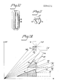
- the quantity of glass present in the connection 21, and therewith the wall thickness of the connection can be varied by appropriate selection of the angle of the oblique cut to the longitudinal axis 18 of the starting tubes 11. It will be seen from Figure 12 that the quantity of glass present in said connection becomes greater when the angle of bevel is decreased.
- W and W ⁇ identify the glass wall of the tube components 13, 13 ⁇ , and the hatched areas A indicate the amount of glass available for producing the actual bend 22.
- the most suitable bevel angle has been found to lie between 35-40°, which provides a compact gas-discharge tube having very good illuminating properties, from a technical aspect, and capable of being manufactured from thinner glass tube than those hitherto used in compact gas-discharge tubes of this kind, without impairing the mechanical strength of the tube.
- any selected number of U-shaped main tube components can be joined together in the aforedescribed manner.
- a six-finger tube, or envelope, comprising three main tube components 13, 13 ⁇ , 13 ⁇ is illustrated in Figures 10 and 11.
- the longitudinally extending normal planes 20 of the end surfaces 19 shall be oriented so as to extend outwardly from the major planes of respective main components at an angle of substantially 120°.
Landscapes
- Engineering & Computer Science (AREA)
- Manufacturing & Machinery (AREA)
- Manufacture Of Electron Tubes, Discharge Lamp Vessels, Lead-In Wires, And The Like (AREA)
- Vessels And Coating Films For Discharge Lamps (AREA)
Applications Claiming Priority (2)
| Application Number | Priority Date | Filing Date | Title |
|---|---|---|---|
| SE8701184A SE457760B (sv) | 1987-03-23 | 1987-03-23 | Foerfarande foer framstaellning av kompaktlysroer |
| SE8701184 | 1987-03-23 |
Publications (2)
| Publication Number | Publication Date |
|---|---|
| EP0284576A2 true EP0284576A2 (de) | 1988-09-28 |
| EP0284576A3 EP0284576A3 (de) | 1990-11-22 |
Family
ID=20367939
Family Applications (1)
| Application Number | Title | Priority Date | Filing Date |
|---|---|---|---|
| EP19880850070 Withdrawn EP0284576A3 (de) | 1987-03-23 | 1988-02-25 | Kompakter Gasentladungskolben und Verfahren zu seiner Herstellung |
Country Status (10)
| Country | Link |
|---|---|
| US (1) | US4881007A (de) |
| EP (1) | EP0284576A3 (de) |
| JP (1) | JPS6463242A (de) |
| CN (1) | CN88101485A (de) |
| DD (1) | DD268329A5 (de) |
| DK (1) | DK154888A (de) |
| FI (1) | FI881339A7 (de) |
| HU (1) | HU197117B (de) |
| NO (1) | NO881276L (de) |
| SE (1) | SE457760B (de) |
Cited By (6)
| Publication number | Priority date | Publication date | Assignee | Title |
|---|---|---|---|---|
| WO1995017002A3 (de) * | 1993-12-16 | 1995-08-10 | Dieter Strueber | Verfahren zur herstellung einer entladungslampe und entladungslampe daraus |
| WO1996010837A1 (en) * | 1994-10-03 | 1996-04-11 | Stt Badalex Limited | Low pressure gas discharge lamp |
| WO1996011885A1 (en) * | 1994-10-14 | 1996-04-25 | Stt Badalex Limited | Method and apparatus for producing a low pressure gas discharge lamp |
| EP1202324A1 (de) * | 2000-10-31 | 2002-05-02 | Ngk Insulators, Ltd. | Keramikgefäss für Hochleistungsentladungslampe |
| US6747411B2 (en) | 2000-11-22 | 2004-06-08 | Ngk Insulators, Ltd. | Ceramic envelope for high intensity discharge lamp |
| US6781311B2 (en) | 2000-10-31 | 2004-08-24 | Ngk Insulators, Ltd. | Ceramic envelope for intensity discharge lamp |
Families Citing this family (11)
| Publication number | Priority date | Publication date | Assignee | Title |
|---|---|---|---|---|
| USD334072S (en) | 1990-07-31 | 1993-03-16 | Toshiba Lighting & Technology Corporation | Fluorescent lamp |
| USD334244S (en) | 1991-12-26 | 1993-03-23 | Gte Products Corporation | Fluorescent lamp |
| DE9207139U1 (de) * | 1992-05-26 | 1992-07-16 | Patent-Treuhand-Gesellschaft für elektrische Glühlampen mbH, 8000 München | Quecksilberdampf-Niederdruckentladungslampe |
| JPH09504902A (ja) * | 1993-11-03 | 1997-05-13 | サイエンス アプリケーションズ インターナショナル コーポレイション | 電子ディスプレイデバイスの背面照明のための高効率紫外線バックライトシステム |
| GB2287022B (en) * | 1994-02-24 | 1997-11-12 | Mass Technology | Method of producing a low-pressure mercury vapour discharge lamp |
| US5541477A (en) * | 1994-11-30 | 1996-07-30 | Matsushita Electric Works R&D Laboratory, Inc. | Self ballasted compact fluorescent lamp |
| KR970046574U (ko) * | 1995-12-21 | 1997-07-31 | 컴팩트 형광 램프 | |
| JP3775548B2 (ja) * | 1998-10-16 | 2006-05-17 | 信越石英株式会社 | 溶接方法 |
| WO2006106645A1 (ja) * | 2005-04-01 | 2006-10-12 | Matsushita Electric Industrial Co., Ltd. | 二重螺旋状ガラス管の製造方法、蛍光ランプ用発光管及び蛍光ランプ |
| TWM351978U (en) * | 2008-05-06 | 2009-03-01 | Cai Cheng Technology Co Ltd | Fluorescent tube with plural curvy sections |
| DE102010063483B4 (de) * | 2010-12-20 | 2012-09-27 | Osram Ag | Niederdruck-Gasentladungslampen-Körper, Niederdruck-Gasentladungslampe und Verfahren zum Herstellen eines Niederdruck-Gasentladungslampen-Körpers |
Family Cites Families (8)
| Publication number | Priority date | Publication date | Assignee | Title |
|---|---|---|---|---|
| NL187138C (nl) * | 1979-04-03 | 1991-06-03 | Philips Nv | Werkwijze voor het vervaardigen van een lagedrukkwikdampontladingslamp. |
| JPS60100357A (ja) * | 1983-11-02 | 1985-06-04 | Mitsubishi Electric Corp | 低圧放電ランプ |
| DE8333920U1 (de) * | 1983-11-25 | 1985-05-02 | Patent-Treuhand-Gesellschaft für elektrische Glühlampen mbH, 8000 München | Kompakte niederdruckentladungslampe |
| WO1985004048A1 (fr) * | 1984-03-02 | 1985-09-12 | Mitsubishi Denki Kabushiki Kaisha | Lampe a decharge electrique a basse pression |
| DE3437212A1 (de) * | 1984-10-10 | 1986-04-17 | Patent-Treuhand-Gesellschaft für elektrische Glühlampen mbH, 8000 München | Einseitig gesockelte niederdruckentladungslampe |
| DE3603108A1 (de) * | 1986-02-01 | 1987-08-06 | Hans Erlenbach | Vorrichtung zum herstellen von formlingen aus aufgeschaeumtem kunststoff |
| US4745323A (en) * | 1986-02-26 | 1988-05-17 | Duro-Test Corporation | Compact fluorescent lamp with outer envelope |
| JPH0693753A (ja) * | 1992-09-11 | 1994-04-05 | Taisei Corp | 地下立体式駐車場 |
-
1987
- 1987-03-23 SE SE8701184A patent/SE457760B/sv not_active IP Right Cessation
-
1988
- 1988-02-25 EP EP19880850070 patent/EP0284576A3/de not_active Withdrawn
- 1988-03-08 US US07/165,503 patent/US4881007A/en not_active Expired - Fee Related
- 1988-03-21 FI FI881339A patent/FI881339A7/fi not_active IP Right Cessation
- 1988-03-22 CN CN198888101485A patent/CN88101485A/zh active Pending
- 1988-03-22 DD DD88313884A patent/DD268329A5/de not_active IP Right Cessation
- 1988-03-22 HU HU881439A patent/HU197117B/hu not_active IP Right Cessation
- 1988-03-22 DK DK154888A patent/DK154888A/da not_active IP Right Cessation
- 1988-03-22 JP JP63065977A patent/JPS6463242A/ja active Pending
- 1988-03-23 NO NO881276A patent/NO881276L/no unknown
Cited By (6)
| Publication number | Priority date | Publication date | Assignee | Title |
|---|---|---|---|---|
| WO1995017002A3 (de) * | 1993-12-16 | 1995-08-10 | Dieter Strueber | Verfahren zur herstellung einer entladungslampe und entladungslampe daraus |
| WO1996010837A1 (en) * | 1994-10-03 | 1996-04-11 | Stt Badalex Limited | Low pressure gas discharge lamp |
| WO1996011885A1 (en) * | 1994-10-14 | 1996-04-25 | Stt Badalex Limited | Method and apparatus for producing a low pressure gas discharge lamp |
| EP1202324A1 (de) * | 2000-10-31 | 2002-05-02 | Ngk Insulators, Ltd. | Keramikgefäss für Hochleistungsentladungslampe |
| US6781311B2 (en) | 2000-10-31 | 2004-08-24 | Ngk Insulators, Ltd. | Ceramic envelope for intensity discharge lamp |
| US6747411B2 (en) | 2000-11-22 | 2004-06-08 | Ngk Insulators, Ltd. | Ceramic envelope for high intensity discharge lamp |
Also Published As
| Publication number | Publication date |
|---|---|
| HU197117B (en) | 1989-02-28 |
| SE8701184L (sv) | 1988-09-24 |
| EP0284576A3 (de) | 1990-11-22 |
| SE457760B (sv) | 1989-01-23 |
| HUT46165A (en) | 1988-09-28 |
| NO881276L (no) | 1988-09-26 |
| DK154888D0 (da) | 1988-03-22 |
| SE8701184D0 (sv) | 1987-03-23 |
| DK154888A (da) | 1988-09-24 |
| DD268329A5 (de) | 1989-05-24 |
| JPS6463242A (en) | 1989-03-09 |
| FI881339A0 (fi) | 1988-03-21 |
| FI881339A7 (fi) | 1988-09-24 |
| CN88101485A (zh) | 1988-10-05 |
| US4881007A (en) | 1989-11-14 |
| NO881276D0 (no) | 1988-03-23 |
Similar Documents
| Publication | Publication Date | Title |
|---|---|---|
| US4881007A (en) | Compact gas discharge tube and a method for its manufacture | |
| CN1159652A (zh) | 两侧被挤压密封的灯 | |
| JPH06162996A (ja) | 高圧放電ランプ | |
| CN86105820A (zh) | 高压气体放电灯 | |
| EP0720208B1 (de) | Kreisförmige Fluoreszenzlampe | |
| HK91693A (en) | Compact low-pressure discharge lamp | |
| US7595592B2 (en) | Discharge lamp and method of making same | |
| JPH0255905B2 (de) | ||
| JPH10241633A (ja) | 誘電体バリア放電ランプ | |
| JPH06283145A (ja) | 両側を封着されたハロゲンランプ | |
| TWI363365B (en) | Discharge lamp | |
| US6121729A (en) | Metal halide lamp | |
| JP2001351576A (ja) | ショートアーク型超高圧放電ランプ及びその製造方法 | |
| JPH0115974B2 (de) | ||
| US4648850A (en) | Low-pressure arc discharge lamp having a common passageway and method of manufacturing same | |
| EP0121427A1 (de) | Kompakt-Fluoreszenzlampe mit metallischem Führungselement für die Entladung | |
| CN111105985B (zh) | 钨电极及其制备方法,以及采用该钨电极的高压放电灯 | |
| JPH0161217B2 (de) | ||
| JP2002042656A (ja) | 管球の封止方法および管球 | |
| JPH06302267A (ja) | 冷陰極蛍光ランプの電極の製造方法 | |
| JPS604361Y2 (ja) | 管球 | |
| JPH1140057A (ja) | 低圧水銀蒸気放電灯の製造方法 | |
| JPH0770303B2 (ja) | 放電灯 | |
| JP3463570B2 (ja) | 片口形メタルハライドランプおよびその製造方法 | |
| JPH0449741B2 (de) |
Legal Events
| Date | Code | Title | Description |
|---|---|---|---|
| PUAI | Public reference made under article 153(3) epc to a published international application that has entered the european phase |
Free format text: ORIGINAL CODE: 0009012 |
|
| AK | Designated contracting states |
Kind code of ref document: A2 Designated state(s): AT BE CH DE ES FR GB IT LI NL SE |
|
| PUAL | Search report despatched |
Free format text: ORIGINAL CODE: 0009013 |
|
| AK | Designated contracting states |
Kind code of ref document: A3 Designated state(s): AT BE CH DE ES FR GB IT LI NL SE |
|
| STAA | Information on the status of an ep patent application or granted ep patent |
Free format text: STATUS: THE APPLICATION IS DEEMED TO BE WITHDRAWN |
|
| 18D | Application deemed to be withdrawn |
Effective date: 19910523 |