EP0285001A2 - Métier à tisser à griffes - Google Patents
Métier à tisser à griffes Download PDFInfo
- Publication number
- EP0285001A2 EP0285001A2 EP88104717A EP88104717A EP0285001A2 EP 0285001 A2 EP0285001 A2 EP 0285001A2 EP 88104717 A EP88104717 A EP 88104717A EP 88104717 A EP88104717 A EP 88104717A EP 0285001 A2 EP0285001 A2 EP 0285001A2
- Authority
- EP
- European Patent Office
- Prior art keywords
- rapier
- guide
- drive wheel
- belt
- weaving machine
- Prior art date
- Legal status (The legal status is an assumption and is not a legal conclusion. Google has not performed a legal analysis and makes no representation as to the accuracy of the status listed.)
- Granted
Links
Images


Classifications
-
- D—TEXTILES; PAPER
- D03—WEAVING
- D03D—WOVEN FABRICS; METHODS OF WEAVING; LOOMS
- D03D47/00—Looms in which bulk supply of weft does not pass through shed, e.g. shuttleless looms, gripper shuttle looms, dummy shuttle looms
- D03D47/27—Drive or guide mechanisms for weft inserting
- D03D47/275—Drive mechanisms
- D03D47/276—Details or arrangement of sprocket wheels
-
- D—TEXTILES; PAPER
- D03—WEAVING
- D03D—WOVEN FABRICS; METHODS OF WEAVING; LOOMS
- D03D47/00—Looms in which bulk supply of weft does not pass through shed, e.g. shuttleless looms, gripper shuttle looms, dummy shuttle looms
- D03D47/27—Drive or guide mechanisms for weft inserting
- D03D47/271—Rapiers
- D03D47/272—Rapier bands
-
- D—TEXTILES; PAPER
- D03—WEAVING
- D03D—WOVEN FABRICS; METHODS OF WEAVING; LOOMS
- D03D47/00—Looms in which bulk supply of weft does not pass through shed, e.g. shuttleless looms, gripper shuttle looms, dummy shuttle looms
- D03D47/27—Drive or guide mechanisms for weft inserting
- D03D47/277—Guide mechanisms
Definitions
- the invention relates to a rapier weaving machine according to the preamble of claim 1.
- Rapier looms of the type mentioned are known several times.
- EP-PS 0 126 497 describes such a rapier weaving machine in which the entry belt engages with the drive wheel over part of the circumference, a block-shaped guide member holding the entry belt on the circumference of the drive wheel both at the beginning and at the end of the engagement .
- the end of the belt facing away from the gripper head is guided in a guide channel. It is very disadvantageous that the block-shaped guide elements are exposed to a great deal of heating and great wear due to the friction, which has a disadvantageous effect on the working accuracy and the service life.
- Rapier weaving machines are also known which work with non-perforated entry belts.
- a rapier weaving machine is known from CH-PS 652 764, in which the end of the belt facing away from the rapier head is firmly connected to a drive wheel, an entry belt being used which is not perforated, so that the force is introduced via the end of the belt and the belt one or more layers can be wound on the driving wheel.
- a complicated guiding device which contains a rope, the two ends of which are fastened to the drive wheel, and this several times the drive wheel is looped and is additionally guided over rollers which are arranged outside the drive wheel. These rollers serve on the one hand for tensioning the rope and on the other hand for deflecting the rope from a guide area on the circumference of the drive wheel to the top of the entry belt wound on the drive wheel.
- This guiding device is extremely complicated and requires additional driving forces in order to hold the entry belt on the driving wheel and because of the convoluted guiding and deflection of the rope.
- the object of the invention is to design a rapier weaving machine of the type mentioned at the outset in such a way that an increase in speed, for example to 1000 rpm, is possible, and yet simple guiding of the entry belt is ensured, which is subject to only slight wear and requires only low driving forces and which Absorbs centrifugal forces.
- the object is achieved according to the invention by the characterizing features of claim 1.
- the fact that the entry belt is perforated and driven in the circumferential direction by a toothed drive wheel, so that the introduction of force is practically given or received in the direction of movement of the gripper head and that the end of the belt facing away from the gripper head is fastened to a rotatable guide device means that the guide channels are not required Frictional forces, which not only benefits the protection of the entry belt, but also prevents the entry belt from lifting off the circumference of the drive wheel. This is particularly the case when, for example, the guide device is coupled to the drive wheel in terms of drive, so that the drive wheel does not have to exert any tensile or compressive forces for the section of the entry belt which faces away from the gripper head.
- the drive and the guidance of the entry belt is extremely low in friction, because the driving force and the centrifugal force due to the extent Directional engagement of the input belt and drive wheel and is taken up by the fastened end of the input belt with the rotating guiding device, whereby no wear occurs, which has an extremely favorable effect on the accuracy and long service life of the rapier weaving machine.
- the low friction forces reduce the driving forces required. A reduction in the driving forces is also promoted by only small moving masses. Ultimately, this all means that much higher speeds of up to 1000 rpm are possible, and practically without wear, which is synonymous with low-noise operation, increased lifespan of the rapier weaving machine and low vibrations.
- the guide device for the belt end of the input belt facing away from the gripper head can be an additional guide wheel according to claim 2. This can either be driven by the moving input belt, but the guide wheel is preferably coupled to the drive wheel in terms of drive. The inertia forces can be further reduced if the guide device is designed according to claim 3.
- An embodiment of the rapier weaving machine according to claim 4 is particularly advantageous since the drive wheel and thus the moving inertial forces can then be kept small.
- the guide device is arranged independently of the driving wheel, a further guide element is recommended.
- An embodiment of the rapier weaving machine according to claim 7 is particularly advantageous, since then a guide device that is independent of the driving wheel is not necessary.
- an embodiment according to claim 8 is advantageous.
- the guide member which is assigned to the drive wheel on the side of the gripper head, can be designed as a sliding guide according to claim 9.
- an embodiment according to claim 10 is more advantageous, as a result of which the friction between the input belt and the guide wheel is eliminated.
- An improvement in the drive between the guide wheel and the entry belt can be achieved by driving coupling of the guide wheel to the drive wheel, the guide wheel then also being able to serve to support the drive.
- These properties are further improved by an embodiment of the guide wheel according to claim 11.
- the guide wheel can interact with the perforation of the entry belt, which is intended for engagement with the drive wheel.
- an embodiment according to claim 12 is more advantageous since there is then a more subtle interaction between the guide wheel and the entry belt.
- the management properties of the management body can be improved by an embodiment according to claim 13 and / or 14.
- the rapier weaving machine can be equipped with a single weft insertion device which is effective from one side of the shed through the entire shed.
- the gripper heads can cover the same length of travel according to claim 16, or different paths according to claim 17. It is also possible that the rapier heads are inserted into the shed from both sides synchronously or out of phase. It is even possible that the rapier head that draws the weft thread into the shed is already in the retraction movement when the other rapier head takes over the weft thread. According to claim 18, it is also possible to insert a weft thread from each side of the shed, which are preferably connected to one another according to claim 19.
- the compressed air can simultaneously press the entry belt against a drive wheel, thereby counteracting the centrifugal force of the driven entry belt and thus ensuring that the entry belt is held securely on the drive wheel.
- the sliding guide can be limited to the area facing the gripper head, at which the entry belt leaves the driving wheel.
- An embodiment according to claim 22 is also advantageous, as a result of which a secure hold of the entry belt on the drive wheel is ensured. Since a friction-reducing air cushion is formed by the compressed air, such a guide element can advantageously be arranged along the entire area on which the entry belt rests on the drive wheel. This ensures a secure hold of the entry belt on the drive wheel, the compressed air preferably being able to be set such that the entry belt is in contact with the drive wheel despite the centrifugal force.
- the entry belt can be a smooth, continuous belt, but a perforated entry belt is advantageous, in which case an embodiment according to claim 24 is particularly advantageous and ensures that the entry belt rests securely on the drive wheel.
- An embodiment according to claim 25 is also particularly advantageous, as a result of which the guidance of the rapier head and the entry belt on the reed is improved.
- an embodiment according to claim 26 is advantageous.
- An embodiment according to claim 27 is also particularly expedient, since the compressed air supply at the individual consumer points can then be adjusted according to individual needs.
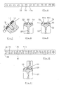
- FIG. 1 shows the parts of a rapier weaving machine that are essential to the present invention, in which 4 weft insertion devices 6, 8 are arranged on both sides of a shed formed by warp threads 2.
- the shed is in a manner known per se by shedding machines, not shown, such as formed by an electronically controlled jacquard machine over harness cords 9 and strands.
- these weft insertion devices 6, 8 have an identical structure.
- the weft insertion devices 6, 8 each contain a perforated, flexible entry belt 14, to one end of which the hook head 10 or 12 is fastened and the other end 16 of which is fastened, for example by means of a screw 18, to an alternately driven drive wheel 20.
- the drive wheel 20 thus simultaneously serves as a guide device 21 for the belt end 16 and moves it on a circular guide path during the entire working stroke.
- the drive wheel 20 contains teeth 22 distributed around its circumference, which engage in holes in the perforated flexible entry belt 14, as shown in detail in FIG.
- Such an entry belt can be designed, for example, according to FIGS. 6 and 10, as will be described in more detail below.
- a guide element 24 is assigned to the drive wheel 20, which is designed as a sliding guide or, as shown, as a guide wheel 26, which is also provided with teeth 28 on its circumference.
- the guide wheel 26 engages that area of the entry belt 14 which is assigned to the gripper head 10 or 12 and ensures that Entry belt 14 is in close engagement with the drive wheel 20 and does not lift off during the drive.
- the teeth 28 of the guide wheel 26 can have the same size as the teeth 22 of the drive wheel 20 and engage in the same holes in which the teeth 22 of the drive wheel 20 also engage, so that, for example, an entry belt 14a according to FIG Perforation 30 with holes 32 of the same size.
- the guide wheel 26 has teeth 28 which are smaller than the teeth 22 of the drive wheel 20 and an entry belt 14b is required for this, as shown in FIG. 10.
- Such an entry belt has a perforation 34 with a first row 35 with holes 36, which are intended for the teeth 22 of the drive wheel 20, and a second row 38 with holes 40, the size and spacing of which can be smaller than that of the holes 36 of the first Row 34, and which are intended to engage the teeth 28 of the guide wheel 26.
- the left weft insertion device 6 has a rapier head 10, which is fork-shaped and is used to grasp a weft 42, which is drawn off, for example, from a supply spool 44.
- the gripper head 12 of the right weft insertion device 8 is designed in the form of a hook and serves to take over the weft thread presented by the gripper head 10.
- the weft insertion devices are designed in such a way that the rapier heads 10, 12 are moved synchronously with respect to one another and each cross half the length of the shed 4 to the transfer point 46 at which the rapier Head 12 captures the weft 42 from the rapier head 10 and pulls it further through the shed to the other side of the same.
- both weft insertion devices 6, 8 are configured identically and their gripper heads 10, 12 each cover half the width of the shed 4 in their working stroke.
- the two weft insertion devices it is also entirely possible for the two weft insertion devices to have different working strokes, so that the transfer area follows can be shifted left or right in the shed.
- the movement sequences not to be synchronized with one another, but instead to be out of phase, with one of the gripper heads reaching the transfer area 46 in front of the other, for example. It is even possible to design the weft thread insertion devices in such a way that, for example, the looper head 10 already executes the retraction movement and is caught up in the looper head 12.
- weft insertion devices are designed differently and work according to a different principle, so that, for example, the right weft insertion device 8 of FIG. 1 can also be designed in accordance with that of Swiss patent application 3,644 / 86-7.
- FIG. 2 shows a further weft insertion device 48, in which a toothed driving wheel 50 with the radius r is assigned a guide device 52 in the form of a guide wheel 54 with the radius R, where R> r, to which the band end 56 of an entry band 58 is attached and is wound up in a circular guideway.
- the entry belt 58 is again from a toothed or toothless guide wheel 62 serving as a guide member 61 is guided to the drive wheel 50.
- a further guide wheel 64 on the entry belt 58 at the exit or entry area on the drive wheel 50.
- the guide wheels 54, 62, 64 can be free-running and can only be moved by the entry belt 58 driven by the drive wheel 50. However, it is also possible for the drive wheel 50 to drive the guide wheel 54, as is indicated by the toothed belt gear 66 shown in broken lines.
- the guide wheels 62, 64 can also be driven by a corresponding toothed belt transmission 68.
- FIG. 3 shows a further exemplary embodiment of a weft insertion device which is constructed similarly to that of FIG. 2, so that the same parts are provided with the same reference symbols.
- the drive roller 50 is assigned a guide arm 70 with the length or radius R, which is fastened to a shaft 72 at one end and the band end 56 at its other end 74 of the entry belt 58 carries along a circular guideway with the radius R.
- the drive wheel 50 is followed by a guide roller 76 which is attached to a support arm 78.
- the guide arm 70 could also be driven synchronously with the drive wheel 50 by means of a gear mechanism 80 indicated by dash-dotted lines.
- the guide wheel 62 can also be actuated synchronously by means of the toothed belt transmission 68 indicated by dash-dotted lines.
- FIG. 4 shows a further weft insertion device, which is constructed analogously to the weft insertion device 8 of FIG. 1, so that again the same parts are provided with the same reference numerals and reference is made to the explanations relating to FIG. 1.
- a second guide wheel 26a which is located on both sides of the entry point of the entry belt 14 on the drive wheel 20, is assigned to the guide member 24a for guiding the entry belt 14 on the drive wheel 20 in addition to a first guide wheel 26.
- the second guide wheel 26a is mounted on a rocker arm 82 which is mounted such that it can swing about the axis 84 of the guide wheel 26 and is biased by a spring 86 against the entry belt 14 or the drive wheel 20.
- FIG. 5 shows the right weft insertion device 8a of FIG. 1, but the guide member 24b is not designed as a guide wheel but as a slide guide 87.
- FIG. 6 shows the entry belt 14a already described above with the perforation 30 formed by the row of holes 32.
- the entry belt 14a can be fastened to the drive wheel 20 or to another guide device by means of the screw 18.
- the entry belt can also be connected to the drive wheel or to the guide device instead of the screw connection by means of an adhesive connection or in another suitable manner.
- an entry belt 14 can be helical in at least two rows 88a, 88b on the circumference 90 of a drive wheel 92, which at the same time acts as a guide device 93 for the tape end serves to be wound up.
- the drive wheel 92 has teeth 94 arranged in a helical path.
- the drive wheel 20 and the guide wheel 26, 26a can have teeth 22 and 28, respectively, which contain different sizes and distances and with separate rows 35, 38 interact from holes 36, 40 of corresponding size in the entry band 14b.
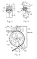
- FIG. 12 again shows the parts of a rapier weaving machine that are essential for the present invention, in which weft insertion devices 106, 108 are arranged on both sides of a shed 104 formed by warp threads 102.
- the shed is formed in a manner known per se by a shedding device, not shown.
- the weaving reed 109 is arranged in the shed for striking an inserted weft thread.
- the weft insertion devices 106, 108 have an identical structure with the exception of modified hook heads 110, 112.
- the weft insertion devices 106, 108 each contain a perforated flexible entry belt 114, at one end of which the hook head 110 or 112 is fastened and the other end of the belt 116 is fastened, for example by means of a screw 118, to an alternately driven drive wheel 120.
- the drive wheel 120 has teeth 122 distributed around its circumference, which engage in holes 124 of the perforated flexible entry belt 114, as shown in detail in FIG.
- a guide element 126 which is designed as a sliding guide, is assigned to the drive wheel 120.
- the guide member 106 shown in more detail in particular in FIG. 13, contains a slideway 128, in which compressed air outlet openings 130 are arranged, which are directed against the entry belt 114.
- a row of such compressed air outlet openings 130 is provided on both sides of the teeth 122.
- the compressed air outlet openings are connected via a feed line 132 to a compressed air source, not shown.
- a control valve 134 is arranged in the feed line 132, with which the compressed air supply to the guide member 126 can be adjusted.
- the rapier head 110 rests on a guide 136 in order to capture a thread 138 from a supply spool 140 and to insert it into the shed 104.
- the gripper head 110 conveys the thread 138 approximately to the middle of the shed, where it is taken over by the gripper head 112 of the second weft insertion device 108 and pulled out of the shed to the other side.
- the rapier heads 110, 112 are guided on a guide 142, which is arranged on the reed 109, as can be seen in particular from FIG.
- the stationary guide 136 and the guide 142 on the reed 109 in turn contain compressed air outlet openings 144 in order to reduce the friction of the rapier head and the entry belt when it is inserted into the shed.
- the compressed air outlet openings 144 are in turn connected via a feed line 146 to the compressed air source, not shown in detail.
- a control device 148 which contains a rotating cam disk 150 which actuates a valve 152.
- FIG. 15 shows a further exemplary embodiment, in which the end of the entry belt 114 is not fastened to the drive wheel 120, but the entry belt is only guided over part of the circumference of the drive wheel.
- the part 154 of the entry belt 114 facing away from the gripper head 112 leaves the drive wheel 120 and is guided in a further guide 156.
- a further guide member 158 is arranged, which is designed analogously to the guide member 126, which engages on the drive wheel 120 on the side facing the gripper head 112.
- the guide member 158 again contains compressed air outlet openings 160, which face the entry belt 114 and are connected to a compressed air source via a feed line 162.
- the two guide members 126, 158 can be designed in one piece and running over the entire wrap area of the entry belt 114 on the drive wheel 120.
- the entry belts for the rapier weaving machines can be designed in very different ways.
- they can be made of metal.
- plastic for example polyester, which are reinforced with fibers, preferably carbon fibers and / or glass fibers, are particularly advantageous.
- the entry belt is coated on both sides with fluoroplastic, ie Teflon R.
Landscapes
- Engineering & Computer Science (AREA)
- Textile Engineering (AREA)
- Looms (AREA)
Applications Claiming Priority (4)
| Application Number | Priority Date | Filing Date | Title |
|---|---|---|---|
| CH1296/87 | 1987-04-03 | ||
| CH129687 | 1987-04-03 | ||
| CH3847/87 | 1987-10-02 | ||
| CH384787 | 1987-10-02 |
Publications (3)
| Publication Number | Publication Date |
|---|---|
| EP0285001A2 true EP0285001A2 (fr) | 1988-10-05 |
| EP0285001A3 EP0285001A3 (fr) | 1992-04-29 |
| EP0285001B1 EP0285001B1 (fr) | 1994-08-03 |
Family
ID=25687234
Family Applications (1)
| Application Number | Title | Priority Date | Filing Date |
|---|---|---|---|
| EP88104717A Expired - Lifetime EP0285001B1 (fr) | 1987-04-03 | 1988-03-24 | Métier à tisser à griffes |
Country Status (6)
| Country | Link |
|---|---|
| US (1) | US5097873A (fr) |
| EP (1) | EP0285001B1 (fr) |
| JP (1) | JPH01502762A (fr) |
| DE (1) | DE3850899D1 (fr) |
| ES (1) | ES2058162T3 (fr) |
| WO (1) | WO1988007600A1 (fr) |
Cited By (10)
| Publication number | Priority date | Publication date | Assignee | Title |
|---|---|---|---|---|
| DE3916591A1 (de) * | 1988-05-27 | 1989-11-30 | Nuovo Pignone Spa | Verbessertes betriebssystem fuer flexible greiferbaender in schiffchenlosen webstuehlen |
| DE4035101A1 (de) * | 1989-11-03 | 1991-05-08 | Nuovo Pignone Spa | Verbessertes bandantriebssystem fuer den schussgreifer in einem schuetzenlosen webstuhl |
| EP0468916A1 (fr) * | 1990-07-24 | 1992-01-29 | Sulzer RàTi Ag | Métier à tisser à griffes avec lamelles de guidage des griffes |
| EP0726341A3 (fr) * | 1995-02-08 | 1996-11-13 | Toyoda Automatic Loom Works | Dispositif d'insertion de la trame dans un métier à tisser à griffes |
| EP0866156A1 (fr) * | 1997-03-20 | 1998-09-23 | Lindauer Dornier Gesellschaft M.B.H | Métier à tisser équipé d'un dispositif pour guider et supporter une lance porte-pince rigide |
| EP0905296A1 (fr) * | 1997-09-30 | 1999-03-31 | Kabushiki Kaisha Toyoda Jidoshokki Seisakusho | Dispositif d'insertion de la trame pour métiers à tisser à griffes |
| WO2000011249A1 (fr) * | 1998-08-25 | 2000-03-02 | Picanol N.V. | Metier a tisser a pinces comportant au moins une bande a pinces et des moyens de guidage |
| WO2000026454A1 (fr) * | 1998-10-29 | 2000-05-11 | Picanol N.V. | Bande a lance pour une lance d'une machine a tisser a lances, et machine a tisser a lances |
| EP1541730A1 (fr) * | 2003-12-09 | 2005-06-15 | m-tec Arbon AG | Métier à tisser |
| CN102912530A (zh) * | 2012-10-31 | 2013-02-06 | 常熟市常纺纺织机械有限公司 | 剑杆织机的剑杆与引剑轮的配合结构 |
Families Citing this family (6)
| Publication number | Priority date | Publication date | Assignee | Title |
|---|---|---|---|---|
| BE1009355A6 (nl) * | 1995-05-04 | 1997-02-04 | Picanol Nv | Grijperweefmachine met een grijper en een grijperband. |
| DE19538287C1 (de) * | 1995-10-14 | 1997-06-19 | Dornier Gmbh Lindauer | Webmaschine mit kühlbarem Greiferantrieb |
| US20090293983A1 (en) * | 2008-05-28 | 2009-12-03 | Itema (Switzerland) Ltd. | Apparatus And Method For The Insertion Of A Weft Thread In A Rapier Weaving Machine |
| JP2012197523A (ja) * | 2011-03-18 | 2012-10-18 | Toyosu Machinery Corp | レピア往復駆動装置 |
| BE1022754B1 (nl) * | 2015-02-26 | 2016-08-30 | Picanol Nv | Geleidingsinrichting voor een lans voor een grijperweefmachine |
| BE1027262B1 (nl) * | 2019-05-07 | 2020-12-08 | Vandewiele Nv | Geleidingsinrichting voor een grijperstang en grijperweefmachine omvattende een dergelijke geleidingsinrichting |
Family Cites Families (14)
| Publication number | Priority date | Publication date | Assignee | Title |
|---|---|---|---|---|
| DE54956C (de) * | P. A. BRENDGEN in Köln a. Rh., Humboldtstr. 1 | Selbsttätiger, mit Wasser betrie- ; bener Luftdruckapparat | ||
| DE642408C (de) * | 1934-12-31 | 1937-03-04 | Frederick John Trevallon Barne | Zapfvorrichtung fuer Bierfaesser und andere Fluessigkeitsbehaelter |
| DE638633C (de) * | 1935-01-05 | 1936-11-20 | Grossenhainer Webstuhl Und Mas | Mechanischer Greiferwebstuhl |
| US2641285A (en) * | 1950-11-28 | 1953-06-09 | Draper Corp | Method and mechanism for shutteless looms |
| US3159184A (en) * | 1962-11-13 | 1964-12-01 | Draper Corp | Tape motion for shuttleless looms |
| US3175587A (en) * | 1963-08-02 | 1965-03-30 | Draper Corp | Tape motion for shuttleless looms |
| DE1804973A1 (de) * | 1968-10-24 | 1970-05-27 | Stevens & Co Inc J P | Nadelwebstuhl |
| LU68217A1 (fr) * | 1973-08-13 | 1975-05-21 | ||
| CH596355A5 (fr) * | 1976-07-08 | 1978-03-15 | Rueti Ag Maschf | |
| US4252156A (en) * | 1979-01-08 | 1981-02-24 | Rockwell International Corporation | Tape control device for shuttleless looms |
| CH652764A5 (de) * | 1981-10-14 | 1985-11-29 | Rueti Ag Maschf | Vorrichtung fuer den schusseintrag an einer bandgreiferwebmaschine. |
| IT1151228B (it) * | 1982-05-25 | 1986-12-17 | Vamatex Spa | Disposizione di comando del moto delle pinze di trasporto della trama in telai di tessitura senza navette |
| DE3240972A1 (de) * | 1982-11-05 | 1984-05-10 | Shu-Lien Taipei Taiwan Liou | Verfahren zum speichern und ausnutzen der traegheit hin- und herschwingender elemente in schuetzenlosen webstuehlen |
| BE896771A (nl) * | 1983-05-18 | 1983-11-18 | Picanol Nv | Grijperaandrijving voor weefmachines. |
-
1988
- 1988-03-23 WO PCT/CH1988/000064 patent/WO1988007600A1/fr not_active Ceased
- 1988-03-23 US US07/582,983 patent/US5097873A/en not_active Expired - Lifetime
- 1988-03-23 JP JP63502385A patent/JPH01502762A/ja active Pending
- 1988-03-24 DE DE3850899T patent/DE3850899D1/de not_active Expired - Lifetime
- 1988-03-24 ES ES88104717T patent/ES2058162T3/es not_active Expired - Lifetime
- 1988-03-24 EP EP88104717A patent/EP0285001B1/fr not_active Expired - Lifetime
Cited By (18)
| Publication number | Priority date | Publication date | Assignee | Title |
|---|---|---|---|---|
| DE3916591A1 (de) * | 1988-05-27 | 1989-11-30 | Nuovo Pignone Spa | Verbessertes betriebssystem fuer flexible greiferbaender in schiffchenlosen webstuehlen |
| FR2631979A1 (fr) * | 1988-05-27 | 1989-12-01 | Nuovopignone Ind Mecganiche Fo | Systeme d'actionnement perfectionne pour les rubans flexibles des pinces de prehension des metiers a tisser sans navette |
| BE1003087A4 (fr) * | 1988-05-27 | 1991-11-19 | Nuovo Pignone Spa | Systeme d'actionnement perfectionne pour les rubans flexibles des pinces de prehension des metiers a tisser sans navette. |
| DE4035101A1 (de) * | 1989-11-03 | 1991-05-08 | Nuovo Pignone Spa | Verbessertes bandantriebssystem fuer den schussgreifer in einem schuetzenlosen webstuhl |
| EP0468916A1 (fr) * | 1990-07-24 | 1992-01-29 | Sulzer RàTi Ag | Métier à tisser à griffes avec lamelles de guidage des griffes |
| US5176185A (en) * | 1990-07-24 | 1993-01-05 | Sulzer Brothers Limited | Guide teeth for a rapier picking tape |
| EP0726341A3 (fr) * | 1995-02-08 | 1996-11-13 | Toyoda Automatic Loom Works | Dispositif d'insertion de la trame dans un métier à tisser à griffes |
| DE19711594A1 (de) * | 1997-03-20 | 1998-09-24 | Dornier Gmbh Lindauer | Vorrichtung zur Führung und Lagerung eines Greifertragorganes in Webmaschinen |
| EP0866156A1 (fr) * | 1997-03-20 | 1998-09-23 | Lindauer Dornier Gesellschaft M.B.H | Métier à tisser équipé d'un dispositif pour guider et supporter une lance porte-pince rigide |
| US5950686A (en) * | 1997-03-20 | 1999-09-14 | Lindauer Dornier Gesellschaft Mbh | Loom with a pneumatic slide bearing for supporting a rigid rod or a flexible band carrying a weft insertion gripper |
| EP1118699A1 (fr) * | 1997-03-20 | 2001-07-25 | Lindauer Dornier Gesellschaft M.B.H | Métier à tisser à griffes équipé d'un dispositif pour guider et supporter un organe porte-pince flexible |
| EP0905296A1 (fr) * | 1997-09-30 | 1999-03-31 | Kabushiki Kaisha Toyoda Jidoshokki Seisakusho | Dispositif d'insertion de la trame pour métiers à tisser à griffes |
| CN1071815C (zh) * | 1997-09-30 | 2001-09-26 | 株式会社丰田自动织机制作所 | 剑杆织机的引纬装置 |
| WO2000011249A1 (fr) * | 1998-08-25 | 2000-03-02 | Picanol N.V. | Metier a tisser a pinces comportant au moins une bande a pinces et des moyens de guidage |
| WO2000026454A1 (fr) * | 1998-10-29 | 2000-05-11 | Picanol N.V. | Bande a lance pour une lance d'une machine a tisser a lances, et machine a tisser a lances |
| BE1013013A3 (nl) * | 1998-10-29 | 2001-07-03 | Picanol Nv | Grijperband voor een grijperweefmachine. |
| EP1541730A1 (fr) * | 2003-12-09 | 2005-06-15 | m-tec Arbon AG | Métier à tisser |
| CN102912530A (zh) * | 2012-10-31 | 2013-02-06 | 常熟市常纺纺织机械有限公司 | 剑杆织机的剑杆与引剑轮的配合结构 |
Also Published As
| Publication number | Publication date |
|---|---|
| EP0285001A3 (fr) | 1992-04-29 |
| ES2058162T3 (es) | 1994-11-01 |
| EP0285001B1 (fr) | 1994-08-03 |
| JPH01502762A (ja) | 1989-09-21 |
| US5097873A (en) | 1992-03-24 |
| WO1988007600A1 (fr) | 1988-10-06 |
| DE3850899D1 (de) | 1994-09-08 |
Similar Documents
| Publication | Publication Date | Title |
|---|---|---|
| EP0285001B1 (fr) | Métier à tisser à griffes | |
| DE68916602T2 (de) | Vorrichtung zur Steuerung der Bewegung der Schusseintragsgreifer im Fach von schützenlosen Webmaschinen. | |
| EP0522100A1 (fr) | Metier a mailles jetees, en particulier machine a crocheter les galons. | |
| EP0352223B1 (fr) | Dispositif d'insertion de trame d'un métier à tisser à pinces | |
| DE2847520A1 (de) | Fadenvorlegevorrichtung, insbesondere zum vorlegen von kettfaeden fuer das automatische einziehen derselben in litzen und lamellen einer webmaschine | |
| EP2122024B1 (fr) | Dispositif de positionnement des fils à l'intérieur de la largeur de bande d'une section d'ourdissage et procédé d'ourdissage | |
| DE2312709C3 (de) | Vorrichtung für Webmaschinen mit ortsfest angeordneten Vorratsspulen zum Festhalten des Endes eines in das Webfach eingetragenen Schußfadens | |
| DE2659842C3 (de) | Webmaschine | |
| DE3001069C2 (fr) | ||
| WO1993006282A1 (fr) | Dispositif de pincement d'une couche de fils et son utilisation | |
| DE3105965A1 (de) | Webmaschine | |
| DE2724912C3 (de) | Webmaschine | |
| DE1535249B1 (de) | Fachbildevorrichtung fuer webmaschinen | |
| DE1535644B1 (de) | Schussfadenspeichervorrichtung fuer Webmaschinen mit Entnahme des Schussfadens von ausserhalb des Faches verbleibenden Schussfadenspulen | |
| DE120741C (fr) | ||
| CH646470A5 (de) | Duesenwebmaschine. | |
| DE10053651C1 (de) | Vorrichtung zum Einziehen von Kettfäden in ein Doppelwebblatt | |
| EP3438335A1 (fr) | Ros et métier à tisser circulaire | |
| DE2317233C3 (de) | Periodisch wirkende Fadenbremse | |
| DE2245407C3 (de) | Webmaschine mit zwei gegenläufig bewegten Greifern | |
| DE3643267C2 (de) | Vorrichtung zum maschinellen Bilden eines Fadenkreuzes in einer Fadenschar | |
| DE1953864C3 (de) | Vorrichtung zum Auftragen von mittels Schußfäden abgebundener Effektfäden auf ein Gewebe | |
| DE1535962C (de) | Vorrichtung zum Einlesen von Fadenkreuzen in Webketten | |
| CH473925A (de) | Webmaschine | |
| DE2938921A1 (de) | Einrichtung zum laden der schussfadentraeger von webmaschinen |
Legal Events
| Date | Code | Title | Description |
|---|---|---|---|
| PUAI | Public reference made under article 153(3) epc to a published international application that has entered the european phase |
Free format text: ORIGINAL CODE: 0009012 |
|
| AK | Designated contracting states |
Kind code of ref document: A2 Designated state(s): BE CH DE ES FR GB IT LI |
|
| 17P | Request for examination filed |
Effective date: 19881121 |
|
| PUAL | Search report despatched |
Free format text: ORIGINAL CODE: 0009013 |
|
| AK | Designated contracting states |
Kind code of ref document: A3 Designated state(s): BE CH DE ES FR GB IT LI |
|
| 17Q | First examination report despatched |
Effective date: 19930429 |
|
| GRAA | (expected) grant |
Free format text: ORIGINAL CODE: 0009210 |
|
| AK | Designated contracting states |
Kind code of ref document: B1 Designated state(s): BE CH DE ES FR GB IT LI |
|
| ET | Fr: translation filed | ||
| REF | Corresponds to: |
Ref document number: 3850899 Country of ref document: DE Date of ref document: 19940908 |
|
| ITF | It: translation for a ep patent filed | ||
| REG | Reference to a national code |
Ref country code: ES Ref legal event code: FG2A Ref document number: 2058162 Country of ref document: ES Kind code of ref document: T3 |
|
| GBT | Gb: translation of ep patent filed (gb section 77(6)(a)/1977) |
Effective date: 19941025 |
|
| PLBE | No opposition filed within time limit |
Free format text: ORIGINAL CODE: 0009261 |
|
| STAA | Information on the status of an ep patent application or granted ep patent |
Free format text: STATUS: NO OPPOSITION FILED WITHIN TIME LIMIT |
|
| 26N | No opposition filed | ||
| REG | Reference to a national code |
Ref country code: GB Ref legal event code: IF02 |
|
| PGFP | Annual fee paid to national office [announced via postgrant information from national office to epo] |
Ref country code: FR Payment date: 20060313 Year of fee payment: 19 |
|
| PGFP | Annual fee paid to national office [announced via postgrant information from national office to epo] |
Ref country code: CH Payment date: 20060315 Year of fee payment: 19 |
|
| PGFP | Annual fee paid to national office [announced via postgrant information from national office to epo] |
Ref country code: GB Payment date: 20060322 Year of fee payment: 19 |
|
| PGFP | Annual fee paid to national office [announced via postgrant information from national office to epo] |
Ref country code: ES Payment date: 20060329 Year of fee payment: 19 |
|
| PGFP | Annual fee paid to national office [announced via postgrant information from national office to epo] |
Ref country code: BE Payment date: 20060331 Year of fee payment: 19 |
|
| PGFP | Annual fee paid to national office [announced via postgrant information from national office to epo] |
Ref country code: DE Payment date: 20070316 Year of fee payment: 20 |
|
| REG | Reference to a national code |
Ref country code: CH Ref legal event code: PL |
|
| GBPC | Gb: european patent ceased through non-payment of renewal fee |
Effective date: 20070324 |
|
| BERE | Be: lapsed |
Owner name: *TEXTILMA A.G. Effective date: 20070331 |
|
| PG25 | Lapsed in a contracting state [announced via postgrant information from national office to epo] |
Ref country code: BE Free format text: LAPSE BECAUSE OF NON-PAYMENT OF DUE FEES Effective date: 20070331 |
|
| PGFP | Annual fee paid to national office [announced via postgrant information from national office to epo] |
Ref country code: IT Payment date: 20070613 Year of fee payment: 20 |
|
| REG | Reference to a national code |
Ref country code: FR Ref legal event code: ST Effective date: 20071130 |
|
| PG25 | Lapsed in a contracting state [announced via postgrant information from national office to epo] |
Ref country code: CH Free format text: LAPSE BECAUSE OF NON-PAYMENT OF DUE FEES Effective date: 20070331 Ref country code: LI Free format text: LAPSE BECAUSE OF NON-PAYMENT OF DUE FEES Effective date: 20070331 |
|
| PG25 | Lapsed in a contracting state [announced via postgrant information from national office to epo] |
Ref country code: GB Free format text: LAPSE BECAUSE OF NON-PAYMENT OF DUE FEES Effective date: 20070324 |
|
| REG | Reference to a national code |
Ref country code: ES Ref legal event code: FD2A Effective date: 20070326 |
|
| PG25 | Lapsed in a contracting state [announced via postgrant information from national office to epo] |
Ref country code: FR Free format text: LAPSE BECAUSE OF NON-PAYMENT OF DUE FEES Effective date: 20070402 Ref country code: ES Free format text: LAPSE BECAUSE OF NON-PAYMENT OF DUE FEES Effective date: 20070326 |