EP0285001B1 - Métier à tisser à griffes - Google Patents
Métier à tisser à griffes Download PDFInfo
- Publication number
- EP0285001B1 EP0285001B1 EP88104717A EP88104717A EP0285001B1 EP 0285001 B1 EP0285001 B1 EP 0285001B1 EP 88104717 A EP88104717 A EP 88104717A EP 88104717 A EP88104717 A EP 88104717A EP 0285001 B1 EP0285001 B1 EP 0285001B1
- Authority
- EP
- European Patent Office
- Prior art keywords
- gripper
- weaving machine
- guide
- machine according
- driving wheel
- Prior art date
- Legal status (The legal status is an assumption and is not a legal conclusion. Google has not performed a legal analysis and makes no representation as to the accuracy of the status listed.)
- Expired - Lifetime
Links
- 238000003780 insertion Methods 0.000 claims description 57
- 230000037431 insertion Effects 0.000 claims description 52
- 238000009941 weaving Methods 0.000 claims description 51
- 235000014676 Phragmites communis Nutrition 0.000 claims description 8
- 229920006362 Teflon® Polymers 0.000 claims description 2
- 229920002313 fluoropolymer Polymers 0.000 claims description 2
- 239000003365 glass fiber Substances 0.000 claims description 2
- 229920000728 polyester Polymers 0.000 claims description 2
- 239000004744 fabric Substances 0.000 claims 3
- OKTJSMMVPCPJKN-UHFFFAOYSA-N Carbon Chemical compound [C] OKTJSMMVPCPJKN-UHFFFAOYSA-N 0.000 claims 1
- 229920002430 Fibre-reinforced plastic Polymers 0.000 claims 1
- 229910052799 carbon Inorganic materials 0.000 claims 1
- 239000011151 fibre-reinforced plastic Substances 0.000 claims 1
- 239000000463 material Substances 0.000 claims 1
- 230000005540 biological transmission Effects 0.000 description 4
- 238000013461 design Methods 0.000 description 4
- 238000012546 transfer Methods 0.000 description 4
- 238000011161 development Methods 0.000 description 2
- 230000000694 effects Effects 0.000 description 2
- 230000006872 improvement Effects 0.000 description 2
- 230000003993 interaction Effects 0.000 description 2
- 229920000049 Carbon (fiber) Polymers 0.000 description 1
- 241001295925 Gegenes Species 0.000 description 1
- 239000004809 Teflon Substances 0.000 description 1
- 239000000853 adhesive Substances 0.000 description 1
- 230000001070 adhesive effect Effects 0.000 description 1
- 239000004917 carbon fiber Substances 0.000 description 1
- 230000008859 change Effects 0.000 description 1
- 238000001816 cooling Methods 0.000 description 1
- 230000008878 coupling Effects 0.000 description 1
- 238000010168 coupling process Methods 0.000 description 1
- 238000005859 coupling reaction Methods 0.000 description 1
- 230000002349 favourable effect Effects 0.000 description 1
- 210000003746 feather Anatomy 0.000 description 1
- 239000000835 fiber Substances 0.000 description 1
- 238000010438 heat treatment Methods 0.000 description 1
- 230000007246 mechanism Effects 0.000 description 1
- 239000002184 metal Substances 0.000 description 1
- 238000000034 method Methods 0.000 description 1
- 239000004033 plastic Substances 0.000 description 1
- 230000008569 process Effects 0.000 description 1
- 230000001737 promoting effect Effects 0.000 description 1
- 125000006850 spacer group Chemical group 0.000 description 1
- 238000004804 winding Methods 0.000 description 1
Images


Classifications
-
- D—TEXTILES; PAPER
- D03—WEAVING
- D03D—WOVEN FABRICS; METHODS OF WEAVING; LOOMS
- D03D47/00—Looms in which bulk supply of weft does not pass through shed, e.g. shuttleless looms, gripper shuttle looms, dummy shuttle looms
- D03D47/27—Drive or guide mechanisms for weft inserting
- D03D47/275—Drive mechanisms
- D03D47/276—Details or arrangement of sprocket wheels
-
- D—TEXTILES; PAPER
- D03—WEAVING
- D03D—WOVEN FABRICS; METHODS OF WEAVING; LOOMS
- D03D47/00—Looms in which bulk supply of weft does not pass through shed, e.g. shuttleless looms, gripper shuttle looms, dummy shuttle looms
- D03D47/27—Drive or guide mechanisms for weft inserting
- D03D47/271—Rapiers
- D03D47/272—Rapier bands
-
- D—TEXTILES; PAPER
- D03—WEAVING
- D03D—WOVEN FABRICS; METHODS OF WEAVING; LOOMS
- D03D47/00—Looms in which bulk supply of weft does not pass through shed, e.g. shuttleless looms, gripper shuttle looms, dummy shuttle looms
- D03D47/27—Drive or guide mechanisms for weft inserting
- D03D47/277—Guide mechanisms
Definitions
- the invention relates to a rapier weaving machine according to the preamble of claim 1.
- Rapier looms of the type mentioned are known several times.
- EP-A-0 126 497 describes such a rapier weaving machine in which the entry belt engages with the drive wheel over part of the circumference, with a block-shaped guide member at the beginning and at the end of the engagement, the entry belt on the circumference of the drive wheel holds. The end of the belt facing away from the gripper head is guided in a guide channel. It is very disadvantageous that the block-shaped guide elements are exposed to a great deal of heating and great wear due to the friction, which has a disadvantageous effect on the working accuracy and the service life.
- Rapier weaving machines are also known which work with non-perforated entry belts.
- a rapier weaving machine is known from CH-A-652 764, in which the end of the belt facing away from the rapier head is firmly connected to a drive wheel, an entry belt being used which is not perforated, so that the force is introduced via the end of the belt and that One or more layers of tape can be wound onto the drive wheel.
- the rapier weaving machine has resilient devices which are arranged in the movement end region of an oscillating member of the drive device for the entry belt in such a way that the kinetic energy of the oscillating member is absorbed and stored at the end of the oscillating movement of a working stroke of the entry belt on the resilient device in order to deliver the stored energy back to the oscillating link at the beginning of the oscillating movement in the opposite direction, ie at the next working stroke.
- the energy-storing device interferes with the control of the weaving machine when the drive conditions change.
- the object of the invention is to design a rapier weaving machine of the type mentioned at the outset in such a way that an increase in speed, for example to 1000 rpm. is possible and that a simple guiding of the entry belt is still guaranteed, which is subject to only slight wear and tear and requires only low driving forces and absorbs the centrifugal forces.
- the entry belt is perforated and driven by a toothed drive wheel in the circumferential direction, so that the introduction of force is practically given or received in the direction of movement of the gripper head and that the end of the belt facing away from the gripper head is fastened to a rotatable guide device of larger diameter connected downstream of the drive wheel , the drive wheel can be made particularly small and thus low in mass. Since the downstream guiding device does not have to cope with any driving forces, it can be relatively large and yet particularly light and therefore also low in mass, and the frictional forces required for guiding channels are also eliminated, which not only benefits the protection of the entry belt, but also the lifting of the entry belt from Circumference of the driving wheel prevented.
- the guide device for the belt end of the entry belt facing away from the gripper head can have an additional guide wheel according to claim 2. This can either be driven by the moving entry belt, but the guide wheel is preferably coupled to the drive wheel in terms of drive. The inertia forces can be further reduced if the guide device is designed according to claim 3.
- the guide device is arranged independently of the driving wheel, a further guide member is recommended.
- the guide member which is assigned to the drive wheel on the side of the gripper head, can be designed as a sliding guide according to claim 6.
- an embodiment according to claim 7 is more advantageous, as a result of which the friction between the entry belt and the guide wheel is eliminated.
- An improvement in the drive between the guide wheel and the entry belt can be achieved by driving coupling of the guide wheel to the drive wheel, the guide wheel then also being able to serve to support the drive.
- These properties are further improved by an embodiment of the guide wheel according to claim 8.
- the guide wheel can cooperate with the perforation of the entry belt, which is intended for engagement with the drive wheel.
- an embodiment according to claim 9 is more advantageous, since then there is a more subtle interaction between the guide wheel and the entry belt.
- the management properties of the management body can be improved by a configuration according to claim 10 and / or 11.
- the compressed air can simultaneously press the entry belt against a drive wheel, which counteracts the centrifugal force of the driven entry belt and thus ensures a secure hold of the entry belt on the drive wheel.
- the sliding guide can be limited to the area facing the gripper head, at which the entry belt leaves the driving wheel.
- An embodiment according to claim 19 is also advantageous, as a result of which a secure hold of the entry belt on the drive wheel is ensured. Since a friction-reducing air cushion is formed by the compressed air, such a guide element can advantageously be arranged along the entire area on which the entry belt rests on the drive wheel. This ensures a secure hold of the entry belt on the drive wheel, the compressed air preferably being able to be set such that the entry belt is in contact with the drive wheel despite the centrifugal force.
- An embodiment according to claim 22 is also particularly advantageous, as a result of which the guidance of the rapier head and the entry belt on the reed is improved.
- an embodiment according to claim 23 is advantageous.
- the drive wheel 20 contains teeth 22 distributed around its circumference, which engage in holes in the perforated, flexible entry belt 14, as shown in detail in FIG.
- Such an entry belt can be designed, for example, according to FIGS. 6 and 10, as will be described in more detail below.
- the drive wheel 20 is assigned a guide member 24, which is designed as a sliding guide or, as shown, as a guide wheel 26, which is also provided with teeth 28 on its circumference.
- the guide wheel 26 engages that area of the entry belt 14 which is assigned to the gripper head 10 or 12 and ensures that Entry belt 14 is in close engagement with the drive wheel 20 and does not lift off during the drive.
- the teeth 28 of the guide wheel 26 can have the same size as the teeth 22 of the drive wheel 20 and engage in the same holes in which the teeth 22 of the drive wheel 20 also engage, so that, for example, an entry belt 14a according to FIG Perforation 30 with holes 32 of the same size.
- the guide wheel 26 has teeth 28 which are smaller than the teeth 22 of the drive wheel 20 and an entry belt 14b is required for this, as shown in FIG. 10.
- Such an input belt has a perforation 34 with a first row 35 with holes 36, which are intended for the teeth 22 of the drive wheel 20, and a second row 38 with holes 40, the size and spacing of which can be smaller than that of the holes 36 of the first Row 34, and which are intended to engage the teeth 28 of the guide wheel 26.
- both weft insertion devices 6, 8 are configured identically and their gripper heads 10, 12 each cover half the width of the shed 4 in their working stroke.
- the two weft insertion devices it is also entirely possible for the two weft insertion devices to have different working strokes, so that the transfer area follows can be shifted left or right in the shed.
- the movement sequences do not take place synchronously with one another, but instead out of phase, one of the gripper heads for example reaching the transfer area 46 in front of the other.
- the weft thread insertion devices in such a way that, for example, the looper head 10 already executes the retraction movement and is caught in the looper head 12.
- the weft insertion devices are designed differently and work according to a different principle, so that, for example, the right weft insertion device 8 of FIG. 1 can also be designed in accordance with CH-A-671 412.
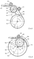
- FIG. 2 shows a further weft insertion device 48, in which a toothed driving wheel 50 with the radius r is assigned a guide device 52 in the form of a guide wheel 54 with the radius R, where R> r, to which the band end 56 of an entry band 58 is attached and is wound up in a circular guideway.
- the entry belt 58 is in turn by a toothed or toothless guide wheel 62 serving as a guide member 61 is guided to the drive wheel 50.
- a further guide wheel 64 on the entry belt 58 at the exit or entry area on the drive wheel 50.
- the guide wheels 54, 62, 64 can be free-running and can only be moved by the entry belt 58 driven by the drive wheel 50. However, it is also possible for the drive wheel 50 to drive the guide wheel 54, as is indicated by the toothed belt transmission 66 shown in broken lines.
- the guide wheels 62, 64 can also be driven by a corresponding toothed belt transmission 68.
- FIG. 4 shows a further weft insertion device, which is constructed analogously to the weft insertion device 8 of FIG. 1, so that again the same parts are provided with the same reference numerals and reference is made to the explanations relating to FIG. 1.
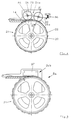
- a second guide wheel 26a which is located on both sides of the entry point of the entry belt 14 on the drive wheel 20, is assigned to the guide member 24a for guiding the entry belt 14 on the drive wheel 20 in addition to a first guide wheel 26.
- the second guide wheel 26a is mounted on a rocker arm 82 which is mounted such that it can swing about the axis 84 of the guide wheel 26 and is biased by means of a spring 86 against the entry belt 14 or the drive wheel 20.
- FIG. 5 shows the right weft insertion device 8a of FIG. 1, but the guide member 24b is not designed as a guide wheel but as a slide guide 87.
- FIG. 6 shows the entry belt 14a already described above with the perforation 30 formed by the row of holes 32.
- the entry belt 14a can be fastened to the drive wheel 20 or to another guide device by means of the screw 18.
- the entry belt can also be connected to the drive wheel or to the guide device instead of the screw connection by means of an adhesive connection or in another suitable manner.
- an entry belt 14 can be helical in at least two rows 88a, 88b on the circumference 90 of a drive wheel 92, which at the same time serves as a guide device 93 for the tape end serves to be wound up.
- the drive wheel 92 has teeth 94 arranged in a helical path.
- the drive wheel 20 and the guide wheel 26, 26a can have teeth 22 and 28, respectively, which contain different sizes and distances and with separate rows 35, 38 interact from holes 36, 40 of corresponding size in the entry band 14b.
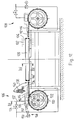
- FIG. 12 again shows a rapier weaving machine in which weft insertion devices 106, 108 are arranged on both sides of a shed 104 formed by warp threads 102.
- the shed is formed in a manner known per se by a shedding device, not shown.
- the weaving reed 109 is arranged in the shed for striking an inserted weft thread.
- the weft insertion devices 106, 108 have an identical structure.
- the weft insertion devices 106, 108 each contain a perforated flexible entry belt 114, at one end of which the hook head 110 or 112 is fastened and the other end of the belt 116 is fastened, for example by means of a screw 118, to an alternately driven drive wheel 120.
- the drive wheel 120 contains teeth 122 distributed around its circumference, which engage in holes 124 of the perforated, flexible entry belt 114, as shown in detail in FIG.
- a guide element 126 which is designed as a sliding guide, is assigned to the drive wheel 120.
- the guide member 106 shown in more detail in particular in FIG. 13, contains a slideway 128, in which compressed air outlet openings 130 are arranged, which are directed against the entry belt 114.
- a row of such compressed air outlet openings 130 is provided on both sides of the teeth 122.
- the compressed air outlet openings are connected via a feed line 132 to a compressed air source, not shown.
- a control valve 134 is arranged in the feed line 132, with which the compressed air supply to the guide member 126 can be adjusted.
- the stationary guide 136 and the guide 142 on the reed 109 in turn contain compressed air outlet openings 144 in order to reduce the friction of the rapier head and the entry belt when it is inserted into the shed.
- the compressed air outlet openings 144 are in turn connected via a feed line 146 to the compressed air source, not shown.
- a control device 148 which contains a rotating cam disk 150 which actuates a valve 152.
- FIG. 15 shows a further exemplary embodiment in which the end of the entry belt 114 is not fastened to the drive wheel 120, but the entry belt is only guided over part of the circumference of the drive wheel.
- the part 154 of the entry belt 114 facing away from the gripper head 112 leaves the drive wheel 120 and is guided in a further guide 156.
- a further guide member 158 is arranged, which is designed analogously to the guide member 126, which engages on the drive wheel 120 on the side facing the gripper head 112.
- the guide member 158 again contains compressed air outlet openings 160, which face the entry belt 114 and are connected to a compressed air source via a feed line 162.
- the two guide members 126, 158 can be designed in one piece and running over the entire wrap area of the entry belt 114 on the drive wheel 120.
- the entry belts for the rapier weaving machines can be designed in very different ways.
- they can be made of metal.
- plastic for example polyester, which are reinforced with fibers, preferably carbon fibers and / or glass fibers, are particularly advantageous.
- the entry belt is coated on both sides with fluoroplastic, ie Teflon R.
Landscapes
- Engineering & Computer Science (AREA)
- Textile Engineering (AREA)
- Looms (AREA)
Claims (26)
- Métier à tisser à griffes avec au moins un dispositif d'introduction de fils de trame qui présente une bande d'introduction souple perforée (14, 14a, 14b, 58, 114) portant à une extrémité de bande une tête à griffes (10, 12, 60, 110, 112), qu'on fait avancer au moyen d'une roue d'entraînement entraînée alternativement (50) dans le pas de chaîne (4, 104) et qu'on fait reculer, la roue d'entraînement porte à sa périphérie des dents réparties (22, 94, 122) qui viennent en prise dans la perforation (30, 34, 124) de la bande d'introduction, et il existe plus loin un organe de guidage (24, 24a, 24b, 61, 87, 126) associé à la roue d'entraînement du côté de la tête de prise pour empêcher le soulèvement de la roue d'entraînement, caractérisé en ce que l'extrémité de bande (56) opposée à la tête de prise (60) est fixée à un dispositif de guidage (52) rotatif en aval de la roue d'entraînement (50), l'ensemble est tel que l'extrémité de bande (56), pendant toute la course de travail, décrit au moins une piste de guidage circulaire dont le rayon (R) est plus grand que le rayon (r) de la roue d'entraînement (50).
- Métier à tisser à griffes selon la revendication 1, caractérisé en ce que le dispositif de guidage (52) présente en aval de la roue d'entraînement (50) une roue de guidage (54) qui est reliée de préférence de façon motrice à la roue d'entraînement (50).
- Métier à tisser à griffes selon la revendication 1, caractérisé en ce que le dispositif de guidage (52) présente un bras de guidage (70) disposé après la roue d'entraînement (50), dont une des extrémités (70) est fixée à l'extrémité de bande (56) et dont l'autre extrémité est logée en rotation sur un arbre (72) disposé parallèlement à l'axe de la roue d'entraînement (50), le bras de guidage (70) étant relié de préférence de façon motrice à la roue d'entraînement (50).
- Métier à tisser à griffes selon l'une des revendications 1 à 3, caractérisé en ce que pour le dispositif de guidage (52) associé à la roue d'entraînement (50), entre ce dispositif et la roue d'entraînement (50), se trouve un autre organe de guidage (64) pour la bande d'introduction (58), organe qui est associé de préférence à la roue d'entraînement (50).
- Métier à tisser à griffes selon l'une des revendications 1 à 4, caractérisé en ce que la bande d'introduction (58) est réalisée de façon suffisamment rigide pour qu'elle entraîne le dispositif de guidage (52) en aval de la roue d'entraînement (50).
- Métier à tisser à griffes selon l'une des revendications 1 à 5, caractérisé en ce que l'organe de guidage (24b, 126) associé à la roue d'entraînement (20, 120) du côté de la tête de saisie (10, 12, 110, 112), est en forme de guidage à glissement (87, 128) et de préférence constitué d'un matériau glissant et résistant à l'usure.
- Métier à tisser à griffes selon l'une des revendications 1 à 6, caractérisé en ce que l'organe de guidage (24, 24a, 61) associé à la roue d'entraînement (20, 50) du côté de la tête à griffes (10, 12, 60) est en forme de roue de guidage (26, 26a, 62) couplée de préférence de façon motrice à la roue d'entraînement.
- Métier à tisser à griffes selon la revendication 7, caractérisé en ce que la roue de guidage (26, 26a, 62) est équipée, le long de sa périphérie, de dents (28) qui coopèrent avec la bande d'introduction (14, 14a, 14b).
- Métier à tisser à griffes selon la revendication 8, caractérisé en ce que la perforation (34) de la bande d'introduction (14b) présente au moins une deuxième rangée (38) de trous (40) pour la prise des dents (28) de la roue de guidage (26), et de préférence l'écartement et la taille des trous (40) de la deuxième rangée (38) sont plus faibles que l'écartement et la taille des trous (36) de la première rangée (35).
- Métier à tisser à griffes selon l'une des revendications 1 à 9, caractérisé en ce que l'organe de guidage (24a) est mis sous contrainte d'un ressort (86) et appliqué sur la bande d'introduction (14).
- Métier à tisser à griffes selon l'une des revendications 1 à 10, caractérisé en ce qu'il présente deux organes de guidage (26, 26a, 126, 158) qui sont disposés de chaque côté du domaine de démarrage de la bande d'introduction (14, 114) sur la roue d'entraînement (20, 120).
- Métier à tisser à griffes selon l'une de revendications 1 à 11, caractérisé en ce qu'il comprend de chaque côté du pas de chaîne (4), un dispositif d'introduction de fil (6, 8) dont les têtes à griffes (10, 12) traversent en sens inverse une partie de la largeur du pas de chaîne, de telle façon que le fil de trame (42) introduit dans le pas de chaîne (4) soit saisi par l'autre tête à griffes (12) et tiré complètement dans le pas de chaîne.
- Métier à tisser à griffes selon la revendication 12, caractérisé en ce que les têtes à griffes (10, 12, 110, 112) présentent approximativement les mêmes courses de travail.
- Métier à tisser à griffes selon la revendication 12, caractérisé en ce que les têtes à griffes (10, 12, 110, 112) présentent des courses de travail de longueurs différentes.
- Métier à tisser à griffes selon l'une des revendications 1 à 11, caractérisé en ce que de chaque côté du pas de chaîne (4) se trouve un dispositif d'introduction de fil de trame (6) dont les têtes à griffes (10) se déplacent en sens inverse et parcourent une partie correspondante du pas de chaîne, de sorte que chaque griffe gauche et droite porte un fil de trame deux parties de tissu.
- Métier à tisser à griffes selon la revendication 15, caractérisé en ce que les extrémités de fil de trame sont reliées de façon à former un tissu.
- Métier à tisser à griffes selon l'une des revendications 1 à 11, caractérisé en ce que la tête à griffes du dispositif d'introduction de fil de trame traverse toute la largeur du pas de chaîne et le fil de trame passe sur toute la largeur du tissu.
- Métier à tisser à griffes selon l'une des revendications 1 à 17 avec au moins un dispositif d'introduction de fil de trame (106, 108), qui présente une bande d'introduction souple (114), qui porte à une extrémité de bande une tête à griffes (110, 112), et comporte au moins un organe de guidage (126) pour la bande d'introduction (114), caractérisé en ce que l'organe de guidage (126) est réalisé en guidage à glissement et en ce que dans la piste à glissement (128) sont disposés des orifices de sortie d'air comprimé (130) qui sont dirigés vers la bande d'introduction (114).
- Métier à tisser à griffes selon la revendication 18, caractérisé en ce qu'à la roue d'entraînement (120) est associé un autre organe de guidage (158) avec piste de glissement, et en ce que des orifices de sortie d'air comprimé (160) y sont implantés et sont dirigés vers la bande d'introduction (114), là où la partie (154) de la bande d'introduction (114) opposée à la tête à griffes (112) part de la roue d'entraînement (120) ou la quitte.
- Métier à tisser à griffes selon la revendication 18, caractérisé en ce que l'organe de guidage (126, 158) est disposé avec la piste de glissement (128) et les orifices de sortie d'air comprimé (130, 160), le long de tout le domaine où la bande d'introduction (114) repose sur la roue d'entraînement (120).
- Métier à tisser à griffes selon l'une des revendications 18 à 20, caractérisé en ce que les orifices de sortie d'air comprimé (130, 160) sont disposés de chaque côté de la rangée de perforation.
- Métier à tisser à griffes selon l'une des revendications 18 à 21, caractérisé en ce que la tête à griffes (110, 112) et la bande d'introduction (114) sont guidées dans le domaine du pas de chaîne (104) sur un guidage (142) disposé sur le peigne (109), guidage qui présente des orifices (144) d'air comprimé dirigés vers la bande d'introduction (114) et la tête à griffes (110, 112).
- Métier à tisser à griffes selon l'une des revendications 18 à 21, caractérisé en ce que la conduite d'air comprimé (146) correspondant au peigne (109) est associée à un dispositif de commande (148) qui interrompt l'arrivée d'air comprimé au moins pendant la phase d'application du fil de trame.
- Métier à tisser à griffes selon l'une des revendications 18 à 21, caractérisé en ce qu'au moins sur chaque conduite d'air comprimé (132) il existe des moyens (134) pour régler l'arrivée d'air comprimé.
- Métier à tisser à griffes selon l'une des revendications 1 à 24, caractérisé en ce que la bande d'introduction (14, 114) est une bande en matière plastique renforcée de fibres, qui est revêtue de chaque côté de matière plastique fluorée (Téflon®).
- Métier à tisser à griffes selon la revendication 25, caractérisé en ce que la bande d'introduction (14, 114) est en polyester et contient des fibres de carbone et/ou des fibres de verre.
Applications Claiming Priority (4)
| Application Number | Priority Date | Filing Date | Title |
|---|---|---|---|
| CH1296/87 | 1987-04-03 | ||
| CH129687 | 1987-04-03 | ||
| CH3847/87 | 1987-10-02 | ||
| CH384787 | 1987-10-02 |
Publications (3)
| Publication Number | Publication Date |
|---|---|
| EP0285001A2 EP0285001A2 (fr) | 1988-10-05 |
| EP0285001A3 EP0285001A3 (fr) | 1992-04-29 |
| EP0285001B1 true EP0285001B1 (fr) | 1994-08-03 |
Family
ID=25687234
Family Applications (1)
| Application Number | Title | Priority Date | Filing Date |
|---|---|---|---|
| EP88104717A Expired - Lifetime EP0285001B1 (fr) | 1987-04-03 | 1988-03-24 | Métier à tisser à griffes |
Country Status (6)
| Country | Link |
|---|---|
| US (1) | US5097873A (fr) |
| EP (1) | EP0285001B1 (fr) |
| JP (1) | JPH01502762A (fr) |
| DE (1) | DE3850899D1 (fr) |
| ES (1) | ES2058162T3 (fr) |
| WO (1) | WO1988007600A1 (fr) |
Families Citing this family (16)
| Publication number | Priority date | Publication date | Assignee | Title |
|---|---|---|---|---|
| IT1218006B (it) * | 1988-05-27 | 1990-03-30 | Nuovo Pignone Spa | Sistema perfezionato di azionamento dei nastri flessibili portapinze in telai tessili senza navetta |
| IT1236649B (it) * | 1989-11-03 | 1993-03-25 | Nuovo Pignone Spa | Sistema perfezionato di azionamento a nastro della pinza portatrama per un telaio tessile senza navetta. |
| US5176185A (en) * | 1990-07-24 | 1993-01-05 | Sulzer Brothers Limited | Guide teeth for a rapier picking tape |
| JPH08209494A (ja) * | 1995-02-08 | 1996-08-13 | Toyota Autom Loom Works Ltd | レピア織機における緯入れ装置 |
| BE1009355A6 (nl) * | 1995-05-04 | 1997-02-04 | Picanol Nv | Grijperweefmachine met een grijper en een grijperband. |
| DE19538287C1 (de) * | 1995-10-14 | 1997-06-19 | Dornier Gmbh Lindauer | Webmaschine mit kühlbarem Greiferantrieb |
| DE19711594A1 (de) * | 1997-03-20 | 1998-09-24 | Dornier Gmbh Lindauer | Vorrichtung zur Führung und Lagerung eines Greifertragorganes in Webmaschinen |
| JPH11107113A (ja) * | 1997-09-30 | 1999-04-20 | Toyota Autom Loom Works Ltd | レピア織機における緯入れ装置 |
| BE1013013A3 (nl) * | 1998-10-29 | 2001-07-03 | Picanol Nv | Grijperband voor een grijperweefmachine. |
| DE59914379D1 (de) * | 1998-08-25 | 2007-07-26 | Picanol Nv | Greiferwebmaschine mit wenigstens einem greiferband und führungsmitteln |
| EP1541730B1 (fr) * | 2003-12-09 | 2006-03-22 | m-tec Arbon AG | Métier à tisser |
| US20090293983A1 (en) * | 2008-05-28 | 2009-12-03 | Itema (Switzerland) Ltd. | Apparatus And Method For The Insertion Of A Weft Thread In A Rapier Weaving Machine |
| JP2012197523A (ja) * | 2011-03-18 | 2012-10-18 | Toyosu Machinery Corp | レピア往復駆動装置 |
| CN102912530A (zh) * | 2012-10-31 | 2013-02-06 | 常熟市常纺纺织机械有限公司 | 剑杆织机的剑杆与引剑轮的配合结构 |
| BE1022754B1 (nl) * | 2015-02-26 | 2016-08-30 | Picanol Nv | Geleidingsinrichting voor een lans voor een grijperweefmachine |
| BE1027262B1 (nl) * | 2019-05-07 | 2020-12-08 | Vandewiele Nv | Geleidingsinrichting voor een grijperstang en grijperweefmachine omvattende een dergelijke geleidingsinrichting |
Family Cites Families (14)
| Publication number | Priority date | Publication date | Assignee | Title |
|---|---|---|---|---|
| DE54956C (de) * | P. A. BRENDGEN in Köln a. Rh., Humboldtstr. 1 | Selbsttätiger, mit Wasser betrie- ; bener Luftdruckapparat | ||
| DE642408C (de) * | 1934-12-31 | 1937-03-04 | Frederick John Trevallon Barne | Zapfvorrichtung fuer Bierfaesser und andere Fluessigkeitsbehaelter |
| DE638633C (de) * | 1935-01-05 | 1936-11-20 | Grossenhainer Webstuhl Und Mas | Mechanischer Greiferwebstuhl |
| US2641285A (en) * | 1950-11-28 | 1953-06-09 | Draper Corp | Method and mechanism for shutteless looms |
| US3159184A (en) * | 1962-11-13 | 1964-12-01 | Draper Corp | Tape motion for shuttleless looms |
| US3175587A (en) * | 1963-08-02 | 1965-03-30 | Draper Corp | Tape motion for shuttleless looms |
| DE1804973A1 (de) * | 1968-10-24 | 1970-05-27 | Stevens & Co Inc J P | Nadelwebstuhl |
| LU68217A1 (fr) * | 1973-08-13 | 1975-05-21 | ||
| CH596355A5 (fr) * | 1976-07-08 | 1978-03-15 | Rueti Ag Maschf | |
| US4252156A (en) * | 1979-01-08 | 1981-02-24 | Rockwell International Corporation | Tape control device for shuttleless looms |
| CH652764A5 (de) * | 1981-10-14 | 1985-11-29 | Rueti Ag Maschf | Vorrichtung fuer den schusseintrag an einer bandgreiferwebmaschine. |
| IT1151228B (it) * | 1982-05-25 | 1986-12-17 | Vamatex Spa | Disposizione di comando del moto delle pinze di trasporto della trama in telai di tessitura senza navette |
| DE3240972A1 (de) * | 1982-11-05 | 1984-05-10 | Shu-Lien Taipei Taiwan Liou | Verfahren zum speichern und ausnutzen der traegheit hin- und herschwingender elemente in schuetzenlosen webstuehlen |
| BE896771A (nl) * | 1983-05-18 | 1983-11-18 | Picanol Nv | Grijperaandrijving voor weefmachines. |
-
1988
- 1988-03-23 WO PCT/CH1988/000064 patent/WO1988007600A1/fr not_active Ceased
- 1988-03-23 US US07/582,983 patent/US5097873A/en not_active Expired - Lifetime
- 1988-03-23 JP JP63502385A patent/JPH01502762A/ja active Pending
- 1988-03-24 DE DE3850899T patent/DE3850899D1/de not_active Expired - Lifetime
- 1988-03-24 ES ES88104717T patent/ES2058162T3/es not_active Expired - Lifetime
- 1988-03-24 EP EP88104717A patent/EP0285001B1/fr not_active Expired - Lifetime
Also Published As
| Publication number | Publication date |
|---|---|
| EP0285001A3 (fr) | 1992-04-29 |
| ES2058162T3 (es) | 1994-11-01 |
| EP0285001A2 (fr) | 1988-10-05 |
| JPH01502762A (ja) | 1989-09-21 |
| US5097873A (en) | 1992-03-24 |
| WO1988007600A1 (fr) | 1988-10-06 |
| DE3850899D1 (de) | 1994-09-08 |
Similar Documents
| Publication | Publication Date | Title |
|---|---|---|
| EP0285001B1 (fr) | Métier à tisser à griffes | |
| DE3740666C1 (de) | Schusseintragvorrichtung fuer pneumatische Webmaschinen mit wenigstens zwei zu einem Buendel zusammengefassten Blasduesen | |
| CH651862A5 (de) | Fangfadenaufwickelvorrichtung bei einem schuetzenlosen webstuhl. | |
| DE2616910A1 (de) | Vorrichtung zur bildung einer dreherbindungs-webkante auf webstuehlen | |
| DE68916602T2 (de) | Vorrichtung zur Steuerung der Bewegung der Schusseintragsgreifer im Fach von schützenlosen Webmaschinen. | |
| EP0107099A1 (fr) | Dispositif de commande d'une lisse individuelle dans un métier à tisser comportant un dispositif de formation de foule | |
| CH673039A5 (fr) | ||
| EP1038061B1 (fr) | Dispositif accumulateur | |
| DE2847520A1 (de) | Fadenvorlegevorrichtung, insbesondere zum vorlegen von kettfaeden fuer das automatische einziehen derselben in litzen und lamellen einer webmaschine | |
| EP2122024B1 (fr) | Dispositif de positionnement des fils à l'intérieur de la largeur de bande d'une section d'ourdissage et procédé d'ourdissage | |
| CH657163A5 (de) | Rundwebmaschine. | |
| DE3812966A1 (de) | Greiferwebmaschine | |
| DE19626417B4 (de) | Frottierwebmaschine mit Florkettspannungskompensation | |
| DE69717368T2 (de) | Schussfadenbremse insbesondere für Luftdüsenwebmaschinen | |
| DE3105965A1 (de) | Webmaschine | |
| DE2049373A1 (de) | Webverfahren für schützenlose Webstühle und Einrichtungen zur Durchführung dieses Verfahrens | |
| EP0980448B1 (fr) | Machine a tisser a lances | |
| DE2724912C3 (de) | Webmaschine | |
| DE1535249B1 (de) | Fachbildevorrichtung fuer webmaschinen | |
| DE1535644B1 (de) | Schussfadenspeichervorrichtung fuer Webmaschinen mit Entnahme des Schussfadens von ausserhalb des Faches verbleibenden Schussfadenspulen | |
| DE2245407C3 (de) | Webmaschine mit zwei gegenläufig bewegten Greifern | |
| EP0031853B1 (fr) | Métier à tisser à chasses multiples | |
| EP1496145B1 (fr) | Dispositif de sélection de trame pour métier à tisser | |
| DE120741C (fr) | ||
| EP3269855A1 (fr) | Metier a aiguilles pour tisser des rubans |
Legal Events
| Date | Code | Title | Description |
|---|---|---|---|
| PUAI | Public reference made under article 153(3) epc to a published international application that has entered the european phase |
Free format text: ORIGINAL CODE: 0009012 |
|
| AK | Designated contracting states |
Kind code of ref document: A2 Designated state(s): BE CH DE ES FR GB IT LI |
|
| 17P | Request for examination filed |
Effective date: 19881121 |
|
| PUAL | Search report despatched |
Free format text: ORIGINAL CODE: 0009013 |
|
| AK | Designated contracting states |
Kind code of ref document: A3 Designated state(s): BE CH DE ES FR GB IT LI |
|
| 17Q | First examination report despatched |
Effective date: 19930429 |
|
| GRAA | (expected) grant |
Free format text: ORIGINAL CODE: 0009210 |
|
| AK | Designated contracting states |
Kind code of ref document: B1 Designated state(s): BE CH DE ES FR GB IT LI |
|
| ET | Fr: translation filed | ||
| REF | Corresponds to: |
Ref document number: 3850899 Country of ref document: DE Date of ref document: 19940908 |
|
| ITF | It: translation for a ep patent filed | ||
| REG | Reference to a national code |
Ref country code: ES Ref legal event code: FG2A Ref document number: 2058162 Country of ref document: ES Kind code of ref document: T3 |
|
| GBT | Gb: translation of ep patent filed (gb section 77(6)(a)/1977) |
Effective date: 19941025 |
|
| PLBE | No opposition filed within time limit |
Free format text: ORIGINAL CODE: 0009261 |
|
| STAA | Information on the status of an ep patent application or granted ep patent |
Free format text: STATUS: NO OPPOSITION FILED WITHIN TIME LIMIT |
|
| 26N | No opposition filed | ||
| REG | Reference to a national code |
Ref country code: GB Ref legal event code: IF02 |
|
| PGFP | Annual fee paid to national office [announced via postgrant information from national office to epo] |
Ref country code: FR Payment date: 20060313 Year of fee payment: 19 |
|
| PGFP | Annual fee paid to national office [announced via postgrant information from national office to epo] |
Ref country code: CH Payment date: 20060315 Year of fee payment: 19 |
|
| PGFP | Annual fee paid to national office [announced via postgrant information from national office to epo] |
Ref country code: GB Payment date: 20060322 Year of fee payment: 19 |
|
| PGFP | Annual fee paid to national office [announced via postgrant information from national office to epo] |
Ref country code: ES Payment date: 20060329 Year of fee payment: 19 |
|
| PGFP | Annual fee paid to national office [announced via postgrant information from national office to epo] |
Ref country code: BE Payment date: 20060331 Year of fee payment: 19 |
|
| PGFP | Annual fee paid to national office [announced via postgrant information from national office to epo] |
Ref country code: DE Payment date: 20070316 Year of fee payment: 20 |
|
| REG | Reference to a national code |
Ref country code: CH Ref legal event code: PL |
|
| GBPC | Gb: european patent ceased through non-payment of renewal fee |
Effective date: 20070324 |
|
| BERE | Be: lapsed |
Owner name: *TEXTILMA A.G. Effective date: 20070331 |
|
| PG25 | Lapsed in a contracting state [announced via postgrant information from national office to epo] |
Ref country code: BE Free format text: LAPSE BECAUSE OF NON-PAYMENT OF DUE FEES Effective date: 20070331 |
|
| PGFP | Annual fee paid to national office [announced via postgrant information from national office to epo] |
Ref country code: IT Payment date: 20070613 Year of fee payment: 20 |
|
| REG | Reference to a national code |
Ref country code: FR Ref legal event code: ST Effective date: 20071130 |
|
| PG25 | Lapsed in a contracting state [announced via postgrant information from national office to epo] |
Ref country code: CH Free format text: LAPSE BECAUSE OF NON-PAYMENT OF DUE FEES Effective date: 20070331 Ref country code: LI Free format text: LAPSE BECAUSE OF NON-PAYMENT OF DUE FEES Effective date: 20070331 |
|
| PG25 | Lapsed in a contracting state [announced via postgrant information from national office to epo] |
Ref country code: GB Free format text: LAPSE BECAUSE OF NON-PAYMENT OF DUE FEES Effective date: 20070324 |
|
| REG | Reference to a national code |
Ref country code: ES Ref legal event code: FD2A Effective date: 20070326 |
|
| PG25 | Lapsed in a contracting state [announced via postgrant information from national office to epo] |
Ref country code: FR Free format text: LAPSE BECAUSE OF NON-PAYMENT OF DUE FEES Effective date: 20070402 Ref country code: ES Free format text: LAPSE BECAUSE OF NON-PAYMENT OF DUE FEES Effective date: 20070326 |