EP0285728A1 - Condensateur électrolytique solide et son procédé de fabrication - Google Patents
Condensateur électrolytique solide et son procédé de fabrication Download PDFInfo
- Publication number
- EP0285728A1 EP0285728A1 EP87311473A EP87311473A EP0285728A1 EP 0285728 A1 EP0285728 A1 EP 0285728A1 EP 87311473 A EP87311473 A EP 87311473A EP 87311473 A EP87311473 A EP 87311473A EP 0285728 A1 EP0285728 A1 EP 0285728A1
- Authority
- EP
- European Patent Office
- Prior art keywords
- layer
- solid electrolytic
- polymer layer
- capacitor
- electrolytic capacitor
- Prior art date
- Legal status (The legal status is an assumption and is not a legal conclusion. Google has not performed a legal analysis and makes no representation as to the accuracy of the status listed.)
- Granted
Links
- 239000003990 capacitor Substances 0.000 title claims abstract description 93
- 239000007787 solid Substances 0.000 title claims abstract description 48
- 238000004519 manufacturing process Methods 0.000 title claims description 14
- KAESVJOAVNADME-UHFFFAOYSA-N Pyrrole Chemical compound C=1C=CNC=1 KAESVJOAVNADME-UHFFFAOYSA-N 0.000 claims abstract description 34
- 230000007547 defect Effects 0.000 claims abstract description 28
- 229910052782 aluminium Inorganic materials 0.000 claims abstract description 26
- XAGFODPZIPBFFR-UHFFFAOYSA-N aluminium Chemical compound [Al] XAGFODPZIPBFFR-UHFFFAOYSA-N 0.000 claims abstract description 26
- 239000008151 electrolyte solution Substances 0.000 claims abstract description 23
- 150000002391 heterocyclic compounds Chemical class 0.000 claims abstract description 22
- XLYOFNOQVPJJNP-UHFFFAOYSA-N water Substances O XLYOFNOQVPJJNP-UHFFFAOYSA-N 0.000 claims abstract description 18
- YLQBMQCUIZJEEH-UHFFFAOYSA-N Furan Chemical compound C=1C=COC=1 YLQBMQCUIZJEEH-UHFFFAOYSA-N 0.000 claims abstract description 10
- YTPLMLYBLZKORZ-UHFFFAOYSA-N Thiophene Chemical compound C=1C=CSC=1 YTPLMLYBLZKORZ-UHFFFAOYSA-N 0.000 claims abstract description 10
- 229930192474 thiophene Natural products 0.000 claims abstract description 5
- KGBXLFKZBHKPEV-UHFFFAOYSA-N boric acid Chemical compound OB(O)O KGBXLFKZBHKPEV-UHFFFAOYSA-N 0.000 claims abstract description 4
- 239000004327 boric acid Substances 0.000 claims abstract description 4
- 229920000642 polymer Polymers 0.000 claims description 51
- 229920000128 polypyrrole Polymers 0.000 claims description 36
- 238000007254 oxidation reaction Methods 0.000 claims description 25
- 230000003647 oxidation Effects 0.000 claims description 24
- 229910052751 metal Inorganic materials 0.000 claims description 19
- 239000002184 metal Substances 0.000 claims description 19
- 238000000034 method Methods 0.000 claims description 19
- 238000006116 polymerization reaction Methods 0.000 claims description 16
- 239000000243 solution Substances 0.000 claims description 10
- 230000015572 biosynthetic process Effects 0.000 claims description 8
- 239000012212 insulator Substances 0.000 claims description 8
- 238000006243 chemical reaction Methods 0.000 claims description 5
- 229910052715 tantalum Inorganic materials 0.000 claims description 5
- GUVRBAGPIYLISA-UHFFFAOYSA-N tantalum atom Chemical compound [Ta] GUVRBAGPIYLISA-UHFFFAOYSA-N 0.000 claims description 5
- RTAQQCXQSZGOHL-UHFFFAOYSA-N Titanium Chemical compound [Ti] RTAQQCXQSZGOHL-UHFFFAOYSA-N 0.000 claims description 2
- -1 amine organic compound Chemical class 0.000 claims description 2
- 125000002887 hydroxy group Chemical group [H]O* 0.000 claims description 2
- 229910052758 niobium Inorganic materials 0.000 claims description 2
- 239000010955 niobium Substances 0.000 claims description 2
- GUCVJGMIXFAOAE-UHFFFAOYSA-N niobium atom Chemical compound [Nb] GUCVJGMIXFAOAE-UHFFFAOYSA-N 0.000 claims description 2
- 229910052719 titanium Inorganic materials 0.000 claims description 2
- 239000010936 titanium Substances 0.000 claims description 2
- 239000011248 coating agent Substances 0.000 claims 1
- 238000000576 coating method Methods 0.000 claims 1
- 239000010410 layer Substances 0.000 abstract description 169
- OKTJSMMVPCPJKN-UHFFFAOYSA-N Carbon Chemical compound [C] OKTJSMMVPCPJKN-UHFFFAOYSA-N 0.000 abstract description 14
- BQCADISMDOOEFD-UHFFFAOYSA-N Silver Chemical compound [Ag] BQCADISMDOOEFD-UHFFFAOYSA-N 0.000 abstract description 13
- 229910002804 graphite Inorganic materials 0.000 abstract description 13
- 239000010439 graphite Substances 0.000 abstract description 13
- 229910052709 silver Inorganic materials 0.000 abstract description 13
- 239000004332 silver Substances 0.000 abstract description 13
- 150000001875 compounds Chemical class 0.000 abstract description 8
- QGZKDVFQNNGYKY-UHFFFAOYSA-O Ammonium Chemical compound [NH4+] QGZKDVFQNNGYKY-UHFFFAOYSA-O 0.000 abstract description 5
- 239000011347 resin Substances 0.000 abstract description 5
- 229920005989 resin Polymers 0.000 abstract description 5
- 239000013047 polymeric layer Substances 0.000 abstract description 4
- 230000001590 oxidative effect Effects 0.000 abstract 1
- TWNQGVIAIRXVLR-UHFFFAOYSA-N oxo(oxoalumanyloxy)alumane Chemical compound O=[Al]O[Al]=O TWNQGVIAIRXVLR-UHFFFAOYSA-N 0.000 description 28
- 230000032683 aging Effects 0.000 description 21
- NUJOXMJBOLGQSY-UHFFFAOYSA-N manganese dioxide Chemical compound O=[Mn]=O NUJOXMJBOLGQSY-UHFFFAOYSA-N 0.000 description 16
- 239000000758 substrate Substances 0.000 description 10
- WEVYAHXRMPXWCK-UHFFFAOYSA-N Acetonitrile Chemical compound CC#N WEVYAHXRMPXWCK-UHFFFAOYSA-N 0.000 description 9
- 239000007784 solid electrolyte Substances 0.000 description 9
- NLZUEZXRPGMBCV-UHFFFAOYSA-N Butylhydroxytoluene Chemical class CC1=CC(C(C)(C)C)=C(O)C(C(C)(C)C)=C1 NLZUEZXRPGMBCV-UHFFFAOYSA-N 0.000 description 8
- 150000003839 salts Chemical class 0.000 description 7
- 239000010407 anodic oxide Substances 0.000 description 6
- 238000009413 insulation Methods 0.000 description 6
- 229910001220 stainless steel Inorganic materials 0.000 description 6
- 239000010935 stainless steel Substances 0.000 description 6
- 239000003115 supporting electrolyte Substances 0.000 description 6
- CSCPPACGZOOCGX-UHFFFAOYSA-N Acetone Chemical compound CC(C)=O CSCPPACGZOOCGX-UHFFFAOYSA-N 0.000 description 4
- 239000000047 product Substances 0.000 description 4
- PNEYBMLMFCGWSK-UHFFFAOYSA-N Alumina Chemical compound [O-2].[O-2].[O-2].[Al+3].[Al+3] PNEYBMLMFCGWSK-UHFFFAOYSA-N 0.000 description 3
- 150000007824 aliphatic compounds Chemical class 0.000 description 3
- 150000001491 aromatic compounds Chemical class 0.000 description 3
- 230000006866 deterioration Effects 0.000 description 3
- 238000010586 diagram Methods 0.000 description 3
- 238000009826 distribution Methods 0.000 description 3
- 239000003792 electrolyte Substances 0.000 description 3
- 239000004065 semiconductor Substances 0.000 description 3
- 239000002904 solvent Substances 0.000 description 3
- 239000005062 Polybutadiene Substances 0.000 description 2
- 230000000274 adsorptive effect Effects 0.000 description 2
- 239000004411 aluminium Substances 0.000 description 2
- 125000003178 carboxy group Chemical group [H]OC(*)=O 0.000 description 2
- 150000001732 carboxylic acid derivatives Chemical class 0.000 description 2
- 230000007423 decrease Effects 0.000 description 2
- 238000002474 experimental method Methods 0.000 description 2
- 239000004615 ingredient Substances 0.000 description 2
- 229920002857 polybutadiene Polymers 0.000 description 2
- 238000010521 absorption reaction Methods 0.000 description 1
- 239000002253 acid Substances 0.000 description 1
- 230000001154 acute effect Effects 0.000 description 1
- 125000001931 aliphatic group Chemical group 0.000 description 1
- 150000001412 amines Chemical class 0.000 description 1
- WPYMKLBDIGXBTP-UHFFFAOYSA-N benzoic acid Chemical compound OC(=O)C1=CC=CC=C1 WPYMKLBDIGXBTP-UHFFFAOYSA-N 0.000 description 1
- 150000001639 boron compounds Chemical class 0.000 description 1
- 238000005253 cladding Methods 0.000 description 1
- 239000013065 commercial product Substances 0.000 description 1
- 239000004020 conductor Substances 0.000 description 1
- 238000010276 construction Methods 0.000 description 1
- 229940075144 cylate Drugs 0.000 description 1
- 238000007598 dipping method Methods 0.000 description 1
- 238000001035 drying Methods 0.000 description 1
- 238000005530 etching Methods 0.000 description 1
- 238000000605 extraction Methods 0.000 description 1
- 229910052739 hydrogen Inorganic materials 0.000 description 1
- 239000001257 hydrogen Substances 0.000 description 1
- 125000004435 hydrogen atom Chemical group [H]* 0.000 description 1
- SMWDFEZZVXVKRB-UHFFFAOYSA-O hydron;quinoline Chemical compound [NH+]1=CC=CC2=CC=CC=C21 SMWDFEZZVXVKRB-UHFFFAOYSA-O 0.000 description 1
- MIVBAHRSNUNMPP-UHFFFAOYSA-N manganese(2+);dinitrate Chemical compound [Mn+2].[O-][N+]([O-])=O.[O-][N+]([O-])=O MIVBAHRSNUNMPP-UHFFFAOYSA-N 0.000 description 1
- 239000000463 material Substances 0.000 description 1
- 239000000178 monomer Substances 0.000 description 1
- 239000002356 single layer Substances 0.000 description 1
- 238000005245 sintering Methods 0.000 description 1
- 239000000126 substance Substances 0.000 description 1
- PCCVSPMFGIFTHU-UHFFFAOYSA-N tetracyanoquinodimethane Chemical compound N#CC(C#N)=C1C=CC(=C(C#N)C#N)C=C1 PCCVSPMFGIFTHU-UHFFFAOYSA-N 0.000 description 1
- 238000005979 thermal decomposition reaction Methods 0.000 description 1
Images



Classifications
-
- H—ELECTRICITY
- H01—ELECTRIC ELEMENTS
- H01G—CAPACITORS; CAPACITORS, RECTIFIERS, DETECTORS, SWITCHING DEVICES, LIGHT-SENSITIVE OR TEMPERATURE-SENSITIVE DEVICES OF THE ELECTROLYTIC TYPE
- H01G9/00—Electrolytic capacitors, rectifiers, detectors, switching devices, light-sensitive or temperature-sensitive devices; Processes of their manufacture
- H01G9/004—Details
- H01G9/02—Diaphragms; Separators
-
- H—ELECTRICITY
- H01—ELECTRIC ELEMENTS
- H01G—CAPACITORS; CAPACITORS, RECTIFIERS, DETECTORS, SWITCHING DEVICES, LIGHT-SENSITIVE OR TEMPERATURE-SENSITIVE DEVICES OF THE ELECTROLYTIC TYPE
- H01G9/00—Electrolytic capacitors, rectifiers, detectors, switching devices, light-sensitive or temperature-sensitive devices; Processes of their manufacture
- H01G9/0029—Processes of manufacture
-
- H—ELECTRICITY
- H01—ELECTRIC ELEMENTS
- H01G—CAPACITORS; CAPACITORS, RECTIFIERS, DETECTORS, SWITCHING DEVICES, LIGHT-SENSITIVE OR TEMPERATURE-SENSITIVE DEVICES OF THE ELECTROLYTIC TYPE
- H01G9/00—Electrolytic capacitors, rectifiers, detectors, switching devices, light-sensitive or temperature-sensitive devices; Processes of their manufacture
- H01G9/004—Details
- H01G9/022—Electrolytes; Absorbents
- H01G9/025—Solid electrolytes
Definitions
- This invention relates to a solid electrolytic capacitor using an organic semiconductor as an electrolyte. More particularly, the invention relates to a solid electrolytic capacitor in which a polymer of a heterocyclic compound such as pyrrole, furan or thiophene is used as a solid electrolyte, and to a method of manufacturing this capacitor.
- a polymer of a heterocyclic compound such as pyrrole, furan or thiophene
- solid electrolytic capacitors use manganese dioxide (MnO2) or 7,7,8,8-tetracyanoquinodimethane (TCNQ) salt as a solid electrolyte.
- MnO2 manganese dioxide
- TCNQ 7,7,8,8-tetracyanoquinodimethane
- MnO2 When MnO2 is employed as the solid electrolyte, a layer of MnO2 is formed on an anodic oxide film formed on the body of an anode.
- the manufacturing method adopted as a method of forming the MnO2 layer is as follows:
- a layer of TCNQ salt is formed on an anodic oxide film formed on the body of an anode.
- the manufacturing method adopted as a method of forming the TCNQ salt layer is as follows: Specifically, the TCNQ salt is liquified by being melted at 110 - 150°C if the salt is e.g.
- the anode body is impregnated with the molten solution of TCNQ salt, and the body is cooled rapidly to form the layer of TCNQ salt on the anodic oxide film of the anode body.
- a solid electrolytic capacitor of this type in which the polymer layer of a heterocyclic compound is used as the solid electrolyte has a capacitor element constructed as follows:
- a dielectric oxide layer such as aluminum oxide (Al2O3) is formed on the surface of a metal plate on which the dielectric oxide film or the like is capable of being formed.
- a polymer layer of a heterocyclic compound is formed on the dielectric oxide layer by electrolytic oxidation polymerization in an electrolyte solution in which a heterocyclic compound such as pyrrole, furan or thiophene has been dissolved.
- the polymer layer serves as the solid electrolyte.
- a conductive layer electrically connecting a terminal is formed on the polymer layer, and terminals are attached to the metal plate and conductive layer, thereby fabricating the capacitor element.
- the dielectric oxidation layer is deteriorated by the electric current during polymerization, as a result of which the amount of leakage current and dielectric loss increase, differences occur from one manufactured product to another, and yield declines due to a deterioration in insulation.
- many problems are encountered in terms of manufacturing uniform products economically. Consequently, at present the above-described solid electrolytic capacitor has yet to be realized as a commercial product and marketed.
- the present invention has been devised in view of the foregoing circumstances, and its object is to provide a solid electrolytic capacitor using a polymer layer of a heterocyclic compound as a solid electrolyte in which leakage current is greatly reduced and the capacitor characteristics are markedly improved without increasing equivalent series resistance (ESR), i.e. without increasing dielectric loss (tan ⁇ ).
- ESR equivalent series resistance
- Another object of the invention is to provide a method of manufacturing the aforementioned solid electrolytic capacitor.
- the solid electrolytic capacitor in accordance with the present invention has a metal body; a dielectric layer of an oxide formed on a surface of said metal body; a polymer layer of a heterocylic compound formed on said dielectric layer; a conductive layer formed on at least a portion of said polymer layer; and terminals provided respectively on said metal body and conductive layer; characterised in that said polymer layer near defect interfaces of the oxidised dielectric layer has been converted into an insulator.
- a method of making a solid electrolytic capacitor comprises forming electrolytically on a surface of a metal body a dielectric layer of an oxide; forming a polymer layer of a heterocylic compound on said dielectric layer; forming on at least a portion of the polymer layer an electrically conductive layer and providing a terminal on the metal body and a terminal on the conductive layer; and characterised by converting the polymer layer near defect interfaces of the dielectric into an insulator.
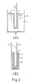
- Fig. 1(A) is a sectional view illustrating a solid electrolytic capacitor according to the present invention
- Fig. 1(B) is an enlarged sectional view illustrating the interface of a dielectric oxidation layer and a polymer layer of a heterocyclic compound.
- the solid electrolytic capacitor of the illustrated embodiment includes an aluminium plate 11 serving as a substrate of a capacitor element and capable of having a dielectric oxidation layer formed thereon, an aluminium oxide (Al2O3) layer 12 formed as a dielectric oxidation on the surface of the aluminium plate 11, a layer 13 of a polymer of the heterocylic compound pyrrole (polypyrrole) of formula: formed on the surface of the aluminium oxide layer 12, a graphite layer 15 formed as a conductive layer for terminal extraction on the polypyrrole layer 13, and a silver paste layer 16 formed on the graphite layer 15.
- Al2O3 aluminium oxide
- polypyrrole polypyrrole
- Electrode terminals 17, 18 are attached to the silver paste layer 16 and aluminum plate 11, respectively, thereby forming a capacitor element.
- An overcoat layer 19 consisting of, e.g. a polybutadiene resin is formed on the top surface of the silver paste layer 16.
- the polypyrrole layer 13 formed on the aluminum oxide layer 12 is formed by electrolytic oxidation polymerization.
- the aluminum oxide layer 12 deteriorates at several places due to the current that flows when polymerization is carried out, whereby defects 14 are produced in the aluminum oxide layer 12, as shown in (B) of Fig. 1.
- the defects 14 in the aluminum oxide layer 12 cause an increase in leakage current LC, a variance from one product to another, and a decline in yield due to a deterioration in insulation.
- these problems are solved by insulating the vicinity 13a of the defect interface of the polypyrrole layer 13 which has grown to the interface of the defect 14 of the aluminum oxide layer 12.
- the leakage current LC can be markedly reduced without bringing about an increase in dielectric loss, a variance from one product to another can be minimized and a decline in yield caused by a deterioration in insulation can be greatly reduced.
- a grealy improved capacitor can be obtained.
- the surface of the aluminum plate 11 is roughened by an etching treatment, then the aluminum oxide (Al2O3) layer 12 is formed by a well-known formation process on the roughened surface of the aluminum plate 11.
- the aluminum oxide layer 12 is formed by using the aluminum plate 11 as an anode and applying a predetermined formation voltage (10 V - 50 V) thereto in e.g. an adipic acid-type solution.
- the polypyrrole layer 13 is formed by preparing an electrolyte solution L which includes pyrrole and ammonium borodisalicylate (ABS) and which contains acetonitrile or acetone as the solvent, pouring the electrolyte solution L into a stainless steel vessel 10, dipping the aluminum plate 11 having the aluminum oxide layer 12 formed on its surface into the electrolyte solution L, and supplying a predetermined direct current using the stainless steel vessel 10 as a cathode and the aluminum plate 11 as an anode.
- electrolytic oxidation polymerization takes place in the electrolyte solution so that a polypyrrole layer having the chemical structure shown above is formed on the aluminum oxide layer 12.
- the thickness of the polypyrrole layer is 20 - 50 ⁇ m.
- the polymer of pyrrole that is to say the polypyrrole layer formed by electrolytic oxidation polymerization on the dielectric oxidation layer (such as the aluminum oxide layer 12) is a polymer in which the N-H radical of the pyrrole molecules and ammonium borodisalicylate (ABS) supporting electrolyte are hydrogen bonded as shown by the broken bond in the formula above
- the electrolytic oxidation polymerization should be carried out in an electrolyte solution which includes pyrrole and the supporting electrolyte in order to form the pyrrole.
- Use should be made of a supporting electrolyte containing boric acid and any one of the following ingredients:
- the aluminum plate 11 having the polymer layer 13 thereon is dipped into a graphite solution, after which the graphite on the layer 13 is allowed to harden to form the graphite layer 15.
- the resulting structure is then dipped into a silver paste solution to coat the graphite layer 15 with the silver paste. This is then allowed to harden to form the silver paste layer 16.
- a characterizing feature of the present embodiment is to insulate the region 13a of the polypyrrole layer 13 near the defect interface where the region has grown into the interface of the defect 14.
- the region 13a of the polypyrrole layer 13 near the defect is extremely small. Therefore, even if the region 13a is insulated, the leakage current LC can be markely reduced without increasing the dielectric loss (tan ⁇ ) of the capacitor, as is indicated by experimental results described later.
- the solid electrolytic capacitor element having the cross sectional structure shown in (A) of Fig. 1 is dipped in pure water (for 4 hr at a water temperature of about 80°C in the present example) to impregnate the aluminum oxide layer 12 through the polybutadiene resin undercoat layer 19, the silver paste layer 16, the graphite layer 15 and the pyrrole polymer layer 13. Since the undercoat layer 19, silver paste layer 16 and graphite layer 15 are comparatively water-permeable, the water passes through these layers and reaches the aluminum oxide layer 12.
- the solid electrolytic capacitor element is extracted from the water and aging is performed at room temperature by applying a voltage which is 1.2 to 2.0 times higher than the rated voltage of the capacitor using the terminal 18 as an anode and the terminal 17 as a cathode, by way of example.
- Fig. 3(A) is a view illustrating the distribution of leakage current LC of the solid electrolytic capacitor before the above-described aging treatment
- Fig. 3(B) is a view illustrating the distribution of leakage current LC of the solid electrolytic capacitor after the above-described aging treatment.
- the leakage current LC of the capacitor element before aging centers on 100 ⁇ A or more.
- the leakage current LC centers on about 0.01 ⁇ A.
- the aging treatment causes an oxidation reaction or a reaction accompanied by an exchange of protons between the polypyrrole molecules of the polypyrrole layer 13 and the water (H2O) molecules permeating the interior of the capacitor element and adsorbed thereon, and that as a result of this reaction, a portion of the pyrrole polymer layer 13, especially the polypyrrole 13a which has grown in the defect 14 of the aluminum oxide layer 12, changes from a semiconductor to an insulator.
- the end of the polypyrrole layer region 13a which has grown into the interface of the defect 14 of aluminum oxide layer 12 defines an acute angle. It is believed that current collects in this region and causes the generation of heat, as a result of which the aforementioned reaction readily occurs.
- the water content permeating the capacitor element is removed.
- the element is subjected to a drying treatment while the rated voltage is applied thereto in a high-temperature atmosphere (about 120°C). This completes the fabrication of the solid electrolytic capacitor element. If necessary, a resin molded cladding can be applied to the undercoat layer 19 to complete the fabrication of the solid electrolytic capacitor of the invention.
- Fig. 4 is a view showing leakage current - voltage characteristics before and after the aforementioned aging treatment.
- Voltage ratio namely the ratio (%) of applied voltage to rated voltage
- the leakage current LC ( ⁇ A) is plotted along the vertical axis.
- Curve A indicates the change in leakage current after the aging treatment
- curve B indicates the change in leakage current before the aging treatment.
- the positive (+) side is for a case where voltage is applied using the terminal 18 as the anode and the terminal 17 as the cathode.
- the negative side is for a case where voltage is applied using the terminal 17 as the anode and the terminal 18 as the cathode.
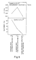
- Fig. 5 is a view showing the results of experiments regarding leakage current and dielectric loss for a solid electrolytic capacitor C perfected by the aforementioned aging treatment according to the invention, a conventional tantalum solid electrolytic capacitor A and a conventional aluminum solid electrolytic capacitor B.
- Fig. 5 illustrates the experimental results regarding leakage current LC.
- the results are based on experimental capacitors having a rated voltage of 6.3 V and a capacitance of 4.7 ⁇ F. It is shown that the solid electrolytic capacitor C of the invention has a leakage current of about 0.01 ⁇ A, which is very low in comparison with the conventional tantalum solid electrolytic capacitor A (0.02 ⁇ A) and conventional aluminum solid electrolytic capacitor B (0.42 ⁇ A).
- Fig. 5 illustrates the experimental results regarding dielectric loss (tan ⁇ ) at 10 KHz.
- the results are based on experimental capacitors having the aforementioned rated voltage of 6.3 V and a capacitance of 4.7 ⁇ F. It is shown that the solid electrolytic capacitor C of the invention has a dielectric loss (tan ⁇ ) of about 3%, which is very low in comparison with the conventional tantalum solid electrolytic capacitor A (about 52%) and conventional aluminum solid electrolytic capacitor B (about 21%).
- the solid electrolytic capacitor of the present invention has a low leakage current and little dielectric loss (tan ⁇ ) and exhibits excellent capacitor characteristics in comparison with the conventional solid electrolytic capacitors.
- the resin undercoat layer 19 is applied to the capacitor element.
- the purpose of this layer is to prevent the moisture impregnating the capacitor element from vanishing during the aging treatment.
- the means for preventing this loss of the moisture impregnating the element is not limited to the undercoat layer 19.
- any means will suffice so long as the the capacitor element can maintain the adsorbed water or at least the solution containing the water during the ageing treatment.
- a method whereby the capacitor element is immersed in a constant temperature and constant humidity tank kept at 40°C and 90 to 95% of humidity and voltage for ageing is applied is effective to insulate the defect of the polymer layer.
- An effective method of insulating the region 13a of the polypyrrole layer 13 near the defect interface of the aluminum oxide layer 12 entails subjecting the capacitor element to permeation and absorption of water or a solution containing at least water and applying a predetermined DC voltage or AC voltage across the terminals 17, 18.
- a predetermined DC voltage or AC voltage across the terminals 17, 18.
- metal plate constituting the body of the capacitor element.
- the metal is capable of having the dielectric oxidation layer formed thereon, a plate of tantalum, niobium or titanium can be used.
- the metal body can be formed by sintering.
- a polymer of furan or thiophene in place of a polymer of pyrrole a polymer of furan or thiophene can be used.
- Polymer layers of these heterocylic compounds can be formed on the dielectric oxidation layer by electrolytic oxidation polymerization in a solution containing these heterocylic compounds, if the electrolyte solution in which the heterocylic compound is dissolved is held at the aforementioned low temperatures and electrolytic oxidation polymerization is carried out in the electrolyte solution; the polymer layers of these heterocyclic compounds near the defect interface of the aluminum oxide layer can also be changed from a semiconductor to an insulator.
- the conductive layer is formed over the entire surface of the polymer layer.
- the purpose of the conductive layer is to electrolytically connect the inner end of the terminal to the polymeric layer, it is not always necessary to form the conductive layer on the entire surface of the polymer layer.
- the conductive layer may be formed in a portion only of the polymer layer surface having regard to the production cost, structure, and electrical characteristics.
- the conductive layer consists of two layers, namely the graphite layer 15 and silver paste layer 6.
- the conductive layer structure is not limited thus, but may be of single or multiple layers.
- the conductive material used is not specifically limited to the above-mentioned material as long as an electrically conductive layer is formed.
- terminals having various shapes and structure such as a wire or a lug, may be used to suit the capacitor application.
- the metal plate 11 or the conductive layer itself may be used as the terminal.
- the polymer layer of the heterocyclic compound near the defect interface of the dielectric oxidation layer is converted into an insulator, thereby providing a solid electrolytic capacitor using a layer of a polymer of a heterocyclic compound as an electrolyte which, in comparison with the conventional solid electrolytic capacitor using a polymer layer of a heterocyclic compound, has a markedly reduced capacitor leakage current without an increased equivalent series resistance (ESR), namely without an increased capacitor dielectric loss (tan ⁇ ).
- ESR equivalent series resistance
- Fig. 6 is a view illustrating a process for forming the polymer layer of the heterocyclic compound.
- the apparatus includes an electrolytic bath 22 accommodating the electrolyte solution L.
- the electrolyte solution L is prepared by dissolving 0.05 mol (3.0 g) pyrrole and, as the supporting electrolyte, about 0.02 mol (6.0 g) ammonium borodisalicylate (ABS) in 1 l acetonitrile or acetone as the solvent.
- a pair of stainless steel plates 23, 23 are immersed in the electrolyte solution L inside the electrolytic bath 22, as well as an aluminum substrate 21 interposed between the stainless steel plates 23, 23.
- the aluminum substrate 21 is obtained by forming an aluminum oxide layer on an aluminum plate.
- the anode of a DC power supply 24 is connected directly to the aluminum substrate 21, and the cathode of the DC power supply 24 is connected to both of the stainless steel plates 23, 23.
- the electrolyte solution L in the electrolytic bath 22 is held at a low temperature (e.g. -40°C). Under these conditions, a current of a predetermined value (e.g. about 10 mA/cm2) is passed continuously across the aluminum substrate 21 and each of the stainless steel plates 23, 23 for 10 min to give rise to electrolytic oxidation polymerization, thereby forming the polypyrrole layer on the aluminum oxide of the aluminum substrate 21.
- a current of a predetermined value e.g. about 10 mA/cm2
- the surface of the aluminum substrate 21 coated with the polypyrrole layer is washed with pure water.
- the polypyrrole layer could be formed on the surface of the anodic aluminum substrate 21 in good order by maintaining the electrolyte solution at a low temperature.
- the reason for this is surmised to be that the molecular motion of the monomer and oligomer on the anode surface is slowed down so that they stop near the surface of the anode without being diffused into the solution, as a result of which the formation of the polypyrrole layer takes place satisfactorily.
- the reaction of the aluminum is suppressed by the low temperature.
- Fig. 8 is a view showing the relationship between the electrolyte solution temperature and polypyrrole layer formation.
- the capacitance of a capacitor having a prescribed rated capacitance, after the polypyrrole layer formation, is formed is plotted on the vertical axis with the rated capacitance as 100, and the electrolyte solution temperature is plotted along the horizontal axis.
- the electrolyte solution components are acetonitrile as the solvent, 0.4 wt.% ammonium borodisalicylate as the supporting electrolyte and 0.5 wt.% pyrrole.
- the time taken for electrolytic oxidation polymerization is approx imately 10 minutes.
Landscapes
- Engineering & Computer Science (AREA)
- Power Engineering (AREA)
- Microelectronics & Electronic Packaging (AREA)
- Chemical & Material Sciences (AREA)
- Chemical Kinetics & Catalysis (AREA)
- Electrochemistry (AREA)
- Manufacturing & Machinery (AREA)
- Polyoxymethylene Polymers And Polymers With Carbon-To-Carbon Bonds (AREA)
Applications Claiming Priority (2)
| Application Number | Priority Date | Filing Date | Title |
|---|---|---|---|
| JP8658487 | 1987-04-07 | ||
| JP86584/87 | 1987-04-07 |
Publications (2)
| Publication Number | Publication Date |
|---|---|
| EP0285728A1 true EP0285728A1 (fr) | 1988-10-12 |
| EP0285728B1 EP0285728B1 (fr) | 1992-06-24 |
Family
ID=13891058
Family Applications (1)
| Application Number | Title | Priority Date | Filing Date |
|---|---|---|---|
| EP87311473A Expired - Lifetime EP0285728B1 (fr) | 1987-04-07 | 1987-12-24 | Condensateur électrolytique solide et son procédé de fabrication |
Country Status (3)
| Country | Link |
|---|---|
| EP (1) | EP0285728B1 (fr) |
| KR (1) | KR910005752B1 (fr) |
| DE (1) | DE3780031T2 (fr) |
Cited By (4)
| Publication number | Priority date | Publication date | Assignee | Title |
|---|---|---|---|---|
| EP0408913A1 (fr) * | 1989-06-20 | 1991-01-23 | Sanyo Electric Co., Ltd. | Procédé d'application d'un film conducteur à un substrat formé d'un corps conducteur revêtu d'un film isolant |
| DE4029110A1 (de) * | 1989-10-02 | 1991-04-11 | Roederstein Kondensatoren | Verfahren zur herstellung von kondensatoren sowie nach diesem verfahren hergestellte kondensatoren |
| US5189770A (en) * | 1990-08-13 | 1993-03-02 | Siemens Aktiengesellschaft | Method of making solid electrolyte capacitor |
| US5586000A (en) * | 1993-12-28 | 1996-12-17 | Nec Corporation | Solid electrolytic capacitor and process for production thereof |
Families Citing this family (1)
| Publication number | Priority date | Publication date | Assignee | Title |
|---|---|---|---|---|
| JP3974645B2 (ja) | 2005-03-30 | 2007-09-12 | 昭和電工株式会社 | 固体電解コンデンサ素子、その製造方法、及び固体電解コンデンサ |
Citations (3)
| Publication number | Priority date | Publication date | Assignee | Title |
|---|---|---|---|---|
| FR1221171A (fr) * | 1958-04-02 | 1960-05-31 | Western Electric Co | Perfectionnements aux condensateurs électrolytiques secs |
| FR1290087A (fr) * | 1961-05-30 | 1962-04-06 | Hiradastechnikai Ipari Ki | Condensateur à électrolyte sec et son procédé d'obtention |
| EP0264786A2 (fr) * | 1986-10-23 | 1988-04-27 | BASF Aktiengesellschaft | Condensateur à l'état solide comprenant un polymère électroconducteur comme élément de l'électrolyte solide |
-
1987
- 1987-12-01 KR KR1019870013634A patent/KR910005752B1/ko not_active Expired
- 1987-12-24 DE DE8787311473T patent/DE3780031T2/de not_active Expired - Fee Related
- 1987-12-24 EP EP87311473A patent/EP0285728B1/fr not_active Expired - Lifetime
Patent Citations (3)
| Publication number | Priority date | Publication date | Assignee | Title |
|---|---|---|---|---|
| FR1221171A (fr) * | 1958-04-02 | 1960-05-31 | Western Electric Co | Perfectionnements aux condensateurs électrolytiques secs |
| FR1290087A (fr) * | 1961-05-30 | 1962-04-06 | Hiradastechnikai Ipari Ki | Condensateur à électrolyte sec et son procédé d'obtention |
| EP0264786A2 (fr) * | 1986-10-23 | 1988-04-27 | BASF Aktiengesellschaft | Condensateur à l'état solide comprenant un polymère électroconducteur comme élément de l'électrolyte solide |
Cited By (4)
| Publication number | Priority date | Publication date | Assignee | Title |
|---|---|---|---|---|
| EP0408913A1 (fr) * | 1989-06-20 | 1991-01-23 | Sanyo Electric Co., Ltd. | Procédé d'application d'un film conducteur à un substrat formé d'un corps conducteur revêtu d'un film isolant |
| DE4029110A1 (de) * | 1989-10-02 | 1991-04-11 | Roederstein Kondensatoren | Verfahren zur herstellung von kondensatoren sowie nach diesem verfahren hergestellte kondensatoren |
| US5189770A (en) * | 1990-08-13 | 1993-03-02 | Siemens Aktiengesellschaft | Method of making solid electrolyte capacitor |
| US5586000A (en) * | 1993-12-28 | 1996-12-17 | Nec Corporation | Solid electrolytic capacitor and process for production thereof |
Also Published As
| Publication number | Publication date |
|---|---|
| DE3780031D1 (de) | 1992-07-30 |
| DE3780031T2 (de) | 1993-01-14 |
| KR910005752B1 (ko) | 1991-08-02 |
| KR880013199A (ko) | 1988-11-30 |
| EP0285728B1 (fr) | 1992-06-24 |
Similar Documents
| Publication | Publication Date | Title |
|---|---|---|
| US4785380A (en) | Solid electrolytic capacitor, and method of manufacturing same | |
| US4943892A (en) | Solid electrolytic capacitor and method for manufacturing the same | |
| US4934033A (en) | Method of manufacturing a solid electrolytic capacitor | |
| EP0637043B1 (fr) | Condensateur à électrolyte solide et son procédé de fabrication | |
| EP0617442B1 (fr) | Condensateur à électrolyte solide et sa méthode de fabrication | |
| EP0416926A2 (fr) | Procédé de fabrication d'un condensateur à electrolyte solide | |
| US5117332A (en) | Solid electrolytic capacitors and method for manufacturing the same | |
| EP1876612B1 (fr) | Élément de condensateur à électrolyte solide, son procédé de fabrication, et condensateur à électrolyte solide | |
| US5223120A (en) | Method for fabricating solid electrolytic capacitors using an organic conductive layer | |
| EP0213631B1 (fr) | Condensateur à électrolyte solide et son procédé de préparation | |
| EP0285728B1 (fr) | Condensateur électrolytique solide et son procédé de fabrication | |
| JP3339511B2 (ja) | 固体電解コンデンサの製造方法 | |
| JP3488260B2 (ja) | 固体電解コンデンサの製造方法 | |
| JPH05304055A (ja) | 固体電解コンデンサの製造方法 | |
| JPH0563009B2 (fr) | ||
| JPH0318009A (ja) | タンタル固体電解コンデンサの製造方法 | |
| EP0803885B1 (fr) | Procédé de fabrication d'un condensateur à électrolyte solide | |
| JP2617734B2 (ja) | 固体電解コンデンサの製造方法 | |
| JPH11191518A (ja) | 有機固体電解コンデンサ及びその製造方法 | |
| KR940005995B1 (ko) | 고체전해 콘덴서 | |
| JPH0365007B2 (fr) | ||
| JPH0393214A (ja) | 固体電解コンデンサの製造方法 | |
| JP3332238B2 (ja) | 固体電解コンデンサの製造方法 | |
| KR0154126B1 (ko) | 고체 전해 콘덴서 및 그의 제조방법 | |
| JPH02219211A (ja) | 固体電解コンデンサの製造方法 |
Legal Events
| Date | Code | Title | Description |
|---|---|---|---|
| PUAI | Public reference made under article 153(3) epc to a published international application that has entered the european phase |
Free format text: ORIGINAL CODE: 0009012 |
|
| AK | Designated contracting states |
Kind code of ref document: A1 Designated state(s): DE FR GB NL |
|
| 17P | Request for examination filed |
Effective date: 19890325 |
|
| 17Q | First examination report despatched |
Effective date: 19910806 |
|
| GRAA | (expected) grant |
Free format text: ORIGINAL CODE: 0009210 |
|
| AK | Designated contracting states |
Kind code of ref document: B1 Designated state(s): DE FR GB NL |
|
| REF | Corresponds to: |
Ref document number: 3780031 Country of ref document: DE Date of ref document: 19920730 |
|
| ET | Fr: translation filed | ||
| PLBE | No opposition filed within time limit |
Free format text: ORIGINAL CODE: 0009261 |
|
| STAA | Information on the status of an ep patent application or granted ep patent |
Free format text: STATUS: NO OPPOSITION FILED WITHIN TIME LIMIT |
|
| 26N | No opposition filed | ||
| PGFP | Annual fee paid to national office [announced via postgrant information from national office to epo] |
Ref country code: GB Payment date: 19971212 Year of fee payment: 11 |
|
| PGFP | Annual fee paid to national office [announced via postgrant information from national office to epo] |
Ref country code: DE Payment date: 19971222 Year of fee payment: 11 |
|
| PGFP | Annual fee paid to national office [announced via postgrant information from national office to epo] |
Ref country code: FR Payment date: 19971229 Year of fee payment: 11 |
|
| PGFP | Annual fee paid to national office [announced via postgrant information from national office to epo] |
Ref country code: NL Payment date: 19971231 Year of fee payment: 11 |
|
| PG25 | Lapsed in a contracting state [announced via postgrant information from national office to epo] |
Ref country code: GB Free format text: LAPSE BECAUSE OF NON-PAYMENT OF DUE FEES Effective date: 19981224 |
|
| PG25 | Lapsed in a contracting state [announced via postgrant information from national office to epo] |
Ref country code: NL Free format text: LAPSE BECAUSE OF NON-PAYMENT OF DUE FEES Effective date: 19990701 |
|
| GBPC | Gb: european patent ceased through non-payment of renewal fee |
Effective date: 19981224 |
|
| PG25 | Lapsed in a contracting state [announced via postgrant information from national office to epo] |
Ref country code: FR Free format text: LAPSE BECAUSE OF NON-PAYMENT OF DUE FEES Effective date: 19990831 |
|
| NLV4 | Nl: lapsed or anulled due to non-payment of the annual fee |
Effective date: 19990701 |
|
| REG | Reference to a national code |
Ref country code: FR Ref legal event code: ST |
|
| PG25 | Lapsed in a contracting state [announced via postgrant information from national office to epo] |
Ref country code: DE Free format text: LAPSE BECAUSE OF NON-PAYMENT OF DUE FEES Effective date: 19991001 |