EP0286483B1 - Verfahren und Einrichtung zur Bewegungsabschätzung in einer sich bewegenden Bildfolge - Google Patents
Verfahren und Einrichtung zur Bewegungsabschätzung in einer sich bewegenden Bildfolge Download PDFInfo
- Publication number
- EP0286483B1 EP0286483B1 EP88400649A EP88400649A EP0286483B1 EP 0286483 B1 EP0286483 B1 EP 0286483B1 EP 88400649 A EP88400649 A EP 88400649A EP 88400649 A EP88400649 A EP 88400649A EP 0286483 B1 EP0286483 B1 EP 0286483B1
- Authority
- EP
- European Patent Office
- Prior art keywords
- displacement
- image
- gradient
- calculation
- calculating
- Prior art date
- Legal status (The legal status is an assumption and is not a legal conclusion. Google has not performed a legal analysis and makes no representation as to the accuracy of the status listed.)
- Expired - Lifetime
Links
Images





Classifications
-
- H—ELECTRICITY
- H04—ELECTRIC COMMUNICATION TECHNIQUE
- H04N—PICTORIAL COMMUNICATION, e.g. TELEVISION
- H04N7/00—Television systems
- H04N7/01—Conversion of standards, e.g. involving analogue television standards or digital television standards processed at pixel level
- H04N7/0135—Conversion of standards, e.g. involving analogue television standards or digital television standards processed at pixel level involving interpolation processes
- H04N7/014—Conversion of standards, e.g. involving analogue television standards or digital television standards processed at pixel level involving interpolation processes involving the use of motion vectors
-
- G—PHYSICS
- G06—COMPUTING OR CALCULATING; COUNTING
- G06T—IMAGE DATA PROCESSING OR GENERATION, IN GENERAL
- G06T7/00—Image analysis
- G06T7/20—Analysis of motion
- G06T7/269—Analysis of motion using gradient-based methods
-
- H—ELECTRICITY
- H04—ELECTRIC COMMUNICATION TECHNIQUE
- H04N—PICTORIAL COMMUNICATION, e.g. TELEVISION
- H04N19/00—Methods or arrangements for coding, decoding, compressing or decompressing digital video signals
- H04N19/50—Methods or arrangements for coding, decoding, compressing or decompressing digital video signals using predictive coding
- H04N19/503—Methods or arrangements for coding, decoding, compressing or decompressing digital video signals using predictive coding involving temporal prediction
-
- H—ELECTRICITY
- H04—ELECTRIC COMMUNICATION TECHNIQUE
- H04N—PICTORIAL COMMUNICATION, e.g. TELEVISION
- H04N19/00—Methods or arrangements for coding, decoding, compressing or decompressing digital video signals
- H04N19/50—Methods or arrangements for coding, decoding, compressing or decompressing digital video signals using predictive coding
- H04N19/503—Methods or arrangements for coding, decoding, compressing or decompressing digital video signals using predictive coding involving temporal prediction
- H04N19/51—Motion estimation or motion compensation
Definitions
- the invention relates to a method and a device for estimating motion in a sequence of moving images.
- the displacement estimated at the homologous point in the previous image is still used but this supposes, as previously, a slight temporal variation of the movement and requires the use of a displacement image memory.
- the object of the invention is to overcome the aforementioned drawbacks.
- the subject of the invention is a method of estimating movement in a sequence of animated images of the television type where each image is formed by a determined number of light points arranged at the intersections of rows and columns, of the type in which the motion estimation is obtained by the execution of a gradient algorithm which minimizes the quadratic deviation of the local variations in luminance of the current point of the image with the point which is homologous to it in the previous image characterized in that it consists in initializing the execution of the algorithm by values of displacements estimated according to several directions within the close causal vicinity of the current point and in propagating each estimate in the direction of the scanning of the lines of l 'picture.
- the method according to the invention consists in determining a field of movement between two successive frames of a sequence of images in the form of a vector field assigned to a fictitious image frame located nearby. of the two frames.
- the invention also relates to a device for implementing the above method.
- the invention has the main advantage that it makes it possible to avoid having to detect the moving contours and to estimate their movement by matching with the contours of the image. previous by resetting the displacement algorithm at these contours.
- the method and the device according to the invention also have the advantage that they make it possible to reconstruct the luminance values of the pixels of a missing frame in a series of images having the same scene.
- each pixel is provided with a motion vector and is interpolated from the known frames framing it in the direction of the associated motion vector, the reconstruction of the pixels of a missing frame is automatically adapted to the motion.
- the advantage of such an interpolation is that it makes it possible to convert a series of video images of frame frequency defined in one standard to another standard. It allows, for example, the transition from a standard where the frame frequency is 50 Hz to another standard where the frame frequency is 60 Hz. In this case, like the instants of shooting at the frequency of 60 Hz and at the frequency of 50 Hz do not coincide, the method according to the invention advantageously allows the interpolation of the missing frames from the available frames.
- the method according to the invention which is described below is based on the use of a displacement estimation algorithm of the type described in an article in the publication BELL SYSTEM TECHNOLOGIE volume 58 pages 631 to 670 of MARS 1979 Part. entitled "Motion compensated television coding" and for author A.N NETRAVALI and JD. ROBBINS.
- the gradient algorithm which is developed there minimizes the quadratic deviation of the local variations in luminance of each current point of a television image between the current point and the point which is homologous to it in the previous image.
- espsilon is defined by the relation: or with the condition that if:
- the relation (3) shows that the larger the gradient becomes, the more the corrective term for the displacement estimated in the previous iteration decreases.
- the method according to the invention uses the existing inter-image differences between two successive images IMS t-1 and IMS t in a sequence of images, IMS t designating the image at time t and IMS t- 1 the previous image, the time unit considered being the image period.
- the process takes place according to several stages which are represented diagrammatically on the flowchart of figure 1. According to a first stage represented in 1 in figure 1, each current IMS image is analyzed point to point by scanning each line.
- the estimated displacement is limited in the image in rows and columns within a rectangle of coordinates ⁇ DX MAX and ⁇ DY MAX relative to the current point.
- the motion estimation area in the current image is limited to by DX MAX and DY MAX ( Figure 2).
- the search for the displaced point is done throughout the previous image.
- the image is composed of two interlaced frames, a frame 1 and a frame 2.
- frame 1 is taken at time t and frame 2 at time , T representing the image period.
- the estimation of the movement takes place according to an inter-image mode, that is to say by comparing the frames 1 and the frames 2 of two successive images. If m denotes the number of lines included in an image, the lines of frame 1 are numbered from 1 to 2 and those of frame 2 are numbered from m 2 + 1 to m.
- FIG. 2 A representation of the corresponding estimation zones is shown in FIG. 2 in the form of a rectangle for each of the frames 1 and 2 respectively of the current image IMS (t) and of the previous image IMS (tT).
- DC and FC respectively designate the first and the last useful column of the image
- DL 1 and FL 1 respectively designate the first and the last useful line of the frame n ° 1 and DL 2 and FL 2 respectively designate the first and the last useful line of frame n ° 2.
- the displacements which are estimated in the closest causal neighborhood of the current point are used to initialize the motion estimation algorithm.
- This causal neighborhood contains four displacements which are used to initialize four estimates of motion in parallel.
- the propagation of the estimate follows in the process the normal scanning of television images. However, to avoid favoring a direction of propagation in the image from left to right for example, the scanning direction is reversed every other line alternately.
- a representation of this scanning in alternating even and odd lines is represented in FIG. 3A and the initial values D6, , and Dg for the odd and even lines are shown respectively in FIGS. 3B and 3C.
- the threshold Sg is the threshold used on the modulus of the current gradient.
- the unit of displacement in X is formed by the interval separating two points on the same line and the unit of displacement in Y is formed by the interval separating two lines in the same frame.
- the gradients are calculated according to the known method described in the article IEEE Trans. on Com., vol. com.32, n ° 8 of August 1984 having for title "Movement compensated inter-frame prediction for NTSC color TV signals" and having for author S. SABRI.
- Figure 5 represents displacements in the previous IMS image (t-1).
- the luminance I B of the current point displaced in the previous image is obtained by bilinear interpolation of the luminances I n of the neighboring points, which is expressed with the notations of FIG. 5 by the relation
- the horizontal gradient is:
- the vertical gradient is:
- the search area in the IMS frame (t-1) for a current point P (z, t) is defined in a rectangle of dimension 30 ⁇ 10 as shown in FIG. 6.
- the four displacement estimates are carried out in parallel from the 4 initial values , and D D 0 .
- the decision criterion then consists in choosing the displacement which among the values and D D 0 gives the lowest absolute value of displaced inter-image difference DFD (z, D o ).
- the choice is made in order D , D , D and D (steps 9 to 13 of figure 7).
- the displacement takes the value 0 (step 17).
- the displacement chosen is the first which gives a
- Each iteration i (0 ⁇ i ⁇ i MAX is thus associated with a displacement D i , an displaced inter-image difference DFD and a number of iteration i.
- the decision is then made on the lowest number of iterations, then on the minimum inter-image difference displaced DFD, to then possibly make an arbitrary choice.
- FIG. 8 An embodiment of a device corresponding to the method of the invention is shown in FIG. 8. It consists of a set of line memories 18, an image memory 19, a device for calculating the module of the current gradient 20 , a switching device 21 as well as by decision-making bodies 22 and 22 bis and displacement estimation 23.
- the device for calculating the module of the current gradient receives its information from all of the line memories 18 and provides the result calculations to the displacement estimation device 23 and to the routing device 21.
- the displacement estimation device also has two inputs which are connected on the one hand, to the output of all the line memories 18 and d on the other hand, at the output of the image memory 19.
- the line memory 18 serves as a buffer to the image memory 19 to store the refresh information of the image memory 19 while waiting for the points analyzed are outside the browser window.
- the calculations carried out take place at the point frequency, at the rate of clock pulses H l and H k supplied by a line clock not shown.
- the device 20 determines the number of the current line 1 and as a function of the parity of the number of the current line 1 it determines the number of the column of the current point k. Then having the coordinates (k, l) of the current point, the device 20 calculates the modulus of the current gradient.
- the switching device 21 compares the result of the calculation supplied by the device 20 with a reference threshold Sg and according to the algorithm represented in figure 1 validates its entry 1 or 2.
- Entry 1 is chosen if grad I (z, t)
- the decision-making bodies 22 and 22 bis have the functionalities described by the flowchart of FIG. 7, and can be carried out in a known manner, either using a microprogrammed structure of the microprocessor type, or again using a wired logic composed in a known manner by comparator circuits.
- the displacement estimation device which is represented in FIG. 9 is constituted by an initialization block 24 made up of registers 25 and 26 and by a calculation unit 23 formed by the elements 27 to 46.
- the latter provides the information of displacement to the decision-maker 22.
- the input 2 of of the switching device 21, FIG. 8, is connected to the decision-maker 22.
- the initialization block 24 makes it possible to initialize the algorithm for calculating displacement.
- Block 24 includes a first register 25 and a second register 26. These registers are formed of two distinct parts, one for storing binary words representing the mode of displacement in x or in y called respectively MDX and MDY and the other to serve as a buffer for the MTDX and MTDY travel modes calculated by the decision-making body 22.
- MTDX and MTDY are used as intermediaries before overwriting the words MDX and MDY corresponding to the displacements D (k-1, 1-1) for the passage to the analysis of the next point (k + 1, 1) such as shown in Figure 10A. They also serve as intermediaries before overwriting the words MDX and MDY corresponding to the displacements D (k + 1, 1-1) for the passage to the analysis of the next point (k-1, l) as shown in Figure 10B.
- the estimated displacement D (FC, I) is automatically put in the words (MTDX, MTDY) and in addition in the words of (MDX, MDY) corresponding to the displacements D (FC, I) and D (FC + 1, l).
- the device for calculating the displacement estimates composed of the elements 27 to 46, performs four displacement calculations in parallel from four initial values contained in the initialization block 24 when the spatial gradient of the current image is greater than the threshold Sg defined above.
- Information are applied respectively to the first inputs of the routing circuits 27, 32, 37 and 42, the outputs of which are connected to convergence test blocks and calculation of correction terms noted respectively (28,29), (33,34), (38.39) and (43.44).
- the results of the convergence tests and the calculation of the correction terms are applied to inputs of referral devices denoted respectively 30, 35, 40 and 45 which then direct them, ie to respective inputs of the decision-making body 22, or on devices for calculating new displacements, denoted respectively 31, 36, 41 and 46, when the resolution of the algorithm described above diverges for i less than i MAX .
- the new displacements provided by the calculation devices 31, 36, 41 and 46 are applied respectively to the second inputs of the switching devices 27, 32, 37 and 42.
- the convergence test block 28 comprises on the one hand, an interpolation circuit 47 coupled to a device 48 for calculating the absolute value of the displaced inter-image difference
- the interpolation circuit 47 possibly consisting of a programmable read only memory is also coupled to the image memory 19.
- the block for calculating the correction terms 29 comprises a device 53 for calculating the epsilon value described above coupled with a device for calculation of increment 54 and a device 55 for calculating correction values, as well as comparator circuits 56 and 57.
- the block for calculating new displacements 31 includes subtractor circuits 58 and 59 both coupled to a comparator circuit 60.
- the coupling between the convergence test block 28 and the block for calculating correction terms 29 is performed as in FIG. 9 by the switch 30.
- the input of the switch is directly coupled to the output of the computing device 52 and to the output of the computing device 48 through the switches 49 and 50.
- the initialization block 24 is coupled to the convergence test block 28 via the switch 27. This switch connects the initialization block 24 on the one hand, to a first input of the interpolation circuit 47 and on the other hand, to a first input of the computing device 51.
- the second input of the switch 27 is also coupled to the output of the calculation block of the new displacement 31 which is constituted by the comparator circuit 60.
- the operation of the displacement estimation device is as follows. For each of the current points of the image, the switch 27 transmits an initial value D o , found in the register 24, to the interpolation circuit 47 and to the gradient calculation device 51.
- the value D o initializes the estimate.
- a bilinear interpolation calculation on the value D o is performed by the interpolation circuit 47 to determine the luminance of the current point displaced in the previous image I (z-D0, t-1).
- the displaced inter-image difference DFD (Z, D0) and its absolute value are calculated by the calculating device 48 from the luminance information of the current point.
- the switch 49 transmits the value calculated by the calculation device 48 to the decision-making body 22 when the value obtained is less than or equal to the threshold S previously defined.
- are applied to the inputs of the decision-maker 22. Otherwise, the result provided by the calculation device 48 is applied to the input of the switch 50 and then to that of the decision-maker 22 when the value of l iteration i is equal to the maximum iteration value i MAX . On the other hand, when the value of the iteration i is less than the maximum value, the result is applied to the inputs of the correction calculation block 29 through the switch 30.
- the switch 30 directs the result obtained either towards the decision-making body 22 if the value of G2 obtained is less than or equal to a coefficient value equal for example to 0.125, or to the calculation block correction terms for new displacements 29 and 31.
- the value of the iteration i is increased by one unit by the increment calculating device 54 and is reset to zero on analysis of the next current point.
- the calculation of the terms (TC) x and (TC) Y of correction in X and Y is carried out by the circuit 55.
- the values (TC) x and (TC) Y obtained on the outputs of the calculation device 55 verify the relationships and
- the values (TC) x and (TC) Y obtained are applied respectively to the inputs of the comparators 56 and 57 so as to be limited, except for sign conditions, to maximum and minimum values.
- the minimum values of (TC) x and of (TC) Y are the same and fixed at 1/16, on the other hand the maximum value of (TC) x is fixed equal to 3 and the maximum value of (TC) y is fixed equal to 2.
- the terms (TC) x and (TC) y obtained are added to the displacement values of and D y 0 by circuits 58 and 59 and the results obtained D; and which correspond to the estimated displacements are again limited by the comparator circuit 60 before being applied to the second input of the switch 27.
- the switch 27 applies the estimated displacements D; and Df on circuits 47, 51, 58 or 59.
- a displacement is chosen for the current point and is written in the buffer memory 24 MTDX and MTDY. i is reset and the switch 27 returns to its starting position and the calculations described above are repeated to estimate the displacement of the new current point.
- the method and the device according to the invention described above have the drawback of being able to be implemented only for the television standards for which they were designed. Under these conditions, the luminance values of the pixels of the missing frames of a series of images representing the same scene cannot be taken into account for determining the movement of the objects of the scene.
- a variant of the method according to the invention which is described below overcomes this drawback by allowing the determination of a field of movement between two generally successive frames of a sequence of images, in the form of an assigned vector field.
- a fictitious frame generally located between two mother frames.
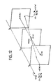
- the motion field is made up of a set of vectors. Each vector passes through a pixel of the fictitious frame and has its ends on the two parent frames which surround it.
- the mother frames are designated by their instant of shooting Ta and Tb.
- the fictitious frame is located at an instant T j intermediate between the instants Ta and Tb.
- the goal is to provide a displacement vector for each pixel of the fictitious frame considered at time T j , the luminance of each pixel being a priori unknown, from the luminance field of the frames of instants Ta and Tb.
- the instant T j can thus be located outside the interval (Ta, Tb).
- the method according to the invention is similar to the method described above with the difference, however, that it makes it possible to estimate the movement between two frames of instants Ta or Tb for the pixels of the fictitious frame Tj.
- the complexities of the algorithm and that of the resulting estimation device are of the same order.
- the motion estimate is calculated from the luminance L () of the pixels of the time frames Ta and Tb.
- the estimated motion for each pixel is in the form of a vector D with two horizontal components DX and vertical DY.
- the estimate is calculated between two frames Ta and Tb which can be of the same parity or of different parity, and for a frame Tj which can also be even or odd.
- a correcting vector, designated by dZa or dZb, is introduced into the calculation of the functions DFD and grad L. dZa depends on the relative parity of Ta and Tj, dZb depends on the relative parity of Tb and Tj.
- the method according to the invention uses the interframe differences existing between two frames of instants Ta and Tb which follow each other directly or not in a sequence of images.
- the displacement of each pixel of the fictitious frame of instant Tj is rectilinear between two frames of instants Ta and Tb, and each object element of the fictitious frame of instant Tj ( pixel luminance) is also assumed to be present in the time frames Ta and Tb.
- each point of the current frame is considered, by a scanning in lines of all the points of the frame.
- the method performs the processing indicated in step 62 to estimate four displacement values from four initial displacement values in the causal neighborhood of the current point.
- the method proceeds to the execution of step 63 and chooses a displacement from the four displacements which have been estimated in step 62.
- the method is thus proceeds by successive iterations, each end of execution of step 63 causing the initialization of the next point (step 64) and the displacements are recorded in step 65.
- the displacement between the time frames Ta and Tb is limited to values ⁇ DX max in horizontal displacement and ⁇ DY max in vertical displacement.
- the set of points on the frame Tj for which a displacement vector is estimated is included inside another rectangle whose center coincides with the center of the frame and whose dimensions are smaller than the frame dimensions of DX max + 2 columns and DY max + 2 lines (+2 is imposed by the calculation of the spatial gradient).
- a test can be added to verify that the ends of the vector are actually located on the frames of instants Ta and Tb. If this is not the case, it is easy to modify this vector so as to have for the current pixel a new vector, the closest to the old, which has its ends on the frames of instants Ta and Tb, so that we can estimate the DFD and grad L functions.
- the displacements which are estimated in the closest causal neighborhood of the current point are used to initialize the motion estimation algorithm.
- This causal neighborhood contains four displacements which are used to initialize four estimates of motion in parallel.
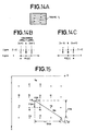
- FIG. 14A A representation of this scanning in alternating even and odd lines is represented in FIG. 14A, and the pixels A, B, C, D whose displacement vectors Dô, Dô, Dô and Dg are the initial displacement vectors of Z, for the lines odd and even, are shown in Figures 14B and 14C respectively.
- the unit of displacement in X is formed by the interval separating two points on the same line and the unit of displacement in Y is formed by the interval separating two lines of the same frame.
- the gradients are calculated as described below, and illustrated in FIG. 15 which represents a portion of the frame of time Ta, and a displacement vector whose end on the frame of time Ta has the coordinates (Z -DA, Ta) and has the luminance LA.
- the luminance LB of its end in the frame of time Tb, and the displacement vector DB at this point are calculated in the same way.
- the DA and DB vectors being collinear and such that
- the displaced interframe difference is calculated by the relation:
- Dmax being fixed, DA max and DB max depend on the distance from the frame of time Tj to the frames of times Ta and Tb.
- the search area in the time frames Ta and Tb for a current point P (Z, Tj) is then defined by a rectangle on each frame Ta and Tb of respective dimensions: and
- the four displacement estimates are carried out in parallel from the 4 initial values and Dô.
- the method gives four values of DFD (Di) which are compared to the threshold S.
- the selected displacement is the first which gives the value DFD less than or equal to the threshold S. If several displacements are obtained at the same iteration, the one which gives the lowest interframe displaced DFD difference is chosen. In the event of a new tie on the DFD value, an arbitrary choice is made in the order: , and D °.
- the decision is taken on the lowest number of iterations, then on the minimum interframe displaced DFD difference, then thereafter according to possibly an arbitrary choice.
- the device represented in FIG. 17 comprises, similar to that of FIG. 8, a set of line memories 18, a frame memory 19, a device for determining the scanning direction 20, as well as displacement estimation members. 23, decision 22 and initialization of the motion vectors 24.
- the displacement estimation device has two inputs which are connected on the one hand, to the output of the frame memory 19, on the other hand, to the output of the line memory 18.
- Each of the line memories 18 serves as a buffer for the frame memory 19 for storing the refresh information of the frame memory 19 while waiting for the points analyzed to be outside the exploration window.
- an exploration window of the type shown in FIG. 16 and occupying, for example, a space of 8 lines a line memory having a point storage capacity corresponding to 10 successive lines appears to be quite sufficient. .
- the calculations carried out take place at the point frequency, at the rate of clock pulses H1 to Hk supplied by a line clock not shown.
- the device for determining the scanning direction 20 determines the number of the current line 1 and as a function of its part it determines the number of the column of the current point k, so as to have the coordinates (k, 1) of the current point.
- the decision member 22 has the functionalities described in FIG. 18, and can be implemented in a known manner, either using a microprogrammed structure of the microprocessor type, or again using a wired logic obtained. in known manner by means of comparator circuits.
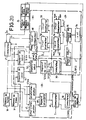
- the displacement estimation device which is represented in FIG. 18 is formed in a similar manner to that of FIG. 9 by an initialization block 24 made up of registers 25 and 26 and by a calculation unit 23 formed of the elements 27 to 46.
- the calculation unit 23 provides the displacement information , and D? to the decision-making body 22.
- the initialization block 24 initializes the displacement calculation algorithm.
- the initialization block 24 comprises a first register 25 and a second register 26. These registers are formed by two distinct parts, one representing the mode of displacement in x or in y called respectively MDX and MDY and the other to serve buffer memory to the MTDX and MTDY travel modes calculated by the decision-making body 22.
- NC designates the number of pixels for which a movement is estimated on each line.
- MTDX and MTDY are used as intermediaries before overwriting the words MDX and MDY contained in registers 25 and 26 corresponding to displacements D (k-1, 1-1) for the passage to the analysis of the next point ( k + 1, 1) as shown in Figure 19A. They also serve as intermediaries before overwriting the words MDX and MDY contained in registers 25 and 26 corresponding to the displacements (Dk + 1, 1-1) for the passage to the analysis of the next point (k-1, I ) as shown in Figure 19B.
- the four initial values are applied respectively to the first inputs of routing circuits 27, 32, 37 and 42 whose outputs are connected to blocks of test of convergence and calculation of terms of corrections noted respectively (28,29), (33, 34), (38, 39) and (43, 44).
- the results of the convergence tests and the calculation of the correction terms are applied to inputs of referral devices denoted respectively 30, 35, 40 and 45 which then direct them, ie to respective inputs of the decision-making body 22, or on devices for calculating new displacements, denoted respectively 31, 36, 41 and 46, when, the resolution of the algorithm described above diverges for i less than i max.
- the new displacements provided by the calculation devices 31, 36, 41 and 46 are applied respectively to the second inputs of the switching devices, 27, 32, 37 and 42.
- the convergence test block 28 of FIG. 20 comprises on the one hand, two interpolation circuits 47 and 47 bis, coupled to a device 48 for calculating the absolute value of the displaced interframe difference DFD, the latter being coupled to the decision member 22 through switches 49, 50; and on the other hand, two gradient calculation devices 51 and 51 bis coupled to a device 52 for calculating the displaced average gradients itself being coupled to a device 52 bis for calculating the sum of the squares of the displaced average gradients.
- the interpolation circuit 47 optionally constituted by a programmable read only memory, is also coupled to the frame memory 19.
- the interpolation circuit 47 bis, also optionally constituted by a programmable read only memory is coupled to the line memory 18.
- the correction terms calculation block 29 includes a device 53 for calculating the epsilon correction value described above, coupled to an increment calculation device 54 and to a 55 calculation device for correction values, as well as comparator circuits 56 and 57.
- the block for calculating new displacements 31 comprises subtracting circuits 58 and 59 both coupled to a comparator circuit 60.
- the coupling between the convergence test block 28 and the block for calculating the correction terms 29 is carried out as in the figure. 18 by the switch 30.
- the input of the switch is directly coupled to the output of the computing device 52 and to the output of the computing device 48 through the switches 40 and 50.
- the initialization block 24 is coupled to the convergence test block 28 via the switch 27.
- This switch connects the initialization block 24 on the one hand, to a first input of the interpolation circuits 47 and 47 bis and secondly, at a first input of the calculation devices 51 and 51 bis.
- the second input of the switch 27 is also coupled to the output of the calculation block of the new displacement 31 which is constituted by the comparator circuit 60.
- the switch 27 transmits an initial displacement value Do, found in the register 24, intended for the interpolation circuits 47 and 47 bis and the gradient calculation devices 51 and 51 bis.
- the Do value initializes the estimate.
- a bilinear interpolation calculation is performed, on the one hand, by the interpolation circuit 47 to determine the luminance L (ZD oX (Tj-Ta) / (Tb, Ta), of the current point (Z, Tj) displaced in the previous frame of instant Ta of the value Do x (Tj-Ta) / (Tb-Ta) and on the other hand, by the interpolation circuit 47 bis to determine the luminance L (Z + Do (Tb- Tj) / (Tb-Ta), Tb) of the same current point moved this time in the next frame Tb of the value Do x (Tb-Tj) / Tb-Ta).
- the displaced interframe difference DFD (Z, Do) and its absolute value are calculated by the calculation device 48.
- the switch 49 transmits the value calculated by the calculation device 48 to the decision member 22 when the value obtained is less than or equal to the threshold S previously defined.
- the displacement Do and the absolute value of the displaced interframe difference DFD (Do) are applied to the inputs of the decision member 22. Otherwise, the result provided by the calculation device 48 is applied to the input of the switch 50 then to that of the decision-making body 22, when the value of the iteration i is equal to the maximum iteration value i max. On the other hand, in the other cases when the value of the iteration i is less than the maximum value, the result provided by the calculation device 48 is applied to the inputs of the correction calculation block 29 through the switch 30.
- the relative parities of the frames of the instants Ta and Tj are taken into account in the circuits 47 and 51 and the relative parities of the frames of the instants Tb and Tj are taken into account in the circuits 47a and 51a.
- the switch 30 directs the result obtained either towards the decision-making body 22 if the value G2 obtained is less than or equal to a coefficient value equal for example to 0.125, or to the block for calculating the terms of correction of new displacements 29 and 31.
- the value of the iteration i is increased by one unit by the increment calculating device 54 and is reset to zero on analysis of the next current point.
- the calculation of the terms (TC) x and (TC) Y of correction in X and Y is carried out by the circuit 55.
- the values (TC) x and (TC) Y obtained on the outputs of the computing device 55 verify the relationships and
- the values (TC) x and (TC) Y obtained are applied respectively to the inputs of the comparators 56 and 57 so as to be limited, except for sign conditions, to maximum and minimum values.
- the minimum values of (TC) x and of (TC) Y are the same and fixed at 1/16, on the other hand the maximum value of (TC) x is fixed at 3 and the maximum value of (TC) Y is fixed equal to 2.
- the terms (TC) x and (TC) y obtained are added to the displacement values of and D y o by circuits 58 and 59 and the results obtained D; and which correspond to the estimated displacements are again limited by the comparator circuit 60 before being applied to the second input of the switch 27.
- the switch 27 applies the estimated displacements D; and circuits 47, 47 bis, 51, 51 bis, 58 and 59.
- a displacement is chosen for the current point and is written in the zones MTDX and MTDY of the buffer memory 24.
- the value of the iteration i is reset to zero, the switch 27 returns to its starting position and the calculations described above are repeated to estimate the displacement of the new current point.
Landscapes
- Engineering & Computer Science (AREA)
- Multimedia (AREA)
- Signal Processing (AREA)
- Computer Vision & Pattern Recognition (AREA)
- Physics & Mathematics (AREA)
- General Physics & Mathematics (AREA)
- Theoretical Computer Science (AREA)
- Television Systems (AREA)
- Compression Or Coding Systems Of Tv Signals (AREA)
- Image Analysis (AREA)
Claims (25)
erhalten wird, wobei: Z die räumlichen Koordinaten des laufenden Punktes P(Z,Tj) bezeichnet, für den der Verschiebungsvektor D(Z,Tj) näherungsweise berechnet wird,
Applications Claiming Priority (4)
| Application Number | Priority Date | Filing Date | Title |
|---|---|---|---|
| FR8703991A FR2613164B1 (fr) | 1987-03-23 | 1987-03-23 | Procede et dispositif d'estimation de mouvement dans une sequence d'images animees |
| FR8703991 | 1987-03-23 | ||
| FR8717289 | 1987-12-11 | ||
| FR878717289A FR2624682B2 (fr) | 1987-03-23 | 1987-12-11 | Procede et dispositif d'estimation de mouvement dans une sequence d'images animees |
Publications (2)
| Publication Number | Publication Date |
|---|---|
| EP0286483A1 EP0286483A1 (de) | 1988-10-12 |
| EP0286483B1 true EP0286483B1 (de) | 1992-05-13 |
Family
ID=26225861
Family Applications (1)
| Application Number | Title | Priority Date | Filing Date |
|---|---|---|---|
| EP88400649A Expired - Lifetime EP0286483B1 (de) | 1987-03-23 | 1988-03-18 | Verfahren und Einrichtung zur Bewegungsabschätzung in einer sich bewegenden Bildfolge |
Country Status (6)
| Country | Link |
|---|---|
| US (1) | US4853775A (de) |
| EP (1) | EP0286483B1 (de) |
| JP (1) | JP2803818B2 (de) |
| CA (1) | CA1329649C (de) |
| DE (1) | DE3870969D1 (de) |
| FR (1) | FR2624682B2 (de) |
Families Citing this family (47)
| Publication number | Priority date | Publication date | Assignee | Title |
|---|---|---|---|---|
| FR2630842B1 (fr) * | 1988-04-29 | 1994-04-08 | Labo Electronique Physique Appli | Dispositif pour interpoler des images par estimation et compensation de mouvement et systeme convertisseur de standards de television constitue a partir d'un tel dispositif |
| GB2222498A (en) * | 1988-09-05 | 1990-03-07 | Philips Electronic Associated | Picture motion measurement |
| FR2648254B2 (fr) * | 1988-09-23 | 1991-08-30 | Thomson Csf | Procede et dispositif d'estimation de mouvement dans une sequence d'images animees |
| JP2845473B2 (ja) * | 1989-02-13 | 1999-01-13 | 繁 安藤 | 動画像の運動、非運動領域検出装置 |
| US4969036A (en) * | 1989-03-31 | 1990-11-06 | Bir Bhanu | System for computing the self-motion of moving images devices |
| DE69006083T2 (de) * | 1989-04-21 | 1994-05-26 | Sony Corp | Interpolation eines Videosignals. |
| US5045929A (en) * | 1989-05-13 | 1991-09-03 | Zenith Electronics Corporation | Three dimensional luma/chroma separation and vertical detail generation |
| US5043807A (en) * | 1989-05-23 | 1991-08-27 | Zenith Electronics Corporation | Three dimensional composite video motion detection |
| EP0405842A3 (en) * | 1989-06-26 | 1993-03-03 | Matsushita Electric Industrial Co., Ltd. | Picture coding method |
| JP3113259B2 (ja) * | 1989-07-18 | 2000-11-27 | 富士写真フイルム株式会社 | ビデオカメラの露出制御方法及び装置 |
| US5072293A (en) * | 1989-08-29 | 1991-12-10 | U.S. Philips Corporation | Method of estimating motion in a picture signal |
| JPH03117991A (ja) * | 1989-09-29 | 1991-05-20 | Victor Co Of Japan Ltd | 動きベクトル符号化装置及び復号化装置 |
| JPH03256485A (ja) * | 1990-03-06 | 1991-11-15 | Victor Co Of Japan Ltd | 動きベクトル検出回路 |
| JPH048086A (ja) * | 1990-04-26 | 1992-01-13 | Canon Inc | 符号化方式 |
| JP2863818B2 (ja) * | 1990-08-31 | 1999-03-03 | 工業技術院長 | 動画像の変化点検出方法 |
| GB2252466B (en) * | 1991-02-04 | 1994-10-19 | Sony Broadcast & Communication | Television standards converters |
| FR2684258B1 (fr) * | 1991-11-27 | 1998-06-05 | Thomson Consumer Electronics | Procede d'estimation et de codage hierarchise du mouvement de sequences d'images. |
| US5475446A (en) * | 1992-03-09 | 1995-12-12 | Matsushita Electric Industrial Co., Ltd. | Picture signal motion detector employing partial decimation of pixel blocks |
| US5353061A (en) * | 1992-10-08 | 1994-10-04 | International Business Machines Corporation | System and method for frame-differencing video compression/decompression using perceptually-constant information and image analysis |
| US5526666A (en) * | 1992-10-09 | 1996-06-18 | United States Surgical Corporation | Apparatus for forming curved rectangular bodied needles |
| US5809174A (en) * | 1993-04-13 | 1998-09-15 | C-Cube Microsystems | Decompression processor for video applications |
| US5539454A (en) * | 1995-02-06 | 1996-07-23 | The United States Of America As Represented By The Administrator, National Aeronautics And Space Administration | Video event trigger and tracking system using fuzzy comparators |
| US5579050A (en) * | 1995-03-09 | 1996-11-26 | Daewoo Electronics Co., Ltd. | Apparatus for encoding a video signal using a search grid |
| CN1108061C (zh) * | 1995-03-20 | 2003-05-07 | 大宇电子株式会社 | 利用搜索网格对视频信号编码的装置 |
| DE19548451C1 (de) * | 1995-12-22 | 1997-02-20 | Siemens Ag | Verfahren zur rechnergestützten Bewegungsschätzung für Bildpunkte zeitlich aufeinander folgender Bilder einer Videosequenz |
| GB2311184A (en) * | 1996-03-13 | 1997-09-17 | Innovision Plc | Motion vector field error estimation |
| GB2311183A (en) | 1996-03-13 | 1997-09-17 | Innovision Plc | Gradient based motion estimation |
| US6037986A (en) * | 1996-07-16 | 2000-03-14 | Divicom Inc. | Video preprocessing method and apparatus with selective filtering based on motion detection |
| US8625665B2 (en) * | 1996-09-20 | 2014-01-07 | At&T Intellectual Property Ii, L.P. | Video coder providing implicit coefficient prediction and scan adaptation for image coding and intra coding of video |
| US6341144B1 (en) * | 1996-09-20 | 2002-01-22 | At&T Corp. | Video coder providing implicit coefficient prediction and scan adaptation for image coding and intra coding of video |
| JP3930935B2 (ja) * | 1997-02-28 | 2007-06-13 | 三菱電機株式会社 | 画像処理装置 |
| WO2000034920A1 (en) | 1998-12-07 | 2000-06-15 | Koninklijke Philips Electronics N.V. | Motion vector estimation |
| US6842483B1 (en) | 2000-09-11 | 2005-01-11 | The Hong Kong University Of Science And Technology | Device, method and digital video encoder for block-matching motion estimation |
| US7085434B2 (en) * | 2002-10-01 | 2006-08-01 | International Business Machines Corporation | Sprite recognition in animated sequences |
| US7519229B2 (en) | 2004-03-30 | 2009-04-14 | Apple, Inc. | Video coding system providing separate coding chains for dynamically selected small-size or full-size playback |
| JP2007074592A (ja) * | 2005-09-09 | 2007-03-22 | Sony Corp | 画像処理装置および方法、プログラム、並びに記録媒体 |
| US8582656B2 (en) | 2007-04-13 | 2013-11-12 | Apple Inc. | Method and system for video encoding and decoding |
| US8619874B2 (en) | 2007-04-13 | 2013-12-31 | Apple Inc. | Method and system for video encoding and decoding |
| DE102007051174B4 (de) | 2007-10-25 | 2011-12-08 | Trident Microsystems (Far East) Ltd. | Verfahren zur Bewegungsschätzung in der Bildverarbeitung |
| DE102007051175B4 (de) | 2007-10-25 | 2012-01-26 | Trident Microsystems (Far East) Ltd. | Verfahren zur Bewegungsschätzung in der Bildverarbeitung |
| EP2105883A1 (de) | 2008-03-18 | 2009-09-30 | Trident Microsystems (Far East) Ltd. | Verfahren zum Testen eines Bewegungsvektors |
| DE102008014790A1 (de) | 2008-03-18 | 2009-10-01 | Micronas Gmbh | Verfahren zum Testen eines Bewegungsvektors |
| US8238612B2 (en) * | 2008-05-06 | 2012-08-07 | Honeywell International Inc. | Method and apparatus for vision based motion determination |
| DE102008036279B4 (de) | 2008-08-04 | 2011-03-17 | Trident Microsystems (Far East) Ltd. | Verfahren zur Ermittlung eines Bewegungsvektor zu einem Bildblock eines Zwischenbilds |
| US8254629B1 (en) * | 2008-08-26 | 2012-08-28 | Adobe Systems Incorporated | Methods and apparatus for measuring image stability in a video |
| CN113774177B (zh) * | 2021-09-13 | 2022-08-16 | 内蒙古科技大学 | 一种高炉布料器波纹管位移次数检测方法及装置 |
| CN117251818B (zh) * | 2023-11-17 | 2024-01-26 | 上海伯镭智能科技有限公司 | 用于无人驾驶矿车安全运营的数据管理方法 |
Family Cites Families (8)
| Publication number | Priority date | Publication date | Assignee | Title |
|---|---|---|---|---|
| JPS55158784A (en) * | 1979-05-28 | 1980-12-10 | Nec Corp | Inter-frame coding device |
| US4232338A (en) * | 1979-06-08 | 1980-11-04 | Bell Telephone Laboratories, Incorporated | Method and apparatus for video signal encoding with motion compensation |
| US4496972A (en) * | 1980-05-10 | 1985-01-29 | Deutsche Forschungs-Und Versuchsanstalt Fur Luft-Und Raumfahrt E.V. | Method for the representation of video images or scenes, in particular aerial images transmitted at reduced frame rate |
| US4383272A (en) * | 1981-04-13 | 1983-05-10 | Bell Telephone Laboratories, Incorporated | Video signal interpolation using motion estimation |
| JPH07118784B2 (ja) * | 1984-10-27 | 1995-12-18 | ソニー株式会社 | テレビジヨン信号の動き検出方法 |
| DE3689796T2 (de) * | 1985-01-16 | 1994-08-04 | Mitsubishi Denki K.K., Tokio/Tokyo | Videokodierungsvorrichtung. |
| EP0193185B1 (de) * | 1985-02-28 | 1992-05-13 | Mitsubishi Denki Kabushiki Kaisha | Adaptive Zwischenbild-Vektorquantisier-Kodiereinrichtung |
| DE3523424C1 (de) * | 1985-06-29 | 1986-10-30 | Deutsche Forschungs- und Versuchsanstalt für Luft- und Raumfahrt e.V., 5000 Köln | Verfahren zur UEbertragung und Wiedergabe von Videoszenen,insbesondere Luftbildszenen,mit reduzierter Bildfolgefrequenz bei Relativbewegung der aufgenommenen Szene gegenueber dem Aufnahmesensor |
-
1987
- 1987-12-11 FR FR878717289A patent/FR2624682B2/fr not_active Expired - Lifetime
-
1988
- 1988-03-18 EP EP88400649A patent/EP0286483B1/de not_active Expired - Lifetime
- 1988-03-18 DE DE8888400649T patent/DE3870969D1/de not_active Expired - Fee Related
- 1988-03-22 US US07/171,835 patent/US4853775A/en not_active Expired - Lifetime
- 1988-03-22 CA CA000562126A patent/CA1329649C/en not_active Expired - Lifetime
- 1988-03-23 JP JP63069184A patent/JP2803818B2/ja not_active Expired - Lifetime
Also Published As
| Publication number | Publication date |
|---|---|
| CA1329649C (en) | 1994-05-17 |
| FR2624682A2 (fr) | 1989-06-16 |
| DE3870969D1 (de) | 1992-06-17 |
| JPS6413882A (en) | 1989-01-18 |
| JP2803818B2 (ja) | 1998-09-24 |
| EP0286483A1 (de) | 1988-10-12 |
| US4853775A (en) | 1989-08-01 |
| FR2624682B2 (fr) | 1990-03-30 |
Similar Documents
| Publication | Publication Date | Title |
|---|---|---|
| EP0286483B1 (de) | Verfahren und Einrichtung zur Bewegungsabschätzung in einer sich bewegenden Bildfolge | |
| EP0360698B1 (de) | Verfahren und Einrichtung zur Bewegungsabschätzung in einer sich bewegenden Bildfolge | |
| EP0368747B1 (de) | Bewegungsabschätzungsverfahren eines Zieles in einer Bilderfolge und Einrichtung zur Durchführung dieses Verfahrens | |
| US9681150B2 (en) | Optical flow determination using pyramidal block matching | |
| EP0390660B1 (de) | Verfahren und Einrichtung zur temporalen Interpolation von Bildern mit korrigierter Bewegungskompensation | |
| EP0849950A2 (de) | Bewegliche Muster für Kodierung von Videodaten | |
| EP0533888A1 (de) | Verfahren zur Pixel-Klassifizierung in einem Bild und zur temporalen Interpolation unter Verwendung diesr Klassifizierung. | |
| WO1991003797A1 (fr) | Procede et dispositif d'estimation et de codage hierarchise du mouvement de sequences d'images | |
| EP0568694B1 (de) | Verfahren zur schaetzung und hierarchischen kodierung von bewegung in bildfolgen | |
| KR20040105595A (ko) | 비디오 신호내의 움직임 보상에 부적당한 영역을 검출하는방법 및 장치 | |
| EP1413140B1 (de) | Verfahren zur bewegungsschätzung zwischen zwei bildern mit verwaltung der wendung einer masche und entsprechendes kodierungsverfahren | |
| FR2813485A1 (fr) | Procede de construction d'au moins une image interpolee entre deux images d'une sequence animee, procedes de codage et de decodage, signal et support de donnees correspondant | |
| EP0722251A1 (de) | Verfahren zur Bildinterpolation | |
| EP1603341B1 (de) | Verfahren und Anordnung für Bildinterpolierungssysteme mit Bewegungsschätzung und -kompensation | |
| EP3701492B1 (de) | Verfahren zur wiederherstellung von bildern | |
| FR2613164A1 (fr) | Procede et dispositif d'estimation de mouvement dans une sequence d'images animees | |
| FR2637100A1 (fr) | Procede et dispositif d'estimation de mouvement dans une sequence d'images animees | |
| EP1110409B1 (de) | Verfahren zur bewegungsschätzung zwischen zwei bildern | |
| US20030128879A1 (en) | Method for promoting temporal resolution of sequential images | |
| FR2648590A1 (fr) | Procede et dispositif d'estimation de mouvement dans une sequence d'images animees | |
| FR2729811A1 (fr) | Procede d'estimation de mouvement de regions dans des sequences d'images numeriques | |
| JP4743601B2 (ja) | 動画像処理装置 | |
| JP4785890B2 (ja) | 動き推定精度推定方法、動き推定精度推定装置、動き推定精度推定プログラム及びそのプログラムを記録したコンピュータ読み取り可能な記録媒体 | |
| FR2624680A1 (fr) | Procede et dispositif de reduction de la visibilite du bruit sur les images de television | |
| Xie et al. | Determining accurate and reliable motion fields for motion-compensated interpolation |
Legal Events
| Date | Code | Title | Description |
|---|---|---|---|
| PUAI | Public reference made under article 153(3) epc to a published international application that has entered the european phase |
Free format text: ORIGINAL CODE: 0009012 |
|
| AK | Designated contracting states |
Kind code of ref document: A1 Designated state(s): DE GB NL |
|
| 17P | Request for examination filed |
Effective date: 19890201 |
|
| RAP3 | Party data changed (applicant data changed or rights of an application transferred) |
Owner name: THOMSON-CSF |
|
| 17Q | First examination report despatched |
Effective date: 19901221 |
|
| GRAA | (expected) grant |
Free format text: ORIGINAL CODE: 0009210 |
|
| AK | Designated contracting states |
Kind code of ref document: B1 Designated state(s): DE GB NL |
|
| REF | Corresponds to: |
Ref document number: 3870969 Country of ref document: DE Date of ref document: 19920617 |
|
| GBT | Gb: translation of ep patent filed (gb section 77(6)(a)/1977) | ||
| PLBE | No opposition filed within time limit |
Free format text: ORIGINAL CODE: 0009261 |
|
| STAA | Information on the status of an ep patent application or granted ep patent |
Free format text: STATUS: NO OPPOSITION FILED WITHIN TIME LIMIT |
|
| 26N | No opposition filed | ||
| PGFP | Annual fee paid to national office [announced via postgrant information from national office to epo] |
Ref country code: DE Payment date: 19940223 Year of fee payment: 7 |
|
| REG | Reference to a national code |
Ref country code: GB Ref legal event code: 746 Effective date: 19940301 |
|
| PG25 | Lapsed in a contracting state [announced via postgrant information from national office to epo] |
Ref country code: DE Effective date: 19951201 |
|
| REG | Reference to a national code |
Ref country code: GB Ref legal event code: IF02 |
|
| PGFP | Annual fee paid to national office [announced via postgrant information from national office to epo] |
Ref country code: GB Payment date: 20060209 Year of fee payment: 19 |
|
| PGFP | Annual fee paid to national office [announced via postgrant information from national office to epo] |
Ref country code: NL Payment date: 20060320 Year of fee payment: 19 |
|
| GBPC | Gb: european patent ceased through non-payment of renewal fee |
Effective date: 20070318 |
|
| NLV4 | Nl: lapsed or anulled due to non-payment of the annual fee |
Effective date: 20071001 |
|
| PG25 | Lapsed in a contracting state [announced via postgrant information from national office to epo] |
Ref country code: NL Free format text: LAPSE BECAUSE OF NON-PAYMENT OF DUE FEES Effective date: 20071001 |
|
| PG25 | Lapsed in a contracting state [announced via postgrant information from national office to epo] |
Ref country code: GB Free format text: LAPSE BECAUSE OF NON-PAYMENT OF DUE FEES Effective date: 20070318 |