EP0286720A2 - Procédé de mesure des vecteurs de courant dans des écoulements de gaz - Google Patents
Procédé de mesure des vecteurs de courant dans des écoulements de gaz Download PDFInfo
- Publication number
- EP0286720A2 EP0286720A2 EP87114452A EP87114452A EP0286720A2 EP 0286720 A2 EP0286720 A2 EP 0286720A2 EP 87114452 A EP87114452 A EP 87114452A EP 87114452 A EP87114452 A EP 87114452A EP 0286720 A2 EP0286720 A2 EP 0286720A2
- Authority
- EP
- European Patent Office
- Prior art keywords
- focusing
- measurement
- optical axis
- angle
- flow
- Prior art date
- Legal status (The legal status is an assumption and is not a legal conclusion. Google has not performed a legal analysis and makes no representation as to the accuracy of the status listed.)
- Granted
Links
Images


Classifications
-
- G—PHYSICS
- G01—MEASURING; TESTING
- G01P—MEASURING LINEAR OR ANGULAR SPEED, ACCELERATION, DECELERATION, OR SHOCK; INDICATING PRESENCE, ABSENCE, OR DIRECTION, OF MOVEMENT
- G01P5/00—Measuring speed of fluids, e.g. of air stream; Measuring speed of bodies relative to fluids, e.g. of ship, of aircraft
- G01P5/18—Measuring speed of fluids, e.g. of air stream; Measuring speed of bodies relative to fluids, e.g. of ship, of aircraft by measuring the time taken to traverse a fixed distance
- G01P5/20—Measuring speed of fluids, e.g. of air stream; Measuring speed of bodies relative to fluids, e.g. of ship, of aircraft by measuring the time taken to traverse a fixed distance using particles entrained by a fluid stream
-
- G—PHYSICS
- G01—MEASURING; TESTING
- G01P—MEASURING LINEAR OR ANGULAR SPEED, ACCELERATION, DECELERATION, OR SHOCK; INDICATING PRESENCE, ABSENCE, OR DIRECTION, OF MOVEMENT
- G01P5/00—Measuring speed of fluids, e.g. of air stream; Measuring speed of bodies relative to fluids, e.g. of ship, of aircraft
- G01P5/26—Measuring speed of fluids, e.g. of air stream; Measuring speed of bodies relative to fluids, e.g. of ship, of aircraft by measuring the direct influence of the streaming fluid on the properties of a detecting optical wave
Definitions
- the invention relates to a method according to the preamble of claim 1 and an apparatus for performing the method.
- tein can be detected so that the flow vector can be detected in three-dimensional space using only two light beams.
- the focusing points which have different distances from the optical axis, are also offset from one another in the direction of the optical axis.
- a first measurement is carried out in which the focusing device of one beam is closer to the focusing point than that of the other beam and a second measurement reverses these conditions, so that the focusing point of the first beam is further away from the focusing device than that focusing point F1 and F2 focused.
- the axial extent L of the measurement volume MV is determined by the axial intensity distribution in the beams and by the beam path of the observing optics, which is optimized for the radiation centers.
- a particle that flies through the center of a focal point and is illuminated by the beam in question delivers a signal of maximum amplitude at a photodetector.
- the axial length L of the focusing point is chosen so that the same particle, when it flies through the edge region, only delivers a signal of one tenth of the maximum amplitude. Since in real currents the particles are always in size distributions (small particles provide a lower signal amplitude, but are more common than large particles), the small particles are still recognized in the axial center of the focal point, while only the much rarer large particles are recognized in the edge area.
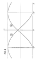
- the upper representation of FIG. 1 shows the frequency H of the detection signals of particles as a function of the axial position at which the particles cross the elongated focusing point.
- the axial length of a focal point is typically 0.4 mm.
- the centers of the focusing points F1 and F2 lie at the same distance fL (focal length) from the focusing device.
- the sensitivity characteristic is indicated by the cross-hatched areas in the beams. If the flow is at an angle to the normal to the optical axis OA of the focusing system in the plane of the rays S1 and S2 (the plane of the drawing), the frequency distributions are H a measurement can be selected two focus points that lie on a straight line that runs at a positive angle to the normal plane to the optical axis, while for the second measurement those focus points are selected that lie on a straight line that is at a negative angle to the aforementioned Normal plane runs.
- This method variant requires at least four focusing points, two of which lie on a common beam.
- the two beams can be generated by different polarization and subsequent spatial separation of light from the same light source.
- the amounts of the positive and negative angles of the straight lines passing through two pairs of focusing points are expediently the same with respect to the normal plane to the optical axis.
- FIG. 1 shows the measurement volume geometry of a two-dimensional two-focus method.
- the measuring volume MV of the flow channel two light beams S1 and S2, which run essentially parallel and at a short distance from one another, are focused at spatially separated focusing points F1 and F2.
- the axial extent L of the measurement volume MV is determined by the axial intensity distribution in the beams and by the beam path of the observing optics, which is optimized for the radiation centers.
- a particle that flies through the center of a focal point and is illuminated by the beam in question delivers a signal of maximum amplitude at a photodetector.
- the axial length L of the focusing point is chosen so that the same particle, when it flies through the edge region, only delivers a signal of one tenth of the maximum amplitude. Since in real currents the particles are always in size distributions (small particles provide a lower signal amplitude, but are more common than large particles), the small particles are still recognized in the axial center of the focal point, while only the much rarer large particles are recognized in the edge area.
- the upper representation of FIG. 1 shows the frequency H of the detection signals of particles as a function of the axial position at which the particles cross the elongated focusing point.
- the axial length of a focal point is typically 0.4 mm.
- the centers of the focusing points F1 and F2 are at the same distance fL (focal length) from the focusing device.
- the sensitivity characteristic is indicated by the cross-hatched areas in the beams. If the flow is at an angle to the normal to the optical axis OA of the focusing system in the plane of the rays S1 and S2 (the plane of the drawing), the frequency distributions are H the measured flight times t for different. Angle ⁇ shown in Fig. 3. If the angle ⁇ is not equal to zero, the effective axial length L of the measurement volume is reduced to L. This leads to a decrease in the frequency H with an increasing amount of the angle ⁇ . The influence of the flow angle ⁇ is increased by the above-mentioned axial sensitivity characteristic.
- the integral value I of the frequency distribution H is shown as a hatched area of the curves. This integral value 1 is, based on the measuring time, the measure for the measuring frequency.
- the dependence of the measuring rate on the flow angle ⁇ could be used to determine the axial component of the flow vector, but the measuring rate depends on many other parameters, such as e.g. Particle density. Laser power, sensitivity of the photodetectors u. Like. So that a clear calibration is practically not possible.
- FIG. 5 shows, in the same representation as FIG. 2, the case in which the focusing points F1 and F2 are axially offset from one another.
- the line connecting the centers of the focusing points F1 and F2 forms the angle y with the axis normal. If the angle ⁇ is changed by the focusing point F1 remaining fixed while the focusing point F2 is shifted axially parallel, the profile of the integral I shown in FIG. 6 (proportional to the measuring rate) is obtained as a function of the angle y. It can be seen that I assumes the maximum value when ⁇ is equal to ⁇ , that is to say when the straight line passing through the centers of the focusing points F1 and F2 runs exactly in the direction of flow. By determining the position of the maximum, the flow angle ⁇ can therefore be determined in relation to the normal to the optical axis of the system.
- the measurement method described assumes that the flow and measurement conditions remain unchanged during the shift of F2.
- the measuring rate then does not require any additional calibration.
- the maximum of the measuring rate will adjust to another value in a subsequent measuring cycle, the position of the maximum, i.e. the flow angle ⁇ , however, remains unchanged.
- a disadvantage is that the maximum of the curve shown in Fig. 6 runs very flat and therefore only allows an inaccurate position determination.
- the shifting of the focusing point F2 requires the acquisition of a series of measurements, which takes considerable time.
- the center of the focusing point F2 is offset by an angle y A of 45 ° from that of the focusing point F1.
- a particle which passes focus point F1 is recognized by a photodetector which generates a start signal, while a stop signal is generated when passing focus point F2 .
- FIG. 8 shows the integral I (or the measurement rate) over the angle ⁇ for both systems A and B according to FIG. 7.
- Fig. 9 is on (I B + I A) normalized difference (I B -I A) in terms of the size (I B -I A, provided (I B + I A). It can be seen that a good linearity of the curve results in. The flow angle ⁇ can thus be determined in a simple manner from the difference (I B -I A ).
- the curve can be determined by experimental calibration.
- the axial offset of the focusing points can be obtained in a simple manner by using a lens that is not completely chromatically corrected, so that different focal lengths result for different light colors.
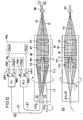
- FIG. 10 shows a device with which the two measurements A and B can be carried out in succession.
- a tubular, elongated optical head OK is provided, into which an optical fiber cable LI leads.
- the light guide cable LI is a polarization-maintaining light guide cable, the decoupling unit LI o of which is arranged along the optical axis OA.
- the diverging multicolored light beam emerging from the decoupling unit Ll o is parallel by a lens L1 lized and fed along the optical axis of the focusing device FV.
- the focusing device FV contains a dispersion prism DP and a focusing lens LS1 in the beam path. The radiation emerges from the optical head OK behind the lens LS1 in order to be focused in the measurement volume MV.
- Radiation which is reflected by particles in the measurement volume MV, is directed in parallel by the lens LS1 and the parallel radiation is guided through the dispersion prism DP in the opposite direction to the incoming radiation and fed to the converging lens LS2, which focuses this radiation onto the coupling unit LII of a light guide LII .
- the collection lens has LS2 along the optical axis OA to a central opening through which passes the emerging from the coupling-unit Ll o beam.
- the dispersion prism DP demonstrates a spatial separation of the colors present in the incident light beam. These colors are focused in the measuring volume MV at focussing points which correspond to different deflection angles and are thus offset from one another transversely to the optical axis OA. In the present case, it is assumed that the green light component is focused at the focusing point F1, while the blue light component is focused at the focusing point F2. The other light components that are focused between the focusing points F1 and F2 can be disregarded for the described method.
- FIG. 10 a shows a top view of the device and FIG. 10 b) shows a side view of the device. It can be seen that the focusing points in the measurement volume MV are arranged in a plane containing the optical axis OA, but are laterally offset from one another in this plane.
- the centers of the focusing points F1 and F2 are also offset from one another in the direction of the optical axis OA, which is achieved in that the lens LS1 has chromatic properties, ie the individual light colors are focused with different focal lengths.
- the straight line passing through the centers of the focusing points F1 and F extends in the system A of FIG. 11 at an angle ⁇ A to the normal plane of the optical axis OA.
- the flow angle to the normal plane is designated ⁇ .
- the beam plane in which the axes of the beams SB and SG run, is rotated around the optical axis A by rotating the optical head OK such that the flow vector 1 lies in this plane.
- a relatively high measurement rate is obtained in measurement A in FIG. 11, since the angle ⁇ A characterizing the axial radiation offset is approximately equal to the flow angle. which the flow vector includes with the axis normal plane.
- the particles generate start pulses when they pass the focal point F1 of the green beam SG and stop pulses when they pass the focal point F2 of the blue beam SB.
- measurement B is carried out, in which the optical head OK is rotated around the optical axis OA with respect to measurement A by 180 °.
- the blue jet SB is now at the front in the direction of flow, so that the particles passing into the focusing point F2 produce start pulses, while stop pulses are generated when passing the focusing point F1 of the green beam.
- the angle ⁇ B which the straight line running through the centers of the focusing points F1 and F2 forms with the axis normal plane, is equal to the angle -y A.
- Measurement B gives only a very low measurement rate, since in this case the angle difference ⁇ -y e is very large.
- the flow angle ⁇ is obtained from the difference of the measuring rates in measurements A and B.
- the returning light reflected by particles in the measuring volume MV is directed in parallel by the lens LS1 and the different color components become reassembled in the dispersion prism DP.
- the returning light beam is fed into the light guide Lll by the collecting lens LS2.
- This light guide leads to a further dispersion prism DP2 outside the optical head.
- the green beam SG and the blue beam SB are spatially separated from one another and both beams are fed to the light receiving device LAV, which contains a photodetector PDG for the green light and a photodetector PDB for the blue light.
- the electrical signals of the two photodetectors are fed via a switchover unit UE to the evaluation unit AE, which contains a start signal generator and a stop signal generator.
- the switchover unit UE establishes the connections shown in solid lines in FIG. 10, the output of the photodetector PDG generating the start signals, while the output of the photodetector PDB generating the stop signals.
- the switchover unit UE produces the connections shown in broken lines, the photodetector PDB generating the start signals and the photodetector PDG generating the stop signals.
- FIGS. 12 and 13 An exemplary embodiment is shown in FIGS. 12 and 13, in which measurements A and B can be carried out simultaneously.
- the optical head OK is designed in the same way as that of FIG. 10, but a polarization prism PP1 is provided instead of the dispersion prism.
- a further polarization prism PP2 is arranged between the lens LS2 and the polarization prism PP1, which has a central opening for the passage of the incoming beam.
- the light guide LI is a single-mode light guide with polarization-maintaining properties.
- the multicolored light supplied to this light guide LI is linearly polarized at 45 °.
- the polarization prism PP1 the incoming light is divided into two beams of equal intensity, polarized perpendicular to each other, which have different exit angles and are thus spatially separated from one another.
- the lens LS1 thus gives two focused beams S1 and S2 in the measurement volume MV with different directions of polarization. Since both beams are multi-colored, the individual colors of both beams are imaged on their smallest diameter at different axial locations with a suitable chromatic focal length distribution of the lens LS1. This is shown in Fig. 13.
- the green components of the two beams S1 and S2 have green focusing points FG1 and FG2 at the same axial distance from the focusing device FV and the blue focusing points FB1 and FB2 are also at the same distance from each other from the focusing device FV, but this distance is the blue focusing points from the focusing device larger than that of the green focus points from the focusing device.
- Beam S1 is polarized in parallel and beam S2 is polarized perpendicularly.
- the focus point FG1 is used to generate the start pulses and the focus point FB2 is used to generate the stop pulses.
- the straight line passing through the centers of these focusing points forms the angle y A with the normal plane to the optical axis OA.
- the focus point FB1 is used to generate the start pulses and the focus point FG2 is used to generate the stop pulses.
- the straight line passing through the centers of these two focusing points forms with the normal plane to the optical axis OA the angle ⁇ B which is -y A.
- the scattered light from the measurement volume MV is collected by the outer area of the lens LS1 and passed through the polarization beam splitter PP1. whereby the color offset and the division in the two polarization directions is reversed again.
- the further polarization beam splitter PP2 which is provided with a central opening, is used to image the differently polarized scattered light from the focusing points onto two coupling units LI11, and L112 1 that are sufficiently separated by means of the lens LS2.
- the light guides LII1 and L112 connected to the coupling units each lead to a color division unit FA1 or FA2, which spatially separates the components of interest blue and green from the multicolored light.
- the color splitting unit FA1 receives the parallel polarized light component and the color splitting unit FA2 the perpendicularly polarized light component.
- the color splitting unit FA1 generates a parallel polarized blue beam BP and a parallel polarized green beam GP. These beams are converted into electrical signals by the PDBP and PDGB photodetectors.
- the color splitting unit FA2 generates a blue beam BV and a green beam GV from the perpendicularly polarized beam, which are spatially separated from one another and are each supplied to the photodetectors PDBV and PDGV, which generate electrical pulses depending on the intensities of these light beams.
- the output signal of the photodetector PDGB is fed to the evaluation unit AE A for measurement A and generates a start pulse there, while the output signal of the photodetector PDBV generates a stop pulse in the evaluation unit AE A.
- the output signal of the photodetector PDBP is fed to the evaluation unit AE B for the second measurement B and generates a start pulse there, while the output signal of the photodetector PDBV is also fed to the evaluation unit AE B and generates a stop pulse there.
- Both measuring systems A and B register the same speed of the vector v.
- the evaluation electronics therefore only need to be carried out for one system. Only the measuring rate must be simultaneous for both systems A and B. and be determined independently of each other. This requires a relatively small additional electronic effort.
- FIG. 14 Another, even simpler variant of the method is shown in FIG. 14.
- the beam path shown in FIG. 13 is also generated in the measurement volume MV.
- the optical head OK of the device of FIG. 14 differs from that of FIG. 12 only in that the polarization beam splitter PP2 is omitted and in that the lens LS2 focuses the returning radiation onto a single coupling element LII, to which the single color splitting unit FA leading light guide Lil is connected.
- the color splitting unit FA selects the green component G and the blue component B from the returning light beam, which are individually fed to the light receiving device LAV, which contains a photodetector PDG for the green light beam and a photodetector PDB for the blue light beam.
- the output signal of the photodetector PDG is fed to the evaluation unit AE A for measurement A as a start signal, while the output signal of the photodetector PDB for the blue light is fed to the evaluation unit AE A as a stop signal.
- the evaluation unit AE B for the second measurement B receives the output signal of the photodetector PDB as the start signal and the output signal of the photodetector PDG as the stop signal.
- the different polarization of the two beams S1 and S2 is only used to spatially separate these beams from one another.
- the evaluation of the different light components takes place without considering the polarization direction exclusively on the basis of the color components.
- Both photodetectors PDG and PDB register the entire scattered light from the measurement volume. Although the scattered light which is generated by the beams S1 and S2 is polarized differently, after the scattered light has been passed on through the light guide LII, it is no longer possible to separate it into two mutually perpendicularly polarized scattered light components.
- a single photodetector e.g. with PDG, a speed measurement possible.
- the direction of the speed (whether from beam S1 to beam S2 or vice versa) can no longer be recognized. This is not a disadvantage in a large number of applications, since the approximate flow direction is usually known beforehand.
- the same speed would be measured with the PDB photodetector as with the PDG photodetector. It is assumed that the speed in the measurement volume does not change over the length of the axial measurement location offset of the two colors, which is typically about 0.2 mm.
- the information from both evaluation units is passed on to a multi-channel analyzer which displays the time measurements between start pulses and stop pulses as a frequency distribution.
- the integral I or the area under the frequency curve, is a measure of the measuring rate.
- the position of the measurement curve indicates the size of the two-dimensional speed vector v in the normal plane to the optical axis OA.
- the direction of the vector in the normal plane is determined beforehand in each case by rotating the optical head OK around the optical axis OA until the frequency distribution assumes a maximum. In this angular position of the optical head, the vector component running in the direction of the optical axis is then measured.
Landscapes
- Engineering & Computer Science (AREA)
- Aviation & Aerospace Engineering (AREA)
- Physics & Mathematics (AREA)
- General Physics & Mathematics (AREA)
- Multimedia (AREA)
- Investigating Or Analysing Materials By Optical Means (AREA)
Applications Claiming Priority (2)
| Application Number | Priority Date | Filing Date | Title |
|---|---|---|---|
| DE3712153 | 1987-04-10 | ||
| DE3712153A DE3712153C1 (de) | 1987-04-10 | 1987-04-10 | Verfahren zur Messung von Stroemungsvektoren in Gasstroemungen |
Publications (3)
| Publication Number | Publication Date |
|---|---|
| EP0286720A2 true EP0286720A2 (fr) | 1988-10-19 |
| EP0286720A3 EP0286720A3 (en) | 1989-04-26 |
| EP0286720B1 EP0286720B1 (fr) | 1991-07-31 |
Family
ID=6325314
Family Applications (1)
| Application Number | Title | Priority Date | Filing Date |
|---|---|---|---|
| EP87114452A Expired - Lifetime EP0286720B1 (fr) | 1987-04-10 | 1987-10-03 | Procédé de mesure des vecteurs de courant dans des écoulements de gaz |
Country Status (3)
| Country | Link |
|---|---|
| US (1) | US4804263A (fr) |
| EP (1) | EP0286720B1 (fr) |
| DE (2) | DE3712153C1 (fr) |
Cited By (1)
| Publication number | Priority date | Publication date | Assignee | Title |
|---|---|---|---|---|
| EP0406061A1 (fr) * | 1989-06-30 | 1991-01-02 | Thomson-Csf | Dispositif embarqué dans un engin mobile, pour l'obtention de signaux représentatifs de la vitesse relative de l'engin par rapport à un fluide , et appareil de mesure comportant un tel dispositif |
Families Citing this family (10)
| Publication number | Priority date | Publication date | Assignee | Title |
|---|---|---|---|---|
| US4917494A (en) * | 1987-07-28 | 1990-04-17 | Amherst Process Instruments, Inc. | Beam forming apparatus for aerodynamic particle sizing system |
| US4989969A (en) * | 1988-06-30 | 1991-02-05 | Hughes Danbury Optical Systems, Inc. | Time of flight velocimeter |
| DE4443069C2 (de) * | 1994-12-03 | 1997-01-16 | Deutsche Forsch Luft Raumfahrt | Verfahren zur Messung von Strömungsvektoren in Gasströmungen |
| US6128072A (en) * | 1998-04-23 | 2000-10-03 | Nova Gas Transmission Ltd. | Optical flow meter integrally mounted to a rigid plate with direct optical access to the interior of a pipe |
| EP1102041A1 (fr) * | 1999-11-20 | 2001-05-23 | Reto T. Meili | Procédé de mesure et système pour la mise en oeuvre du procédé |
| DE19963393C1 (de) * | 1999-12-28 | 2001-07-26 | Bosch Gmbh Robert | Verfahren und Vorrichtung zur Analyse von Strömungen |
| DE10018305C2 (de) * | 2000-04-13 | 2002-02-14 | Bosch Gmbh Robert | Verfahren und Vorrichtung zur Analyse von Strömungen |
| US6429926B1 (en) * | 2001-01-08 | 2002-08-06 | Nova Gas Transmission Ltd. | Optical flow meter capable of operating with a variable refractive index |
| TW466346B (en) * | 2001-03-05 | 2001-12-01 | Nat Science Council | A low-cost continuous-wave-laser (CW laser) digital particle image velocimetry |
| GB2477529A (en) * | 2010-02-04 | 2011-08-10 | Vestas Wind Sys As | A wind turbine optical wind sensor for determining wind speed and direction |
Family Cites Families (7)
| Publication number | Priority date | Publication date | Assignee | Title |
|---|---|---|---|---|
| US3860342A (en) * | 1973-04-18 | 1975-01-14 | Nasa | Dual-wavelength scanning doppler velocimeter |
| US3941477A (en) * | 1974-10-17 | 1976-03-02 | Deutsche Forschungs-Und Versuchsanstalt Fur Luft-Und Raumfahrt E.V. | Measuring device for the measurement of fluid flow rates |
| DE2712255A1 (de) * | 1977-03-21 | 1978-09-28 | Andreas Dipl Phys Dr Keller | Verfahren und einrichtung zur bestimmung der stroemungsgeschwindigkeit in einem stroemenden medium nach betrag und richtung |
| US4346990A (en) * | 1979-09-07 | 1982-08-31 | The United States Of America As Represented By The Administrator Of The National Aeronautics And Space Administration | Scanning afocal laser velocimeter projection lens system |
| DE3145987C2 (de) * | 1981-11-20 | 1983-11-17 | Deutsche Forschungs- und Versuchsanstalt für Luft- und Raumfahrt e.V., 5000 Köln | "Verfahren und Vorrichtung zur Messung der Strömungsvektoren in Gasströmungen" |
| DE3347092A1 (de) * | 1983-12-24 | 1985-07-18 | MTU Motoren- und Turbinen-Union München GmbH, 8000 München | Verfahren und vorrichtung zur optischen messung der stroemung eines fluids |
| DE3435423A1 (de) * | 1984-02-21 | 1985-08-22 | Bundesrepublik Deutschland, vertreten durch den Bundesminister für Wirtschaft, dieser vertreten durch den Präsidenten der Physikalisch-Technischen Bundesanstalt, 3300 Braunschweig | Laser-doppler-anemometer |
-
1987
- 1987-04-10 DE DE3712153A patent/DE3712153C1/de not_active Expired
- 1987-10-03 EP EP87114452A patent/EP0286720B1/fr not_active Expired - Lifetime
- 1987-10-03 DE DE8787114452T patent/DE3771866D1/de not_active Expired - Lifetime
- 1987-10-15 US US07/109,275 patent/US4804263A/en not_active Expired - Fee Related
Cited By (2)
| Publication number | Priority date | Publication date | Assignee | Title |
|---|---|---|---|---|
| EP0406061A1 (fr) * | 1989-06-30 | 1991-01-02 | Thomson-Csf | Dispositif embarqué dans un engin mobile, pour l'obtention de signaux représentatifs de la vitesse relative de l'engin par rapport à un fluide , et appareil de mesure comportant un tel dispositif |
| FR2649207A1 (fr) * | 1989-06-30 | 1991-01-04 | Thomson Csf | Dispositif embarque dans un engin mobile, pour l'obtention de signaux representatifs de la vitesse relative de l'engin par rapport a un fluide ambiant et appareil de mesure comportant un tel dispositif |
Also Published As
| Publication number | Publication date |
|---|---|
| EP0286720B1 (fr) | 1991-07-31 |
| DE3771866D1 (de) | 1991-09-05 |
| DE3712153C1 (de) | 1988-07-14 |
| US4804263A (en) | 1989-02-14 |
| EP0286720A3 (en) | 1989-04-26 |
Similar Documents
| Publication | Publication Date | Title |
|---|---|---|
| DE3507407C2 (fr) | ||
| DE3310665C2 (de) | Vorrichtung zur Fluoreszenzanalyse | |
| DE2101358C2 (de) | Fotoanalysevorrichtung | |
| DE69023107T2 (de) | Verfahren und Vorrichtung zur Teilchenanalyse. | |
| DE69422908T2 (de) | Optische vorrichtung fuer durchflusszytometer | |
| DE2852978C3 (de) | Vorrichtung zur spektroskopischen Bestimmung der Geschwindigkeit von in einer Flüssigkeit bewegten Teilchen | |
| DE68908094T2 (de) | Teilchenmessvorrichtung. | |
| DE112015000627B4 (de) | Mikrospektroskopische Vorrichtung | |
| EP0438465B1 (fr) | Procede et dispositif de detection quantitative de substances optiquement actives | |
| DE3043814A1 (de) | Teilchenerfassungsvorrichtung und -verfahren | |
| EP0941470B1 (fr) | Module de spectroscopie a correlation de fluorescence pour un microscope | |
| EP0829726A1 (fr) | Procédé et dispositif pour enregistrer des structures de courant tridimensionnelles | |
| EP0286720B1 (fr) | Procédé de mesure des vecteurs de courant dans des écoulements de gaz | |
| DE4443069C2 (de) | Verfahren zur Messung von Strömungsvektoren in Gasströmungen | |
| DE69104114T2 (de) | System zur Auswertung der optischen Dispersion. | |
| DE3208919C2 (fr) | ||
| EP0682226A2 (fr) | Dispositif pour vérifier l'état d'une surface | |
| EP0260408B1 (fr) | Dispositif pour mesurer des vecteurs d'écoulement dans des écoulements de gaz | |
| DE3310551A1 (de) | Teilchenuntersuchungs- und -klassiervorrichtung | |
| DE2847718A1 (de) | Vorrichtung zur gleichzeitigen fluchtungs- und richtungsmessung | |
| AT516759B1 (de) | Vorrichtung und Verfahren zur Ermittlung der Anzahl an Feststoffpartikeln in einem Fluidstrom | |
| DE2654520A1 (de) | Farbpruefungseinrichtung | |
| DE68921425T2 (de) | Optische Einrichtung für die Prüfung des Endes von Zigaretten. | |
| DE3145987C2 (de) | "Verfahren und Vorrichtung zur Messung der Strömungsvektoren in Gasströmungen" | |
| EP0260385B1 (fr) | Dispositif pour mesurer des vecteurs d'écoulement dans des écoulements de gaz |
Legal Events
| Date | Code | Title | Description |
|---|---|---|---|
| PUAI | Public reference made under article 153(3) epc to a published international application that has entered the european phase |
Free format text: ORIGINAL CODE: 0009012 |
|
| AK | Designated contracting states |
Kind code of ref document: A2 Designated state(s): DE FR GB |
|
| PUAL | Search report despatched |
Free format text: ORIGINAL CODE: 0009013 |
|
| AK | Designated contracting states |
Kind code of ref document: A3 Designated state(s): DE FR GB |
|
| 17P | Request for examination filed |
Effective date: 19890324 |
|
| RAP1 | Party data changed (applicant data changed or rights of an application transferred) |
Owner name: DEUTSCHE FORSCHUNGSANSTALT FUER LUFT- UND RAUMFAHR |
|
| 17Q | First examination report despatched |
Effective date: 19900405 |
|
| GRAA | (expected) grant |
Free format text: ORIGINAL CODE: 0009210 |
|
| AK | Designated contracting states |
Kind code of ref document: B1 Designated state(s): DE FR GB |
|
| GBT | Gb: translation of ep patent filed (gb section 77(6)(a)/1977) | ||
| REF | Corresponds to: |
Ref document number: 3771866 Country of ref document: DE Date of ref document: 19910905 |
|
| ET | Fr: translation filed | ||
| PLBE | No opposition filed within time limit |
Free format text: ORIGINAL CODE: 0009261 |
|
| STAA | Information on the status of an ep patent application or granted ep patent |
Free format text: STATUS: NO OPPOSITION FILED WITHIN TIME LIMIT |
|
| 26N | No opposition filed | ||
| PGFP | Annual fee paid to national office [announced via postgrant information from national office to epo] |
Ref country code: GB Payment date: 19940809 Year of fee payment: 8 |
|
| PGFP | Annual fee paid to national office [announced via postgrant information from national office to epo] |
Ref country code: FR Payment date: 19941028 Year of fee payment: 8 |
|
| PGFP | Annual fee paid to national office [announced via postgrant information from national office to epo] |
Ref country code: DE Payment date: 19941114 Year of fee payment: 8 |
|
| PG25 | Lapsed in a contracting state [announced via postgrant information from national office to epo] |
Ref country code: GB Effective date: 19951003 |
|
| GBPC | Gb: european patent ceased through non-payment of renewal fee |
Effective date: 19951003 |
|
| PG25 | Lapsed in a contracting state [announced via postgrant information from national office to epo] |
Ref country code: FR Effective date: 19960628 |
|
| PG25 | Lapsed in a contracting state [announced via postgrant information from national office to epo] |
Ref country code: DE Effective date: 19960702 |
|
| REG | Reference to a national code |
Ref country code: FR Ref legal event code: ST |