EP0286770A2 - Vorrichtung zur automatischen Zentrierung von Platten von verschiedenen Durchmessern auf die Lademittel eines Plattenspielers - Google Patents
Vorrichtung zur automatischen Zentrierung von Platten von verschiedenen Durchmessern auf die Lademittel eines Plattenspielers Download PDFInfo
- Publication number
- EP0286770A2 EP0286770A2 EP87870172A EP87870172A EP0286770A2 EP 0286770 A2 EP0286770 A2 EP 0286770A2 EP 87870172 A EP87870172 A EP 87870172A EP 87870172 A EP87870172 A EP 87870172A EP 0286770 A2 EP0286770 A2 EP 0286770A2
- Authority
- EP
- European Patent Office
- Prior art keywords
- movement
- disc
- supports
- axis
- drawer
- Prior art date
- Legal status (The legal status is an assumption and is not a legal conclusion. Google has not performed a legal analysis and makes no representation as to the accuracy of the status listed.)
- Granted
Links
Images






Classifications
-
- G—PHYSICS
- G11—INFORMATION STORAGE
- G11B—INFORMATION STORAGE BASED ON RELATIVE MOVEMENT BETWEEN RECORD CARRIER AND TRANSDUCER
- G11B17/00—Guiding record carriers not specifically of filamentary or web form, or of supports therefor
- G11B17/02—Details
- G11B17/022—Positioning or locking of single discs
- G11B17/028—Positioning or locking of single discs of discs rotating during transducing operation
-
- G—PHYSICS
- G11—INFORMATION STORAGE
- G11B—INFORMATION STORAGE BASED ON RELATIVE MOVEMENT BETWEEN RECORD CARRIER AND TRANSDUCER
- G11B17/00—Guiding record carriers not specifically of filamentary or web form, or of supports therefor
- G11B17/02—Details
- G11B17/04—Feeding or guiding single record carrier to or from transducer unit
- G11B17/05—Feeding or guiding single record carrier to or from transducer unit specially adapted for discs not contained within cartridges
- G11B17/053—Indirect insertion, i.e. with external loading means
- G11B17/056—Indirect insertion, i.e. with external loading means with sliding loading means
- G11B17/0565—Indirect insertion, i.e. with external loading means with sliding loading means adapted for discs of different sizes
Definitions
- the present device relates to disc player devices and more particularly to those where the positioning of the disc on the rotation means is carried out by means of a movable plate or "drawer", as is the case of many CD players (Compact Discs).
- This drawer formed in the front face of the device makes it possible, in the "out” position, to receive the disc, then by translation to transport the disc inside the device by bringing it above its means of rotation and finally to place it on the drive plate, the disc then being in its reproduction position.
- Friction devices have also been proposed, in particular by US Pat. No. 4,625,304, that is to say permanently active to center discs of different diameters and the operating mode of which is reversed at the end of travel for free the periphery of the disc, after centering, to allow free space rotation.
- Such devices are complicated (reversing movement at the end of the stroke), they prove to be unreliable over time because of the very fact that they use friction. Indeed, it wears down at each centering and all the more quickly when large diameter discs are used because they involve a significant slip of the friction.
- the object of the present invention is to remedy the aforementioned drawbacks by proposing a loading device by drawer automatically ensuring the centering of discs of different diameters only when necessary.
- a second object of the invention is to present a device requiring no attention on the part of the user for placing the disc in the drawer.
- a third object of the invention is to present a device that does not require significant changes either in the general structure of the devices or in the habits of the user.
- a fourth object of the invention is to propose a device which is excessively simpler, reliable and easy to implement for mass production.
- Another object of the invention is to provide a complementary device ideally drawer-loading device which is the subject of Belgian Patent No. 905 639 of the Applicant.
- the device which is the subject of the invention comprises at least three movable pins each mounted on a support and intended to cooperate with the periphery of the discs and is essentially characterized in that the supports are linked together by means making it possible to obtain a coordinated movement of the set of nipples towards the center of the plate only after a predetermined displacement of one of the supports.
- the supports are linked together by means making it possible to obtain a coordinated movement of the set of nipples towards the center of the plate only after a predetermined displacement of one of the supports.
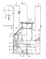
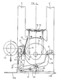
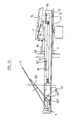
- the "drawer” 1 consists of a rectangular volume comprising on the one hand a circular depression 2 intended to receive a disc 3 which is deposited there by the user and on the other hand, two side members 5, 5 ⁇ intended to guide and ensuring, relative to the chassis 100 of the device, the translational movement of the drawer 1 when it opens and closes.
- the translation of the drawer is ensured by a reversible electric motor, not shown, driving a gear 10 cooperating with a rack 12 secured to one of the side members 5 and therefore of the drawer 1.
- three slots 20, 21, 22 are made. of appropriate shapes and each intended to allow and optionally guide the movement of an axis or stud 23, 24, 25.
- These axes or studs are themselves intended to cooperate with the periphery of the discs with a diameter smaller than those for which the depression 2 is designed so as to ensure centering with respect to said depression during the translational movement bringing the disc above its drive plate with a view to placing it in the operative position.
- these three pins are each mounted at the end of a support 27, 28, 29, these three supports seeing their movements coordinated because of their connection to each of their other ends by a common axis 30 .
- the support 29 is a lever which pivots around an axis 31 mounted on the back of the circular depression 2 and is held there by a broken ring.
- a spring 32 the ends of which are respectively connected to the box of the drawer 1 and to the end of the support 27 carrying the stud 23, ensures an elastic return of the three supports in the position shown in FIG. 2 as soon as they are moved away from it.
- a tab 35 is provided, the low level of which is lower than that of the drawer 1 and which is intended to cooperate with the fixed profile 37, mounted on the frame 100 of the reading device (FIGS. 4, 5 and 7) .
- the support 27 carries an axis 40 - see Figure 2 - intended to cooperate with a cam 42 integrally connected to a rack 12 ensuring the translation of the drawer 1 - see Figure 11 .
- the rack 12 is connected to the spar 5 of the drawer 1 by means of pins 60 and slots 61 through which said pins pass (FIGS. 5, 10 and 11) so as to obtain: - a relative movement of the rack relative to the drawer, - a movement integral with the rack and the drawer for the translation of the latter.
- the command for securing, respectively disengaging, the movement of the rack 12 from that of the drawer 1 is carried out as follows: - A lug 87 carried by a lever 88 pivoting about an axis 89 integral with the drawer 1 can engage in a notch 91 provided in the rack 12 and this under the influence of an elastic tab 94 bearing on a stop 95 secured to the spar 5.
- the release of the lug 87 relative to the notch 91 is ensured by a lug 96 carried by the lever 88 and cooperating with a ramp 97 provided in a crosspiece 98 secured to the chassis 100 of the apparatus .
- the rack 12 having completed its relative movement (the lug 87 being in the notch 91) relative to the drawer 1, the latter is then integrally translated with the latter and ensures the transfer of the disc to its operative position.
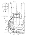
- the tab 35 cooperates with the profile 37 mounted on the chassis of the device so as to be pushed back towards the front of the device (arrow A - Figure 3). Therefore, the support 27 can no longer follow exactly the translational movement of the drawer 1 will, thanks to the connection provided by the axis 30, clockwise rotate the support 29 around the axis 31 and move the support laterally 28. In this way, the three pins 23, 24, 25 will effect a coordinated movement towards the center of the depression 2 and therefore ensure the exact centering of a disc of small diameter relative to the depression 2 provided to ensure the centering of a large diameter disc (12.5 cms) - figure 4.
- the profile 37 is dimensioned so that at the end of the translation of the drawer 1 and therefore of the movement of the placing in the operative position of the disc 3 correctly centered, the support 27 can undergo a slight return movement under the influence of the spring 32 so as to slightly release the three pins 23, 24, 25 from the periphery of the disc 3 to allow free rotation in the operative position.
- the support 27 keeps the three pins 23, 24, 25 clear at all times, that is to say at a certain distance from the periphery of the disc 3 since the disc is finally always correctly centered on its drive means by the usually conical shape of the means forming part of the drive plate 85.
- the means or supports ensuring the descent, respectively the ascent of the disc on or from the drive plate are actuated.
- this vertical movement is ensured (FIG. 5) by the combination of a plate 70 supporting the disc 3, subjected to the influence of a spring 71 and pivoting around an axis 72 and an arm 74 pivoting about an axis 76 and subjected to the influence of a spring 78.
- the drawer 1 comprises a ramp, not shown, allowing the pivoting of an arm 74 downwards and therefore, by the action of the stop 80 which it carries, the descent of the plate 70 at the end of the "front" stroke of said drawer , which ensures the positioning of the disc 3 on its drive means 85, the plate 70 then being sufficiently clear of the disc to allow free rotation.
- the cam 42 by virtue of the action of its profiles 44 then 43, brings the axis 40 towards the outer edge of the drawer, and this, against the spring 32 so as to completely spread outwards the three pins to release the vacuum 2 and allow, after removal of the disc 3 of small diameter, the positioning of a disc 3 of large diameter ( Figures 1 and 2).
- the fork 45 while maintaining the axis 40 in the position shown in Figure 7, prevents the profile 37 from cooperating with the plate 35 and therefore the supports 27, 28, 29 and therefore the pins 23, 24, 25 do not undergo no displacement and the free rotation of the disc is ensured.
- this embodiment advantageously provides a combination of the device described above with the patent subject loading system No. 905 639 of the Applicant to which one will advantageously refer to any explanation as to its operation.
- the bottom of the depression 2 partly consists of a support 120 pivoting about an axis 122 and having laterally an axis 124 intended to cooperate with the profile 127 of a cam 126 integral with the rack 12 - see FIG. 10.
- the profile 127 acts on the axis 124 to ensure the pivoting downwards or upwards, and this, depending on the direction of translation of the rack 12, of the support 120 ensuring the raising or lowering of the angular disk 3 as provided in the Belgian patent No. 905 639 of the applicant.
- the rack and the drawer are linked by means allowing them an initial relative movement during which the diameter of the disc is detected.
- the drawer is not driven in motion until after this phase.
- the rack 200 driving the drawer 1 is here integral with said drawer and therefore the rotation of the gear 204 immediately ensures the movements of the drawer.
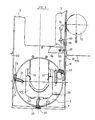
- the drawer 1 comprises three supports 27, 28 and 29 each having at one of their ends a stud 23, 24 and 25, cooperating with the periphery of the disc placed by the user.
- One of these supports, in this case 27, is also used to detect the diameter of the disc using an extension 211 supporting an axis 212 cooperating with the fixed guide 206. This same support 27 is subjected to the action of elastic means 32 anchored to the drawer 1.
- the guide 206 has two channels 216, 218 intended to guide the axis 212 as well as a stop 220.
- the drawer After positioning of a disc by the user, the drawer is translated towards the interior of the device, either automatically or in response to a command from the user, using a motor (not shown) driving the gear 204.
- a motor not shown
- the elastic means 32 tend to pivot the support 27 clockwise and in the case where the disc is of small diameter, this pivoting will be such that the axis 212 will run through the channel 218 to come against the stop 220.
- the stud 23 coming against the periphery of this disc performs only a very slight pivoting and consequently the axis 212 will follow the channel 216, which by its dimensioning brings the support 27 in the inoperative position and therefore the stud 23 away from the periphery of the disc to allow free rotation.
- the stud 23 could pivot but by a lesser angle than if it were a disc of smaller diameter.
- the device can also center a disc with an intermediate diameter.
Landscapes
- Feeding And Guiding Record Carriers (AREA)
Applications Claiming Priority (2)
| Application Number | Priority Date | Filing Date | Title |
|---|---|---|---|
| BE8700386 | 1987-04-13 | ||
| BE8700386A BE1000472A4 (fr) | 1987-04-13 | 1987-04-13 | Dispositif automatique de chargement de disques de diametres differents sur les plateaux rotatifs de tourne-disques. |
Publications (3)
| Publication Number | Publication Date |
|---|---|
| EP0286770A2 true EP0286770A2 (de) | 1988-10-19 |
| EP0286770A3 EP0286770A3 (en) | 1989-01-11 |
| EP0286770B1 EP0286770B1 (de) | 1991-11-21 |
Family
ID=3882609
Family Applications (1)
| Application Number | Title | Priority Date | Filing Date |
|---|---|---|---|
| EP87870172A Expired - Lifetime EP0286770B1 (de) | 1987-04-13 | 1987-12-09 | Vorrichtung zur automatischen Zentrierung von Platten von verschiedenen Durchmessern auf die Lademittel eines Plattenspielers |
Country Status (6)
| Country | Link |
|---|---|
| US (1) | US4839880A (de) |
| EP (1) | EP0286770B1 (de) |
| JP (1) | JPH07118139B2 (de) |
| KR (1) | KR880013134A (de) |
| BE (1) | BE1000472A4 (de) |
| DE (1) | DE3774699D1 (de) |
Cited By (5)
| Publication number | Priority date | Publication date | Assignee | Title |
|---|---|---|---|---|
| EP0265410A3 (de) * | 1986-10-22 | 1989-07-19 | Staar Sa | Lade- und -Entladegerät für Plattenspieler. |
| EP0331663A3 (de) * | 1988-03-02 | 1990-09-26 | Staar Societe Anonyme | Automatischer Platenn-Zentriermechanismus |
| EP0434136A1 (de) * | 1989-12-20 | 1991-06-26 | Koninklijke Philips Electronics N.V. | Plattenspieler sowie Zentriervorrichtung zum Gebrauch in dem Plattenspieler |
| EP0653751A3 (de) * | 1993-11-12 | 1995-07-19 | Nakamichi Corp | Vorrichtung zum Antrieb von Plattenträgern in Plattenspielern. |
| EP0685842A3 (de) * | 1994-06-01 | 1996-12-04 | Aiwa Co | Automatischer Plattenwechsler. |
Families Citing this family (15)
| Publication number | Priority date | Publication date | Assignee | Title |
|---|---|---|---|---|
| JPH067491Y2 (ja) * | 1988-05-16 | 1994-02-23 | 武美 小岩 | 回転ディスク装着機構 |
| BE1002664A3 (fr) * | 1988-11-17 | 1991-04-30 | Staar Sa | Dispositif de chargement, d'ejection et de centrage pour disques de diametres differents. |
| DE3843991A1 (de) * | 1988-12-27 | 1990-07-05 | Thomson Brandt Gmbh | Aufnahmevorrichtung fuer ein aufzeichnungs- und/oder wiedergabegeraet |
| JPH02183458A (ja) * | 1989-01-09 | 1990-07-18 | Clarion Co Ltd | ディスクローディング機構 |
| US5226028A (en) * | 1989-02-16 | 1993-07-06 | Pioneer Electronic Corporation | Centering mechanism for automotive disk player |
| DE4004562B4 (de) * | 1989-02-16 | 2008-05-08 | Pioneer Electronic Corp. | In ein Fahrzeug eingebauter Plattenspieler |
| US4933927A (en) * | 1989-02-24 | 1990-06-12 | Conner Peripherals, Inc. | Disk centering method and apparatus for centering disks for disk drives |
| JPH0697532B2 (ja) * | 1989-03-03 | 1994-11-30 | パイオニア株式会社 | ディスク再生装置 |
| JPH0679405B2 (ja) * | 1989-08-11 | 1994-10-05 | パイオニア株式会社 | ディスク再生装置 |
| US5043973A (en) * | 1990-07-30 | 1991-08-27 | Conner Peripherals, Inc. | Disk centering method and apparatus for centering disks for disk drives |
| KR970006819B1 (ko) * | 1992-11-30 | 1997-04-30 | 대우전자 주식회사 | 멀티 디스크 플레이어의 로딩(loading) 장치 |
| JP3404925B2 (ja) * | 1994-10-24 | 2003-05-12 | ミツミ電機株式会社 | ディスク装置 |
| JP3410997B2 (ja) * | 1999-10-06 | 2003-05-26 | 株式会社ソニー・コンピュータエンタテインメント | ディスク装置、およびディスクトレー |
| JP4271192B2 (ja) * | 2005-01-24 | 2009-06-03 | 富士通テン株式会社 | ディスクチェンジャ |
| CN111375710B (zh) * | 2020-03-29 | 2021-08-27 | 贺平 | 一种钢筋笼加工模具 |
Family Cites Families (11)
| Publication number | Priority date | Publication date | Assignee | Title |
|---|---|---|---|---|
| GB615993A (de) * | 1945-04-18 | |||
| US3305239A (en) * | 1964-10-19 | 1967-02-21 | Zenith Radio Corp | Position trip |
| US3345775A (en) * | 1965-08-25 | 1967-10-10 | Diebold Inc | Fire door |
| US4098510A (en) * | 1976-03-02 | 1978-07-04 | Sony Corporation | Record player |
| JPS5830665B2 (ja) * | 1976-11-24 | 1983-06-30 | ソニー株式会社 | オ−トプレ−ヤに於けるレコ−ド盤の集中装置 |
| JPS57130262A (en) * | 1981-02-05 | 1982-08-12 | Pioneer Electronic Corp | Auto loading record player |
| BE892952A (fr) * | 1982-04-23 | 1982-08-16 | Staar Sa | Dispositif automatique pour tourne-disques de mise en position operative d'un disque. |
| BE895735A (fr) * | 1983-01-28 | 1983-05-16 | Staar Sa | Dispositif automatique de mise en position operative d'un disque dans un tourne-disque |
| JPS59142935U (ja) * | 1983-03-11 | 1984-09-25 | パイオニア株式会社 | オ−トロ−デイングデイスクプレ−ヤ |
| US4680748A (en) * | 1984-12-19 | 1987-07-14 | Kabushiki Kaisha Toshiba | Recorded disk playback apparatus |
| BE902262A (fr) * | 1985-04-23 | 1985-08-16 | Staar Sa | Dispositif de chargement automatique de disques dans un tourne-disques. |
-
1987
- 1987-04-13 BE BE8700386A patent/BE1000472A4/fr not_active IP Right Cessation
- 1987-09-24 US US07/100,631 patent/US4839880A/en not_active Expired - Lifetime
- 1987-12-09 EP EP87870172A patent/EP0286770B1/de not_active Expired - Lifetime
- 1987-12-09 DE DE8787870172T patent/DE3774699D1/de not_active Expired - Fee Related
- 1987-12-25 JP JP62327543A patent/JPH07118139B2/ja not_active Expired - Fee Related
- 1987-12-28 KR KR1019870015053A patent/KR880013134A/ko not_active Withdrawn
Cited By (6)
| Publication number | Priority date | Publication date | Assignee | Title |
|---|---|---|---|---|
| EP0265410A3 (de) * | 1986-10-22 | 1989-07-19 | Staar Sa | Lade- und -Entladegerät für Plattenspieler. |
| EP0331663A3 (de) * | 1988-03-02 | 1990-09-26 | Staar Societe Anonyme | Automatischer Platenn-Zentriermechanismus |
| EP0434136A1 (de) * | 1989-12-20 | 1991-06-26 | Koninklijke Philips Electronics N.V. | Plattenspieler sowie Zentriervorrichtung zum Gebrauch in dem Plattenspieler |
| EP0653751A3 (de) * | 1993-11-12 | 1995-07-19 | Nakamichi Corp | Vorrichtung zum Antrieb von Plattenträgern in Plattenspielern. |
| US5574711A (en) * | 1993-11-12 | 1996-11-12 | Nakamichi Corporation | Device for driving trays in disk players |
| EP0685842A3 (de) * | 1994-06-01 | 1996-12-04 | Aiwa Co | Automatischer Plattenwechsler. |
Also Published As
| Publication number | Publication date |
|---|---|
| US4839880A (en) | 1989-06-13 |
| EP0286770B1 (de) | 1991-11-21 |
| JPS63257952A (ja) | 1988-10-25 |
| JPH07118139B2 (ja) | 1995-12-18 |
| KR880013134A (ko) | 1988-11-30 |
| BE1000472A4 (fr) | 1988-12-20 |
| EP0286770A3 (en) | 1989-01-11 |
| DE3774699D1 (de) | 1992-01-02 |
Similar Documents
| Publication | Publication Date | Title |
|---|---|---|
| EP0286770B1 (de) | Vorrichtung zur automatischen Zentrierung von Platten von verschiedenen Durchmessern auf die Lademittel eines Plattenspielers | |
| FR2488714A1 (fr) | Cassette a disque magnetique souple | |
| FR2563650A1 (fr) | Appareil de chargement pour un lecteur de disque | |
| FR2488715A1 (fr) | Cassette a disque magnetique souple et appareil d'enregistrement et/ou de reproduction utilisant un tel disque | |
| EP0541503B1 (de) | Transportvorrichtung für einen Informationsträger | |
| FR2702078A1 (fr) | Assemblage pour électrophone avec un plateau mobile. | |
| FR2653259A1 (fr) | Dispositif de chargement de disque pour lecteur de disque. | |
| BE1001388A6 (fr) | Mecanisme de centrage automatique de disques. | |
| FR2539543A1 (fr) | Dispositif de verrouillage pour appareils tourne-disques | |
| FR2551578A1 (fr) | Appareil d'enregistrement et/ou de lecture de disque souple | |
| FR2692071A1 (fr) | Tourne-disque. | |
| FR2728378A1 (fr) | Dispositif de mise en rotation pour la lecture d'un disque optique | |
| FR2519176A1 (fr) | Dispositif de positionnement et de verrouillage pour disques porteurs d'informations | |
| EP0183672A2 (de) | Aufnahme- und Wiedergabegerät mit Fronteinschub | |
| FR2504304A1 (fr) | Dispositif automatique de retournement du disque dans un appareil tourne-disque | |
| FR2559938A1 (fr) | Appareil pour la reproduction et/ou l'enregistrement successif et/ou selectif de disques porteurs d'informations | |
| CH628456A5 (fr) | Appareil automatique de changement de disques. | |
| FR2619651A1 (fr) | Dispositif de changement automatique de cassette | |
| EP0415805B1 (de) | Pfandvorrichtung für schiebbare Einkaufwagen und damit versehene Einkaufswagen | |
| FR2693022A1 (fr) | Tourne-disque. | |
| EP0369859B1 (de) | Verfahren zum spielfreien Antrieb einer magnetischen Bandkassette | |
| FR2479527A1 (fr) | Appareil de retournement automatique de cassettes | |
| BE882542A (fr) | Appareil de retournement automatique de cassettes | |
| EP0783166B1 (de) | Prüfungs- und Zentrierungsvorrichtung zum Einlegen von Kassetten | |
| FR2557346A1 (fr) | Dispositif de positionnement et de blocage de disques dans un logement |
Legal Events
| Date | Code | Title | Description |
|---|---|---|---|
| PUAI | Public reference made under article 153(3) epc to a published international application that has entered the european phase |
Free format text: ORIGINAL CODE: 0009012 |
|
| AK | Designated contracting states |
Kind code of ref document: A2 Designated state(s): BE CH DE FR GB IT LI NL SE |
|
| PUAL | Search report despatched |
Free format text: ORIGINAL CODE: 0009013 |
|
| AK | Designated contracting states |
Kind code of ref document: A3 Designated state(s): BE CH DE FR GB IT LI NL SE |
|
| 17P | Request for examination filed |
Effective date: 19890124 |
|
| 17Q | First examination report despatched |
Effective date: 19900927 |
|
| GRAA | (expected) grant |
Free format text: ORIGINAL CODE: 0009210 |
|
| AK | Designated contracting states |
Kind code of ref document: B1 Designated state(s): BE CH DE FR GB IT LI NL SE |
|
| ITF | It: translation for a ep patent filed | ||
| PG25 | Lapsed in a contracting state [announced via postgrant information from national office to epo] |
Ref country code: SE Effective date: 19911121 Ref country code: NL Effective date: 19911121 |
|
| GBT | Gb: translation of ep patent filed (gb section 77(6)(a)/1977) | ||
| PG25 | Lapsed in a contracting state [announced via postgrant information from national office to epo] |
Ref country code: LI Effective date: 19911231 Ref country code: CH Effective date: 19911231 Ref country code: BE Effective date: 19911231 |
|
| REF | Corresponds to: |
Ref document number: 3774699 Country of ref document: DE Date of ref document: 19920102 |
|
| NLV1 | Nl: lapsed or annulled due to failure to fulfill the requirements of art. 29p and 29m of the patents act | ||
| BERE | Be: lapsed |
Owner name: S.A. STAAR Effective date: 19911231 |
|
| REG | Reference to a national code |
Ref country code: CH Ref legal event code: PL |
|
| PLBE | No opposition filed within time limit |
Free format text: ORIGINAL CODE: 0009261 |
|
| STAA | Information on the status of an ep patent application or granted ep patent |
Free format text: STATUS: NO OPPOSITION FILED WITHIN TIME LIMIT |
|
| 26N | No opposition filed | ||
| REG | Reference to a national code |
Ref country code: GB Ref legal event code: 746 Effective date: 19991116 |
|
| REG | Reference to a national code |
Ref country code: GB Ref legal event code: IF02 |
|
| PGFP | Annual fee paid to national office [announced via postgrant information from national office to epo] |
Ref country code: DE Payment date: 20031218 Year of fee payment: 17 |
|
| PGFP | Annual fee paid to national office [announced via postgrant information from national office to epo] |
Ref country code: GB Payment date: 20041215 Year of fee payment: 18 |
|
| PGFP | Annual fee paid to national office [announced via postgrant information from national office to epo] |
Ref country code: FR Payment date: 20041216 Year of fee payment: 18 |
|
| PG25 | Lapsed in a contracting state [announced via postgrant information from national office to epo] |
Ref country code: DE Free format text: LAPSE BECAUSE OF NON-PAYMENT OF DUE FEES Effective date: 20050701 |
|
| PG25 | Lapsed in a contracting state [announced via postgrant information from national office to epo] |
Ref country code: IT Free format text: LAPSE BECAUSE OF NON-PAYMENT OF DUE FEES;WARNING: LAPSES OF ITALIAN PATENTS WITH EFFECTIVE DATE BEFORE 2007 MAY HAVE OCCURRED AT ANY TIME BEFORE 2007. THE CORRECT EFFECTIVE DATE MAY BE DIFFERENT FROM THE ONE RECORDED. Effective date: 20051209 Ref country code: GB Free format text: LAPSE BECAUSE OF NON-PAYMENT OF DUE FEES Effective date: 20051209 |
|
| GBPC | Gb: european patent ceased through non-payment of renewal fee |
Effective date: 20051209 |
|
| PG25 | Lapsed in a contracting state [announced via postgrant information from national office to epo] |
Ref country code: FR Free format text: LAPSE BECAUSE OF NON-PAYMENT OF DUE FEES Effective date: 20060831 |
|
| REG | Reference to a national code |
Ref country code: FR Ref legal event code: ST Effective date: 20060831 |