EP0287018A2 - Etiqueteuse avec contrôle d'impression - Google Patents
Etiqueteuse avec contrôle d'impression Download PDFInfo
- Publication number
- EP0287018A2 EP0287018A2 EP88105747A EP88105747A EP0287018A2 EP 0287018 A2 EP0287018 A2 EP 0287018A2 EP 88105747 A EP88105747 A EP 88105747A EP 88105747 A EP88105747 A EP 88105747A EP 0287018 A2 EP0287018 A2 EP 0287018A2
- Authority
- EP
- European Patent Office
- Prior art keywords
- pallet
- reading head
- rotor
- removal
- labeling device
- Prior art date
- Legal status (The legal status is an assumption and is not a legal conclusion. Google has not performed a legal analysis and makes no representation as to the accuracy of the status listed.)
- Granted
Links
Images


Classifications
-
- B—PERFORMING OPERATIONS; TRANSPORTING
- B65—CONVEYING; PACKING; STORING; HANDLING THIN OR FILAMENTARY MATERIAL
- B65C—LABELLING OR TAGGING MACHINES, APPARATUS, OR PROCESSES
- B65C9/00—Details of labelling machines or apparatus
- B65C9/40—Controls; Safety devices
-
- B—PERFORMING OPERATIONS; TRANSPORTING
- B65—CONVEYING; PACKING; STORING; HANDLING THIN OR FILAMENTARY MATERIAL
- B65C—LABELLING OR TAGGING MACHINES, APPARATUS, OR PROCESSES
- B65C9/00—Details of labelling machines or apparatus
- B65C9/08—Label feeding
- B65C9/12—Removing separate labels from stacks
- B65C9/16—Removing separate labels from stacks by wetting devices
-
- B—PERFORMING OPERATIONS; TRANSPORTING
- B65—CONVEYING; PACKING; STORING; HANDLING THIN OR FILAMENTARY MATERIAL
- B65C—LABELLING OR TAGGING MACHINES, APPARATUS, OR PROCESSES
- B65C9/00—Details of labelling machines or apparatus
- B65C9/46—Applying date marks, code marks, or the like, to the label during labelling
-
- Y—GENERAL TAGGING OF NEW TECHNOLOGICAL DEVELOPMENTS; GENERAL TAGGING OF CROSS-SECTIONAL TECHNOLOGIES SPANNING OVER SEVERAL SECTIONS OF THE IPC; TECHNICAL SUBJECTS COVERED BY FORMER USPC CROSS-REFERENCE ART COLLECTIONS [XRACs] AND DIGESTS
- Y10—TECHNICAL SUBJECTS COVERED BY FORMER USPC
- Y10T—TECHNICAL SUBJECTS COVERED BY FORMER US CLASSIFICATION
- Y10T156/00—Adhesive bonding and miscellaneous chemical manufacture
- Y10T156/17—Surface bonding means and/or assemblymeans with work feeding or handling means
- Y10T156/1702—For plural parts or plural areas of single part
- Y10T156/1744—Means bringing discrete articles into assembled relationship
- Y10T156/1768—Means simultaneously conveying plural articles from a single source and serially presenting them to an assembly station
-
- Y—GENERAL TAGGING OF NEW TECHNOLOGICAL DEVELOPMENTS; GENERAL TAGGING OF CROSS-SECTIONAL TECHNOLOGIES SPANNING OVER SEVERAL SECTIONS OF THE IPC; TECHNICAL SUBJECTS COVERED BY FORMER USPC CROSS-REFERENCE ART COLLECTIONS [XRACs] AND DIGESTS
- Y10—TECHNICAL SUBJECTS COVERED BY FORMER USPC
- Y10T—TECHNICAL SUBJECTS COVERED BY FORMER US CLASSIFICATION
- Y10T156/00—Adhesive bonding and miscellaneous chemical manufacture
- Y10T156/17—Surface bonding means and/or assemblymeans with work feeding or handling means
- Y10T156/1702—For plural parts or plural areas of single part
- Y10T156/1744—Means bringing discrete articles into assembled relationship
- Y10T156/1768—Means simultaneously conveying plural articles from a single source and serially presenting them to an assembly station
- Y10T156/1771—Turret or rotary drum-type conveyor
- Y10T156/1773—For flexible sheets
Definitions
- the invention relates to a labeling device with a pallet rotor that has pallet surfaces, with a label magazine for feeding labels to the pallet rotor, with a gripper cylinder that removes the labels removed from the pallet rotor from the pallet rotor and with a printing unit that is located between the label magazine and the gripper cylinder is arranged to create an imprint on the labels.
- Labeling devices of this type are known. Regarding the general state of the art, reference is made to DE-AS 21 41 306 or DE-PS 20 10 652. Such labeling devices are used to remove labels from a label magazine and to convey them further via a gripper cylinder in such a way that they are attached to the bottles, for example when filling bottles.
- the centerpiece of such labeling devices is a pallet rotor, which has pallet surfaces that are first moved past a glue roller and are thereby covered with a thin film of glue. These glued pallet surfaces then run past a label magazine, where they remove the foremost label. As the pallet surfaces move on, the labels that are then picked up are guided past a printing unit. The printing unit puts a code or a date, for example the date of filling, on the labels.
- the labels are transported from the printing unit to a gripper cylinder, which removes the labels from the Pallet areas decreases and then rotated on the transport path of the containers to be labeled, such as bottles.
- bottles for which the bottling date is missing may in some cases not be allowed to be sold abroad in accordance with legal regulations. If one takes into account in this context that modern labeling devices of the type described work with up to 21 labeling processes per second, it is clear that even if the system continues to malfunction even briefly, considerable damage occurs, since that with the bottles with defective labels cannot be placed on the market.
- the invention has for its object to provide a labeling device of the type mentioned, in which the occurrence of errors in the printing unit can be determined.
- a reading head for checking the printing is arranged between the printing unit and the gripper cylinder.
- the read head can be connected to a device that, for example, shuts down the system if there are several labels without one another Imprint appear.
- the signal from the reading head can also be used, for example if it does not occur continuously, but only occasionally, so that the bottle provided with this label is subsequently ejected.
- the errors in the printing unit can be determined very reliably, because the reading conditions for the reading head itself are best in the area of the pallet carousel. Since the pallet surfaces run with high precision (with deviations of a maximum of 100th of a mm), the assignment of the pallet surfaces to the reading head can be maintained very precisely. The reading head can therefore be adjusted accordingly and then always detects the individual labels at the same point, namely in the area in which the print should be applied. If the inspection were carried out at the bottle table, this would lead to difficult reading conditions due to inaccuracies due to bottle and position tolerances.
- any reading head suitable for this purpose can be used as the reading head. So it is possible to use electro-optical read heads or magnetic read heads. Simple diffuse sensors (in the manner of light barriers) can be used as the electro-optical read head. With such simple reflex light scanners it can be determined whether a print is available or Not. However, a more complex solution can also be to use an optical camera as a reading head, which can then not only determine the presence or absence of the print, but is also able to read the print.
- printing units i.a. Type wheel printers, laser dating, laser printers, inkjet dating, heated stamps can be used.
- the invention can be used for all labeling devices of the type mentioned, the pallet surfaces either being mounted on a rotary cylinder, but it can also be used for labeling devices in which the pallet rotor has upright individual pallet shafts, each of which carries at least one circular-shaped removal pallet and which have a control curve leading the outer surfaces of the individual removal pallets past the reading head.
- the invention can also be used in labeling devices in which the radius of curvature of the removal pallets is smaller than the radius of curvature of the pallet orbit, the control curve then being designed in such a way that it controls the removal pallets in an oscillating movement.
- the control curve is advantageously designed in such a way that the center of curvature of the individual pallets swings in a circular path around the eye of the reading head. This solution is preferably used when the read head allows only small tolerances in its distance from the imprint to be read, ie when the read head is sensitive to depth of field.
- This type of control of the individual pallets ensures that the part of the print that the eye is reading when the print moves past is always at a constant distance from the eye or the focal point of the read head, so that the read head can be focused on the distance and then enables precise observation.
- Another embodiment of the control curve can provide that the center of curvature of the individual pallets is stationary on the connecting line between the pallet rotor axis and the eye when the outer surface is pivoted past the reading head.
- This solution has the advantage that the eye always looks vertically at the respective part of the print that has just moved past, so that regardless of the length of the print it can be observed exactly with reflected light.
- this solution requires a rapid swiveling movement of the individual pallets in the case of the rapid rotary movements of the pallet rotors of this type, which entails correspondingly higher forces.
- a currently preferred embodiment therefore provides that the print is applied symmetrically to the central axis of the circular cut-out removal pallet on the labels and that the control curve is designed such that the central axis of the circular cut-out removal pallet when the leading edge of the print runs in before the eye of the reading head in the radial direction of the pallet rotor and remains aligned in the radial direction of the pallet rotor until the trailing edge of the print has passed the eye of the reading head.
- the individual pallets are held in this solution after taking the aligned position, in which the central axis of the removal pallets and thus also the print center is aligned with the radial direction, and then moved past the reading head in the fixed position. This results in low forces for controlling the Individual pallets, on the other hand, a slight restriction in the width of the imprint is accepted, since the reflected light beam can only be detected by the reading head in a certain angular range.
- FIG. 1 The plan view of the labeling device according to the invention is shown schematically in FIG. 1, the labeling device overall being designated by reference number 1.
- the core of the labeling device is the Pallet rotor 2, which has removal pallets 4 lying at equal angular intervals from one another, eight removal pallets are shown in the exemplary embodiment shown.
- the removal pallets sit on pallet shafts 11 which are acted upon by control cams which are not shown in detail in such a way that the pallet surfaces 3 of the removal pallets are pivoted back and forth during a revolution in accordance with a movement path predetermined by a control curve.
- control cams which are not shown in detail in such a way that the pallet surfaces 3 of the removal pallets are pivoted back and forth during a revolution in accordance with a movement path predetermined by a control curve.
- the pallet rotor 2 which carries the individual pivoting about the pallet shafts 11 removal pallets 4, rotates in the direction of arrow P1 at high speed during operation.
- the glue roller 7 carries a thin film of glue onto the pallet surfaces 3 which are curved in the form of a circular section.
- the glued pallet surfaces 3 then run past the front surface of the label magazine 6, where they remove the label lying in front.
- the label adhering to a pallet surface is then guided past a printing unit 8.
- the printing unit 8 prints the filling date at a predetermined location on the label.
- the label arrives at the gripper cylinder 5, which pulls the label off the pallet surface and then passes it on to the objects to be labeled, for example bottles, in a known manner.
- the processes described so far are known.
- the invention now provides that between the printing unit 8 and the gripper cylinder 5 a reading head 10 is arranged, which checks the imprint applied by the printing unit 8.
- the reading head can either determine whether a print has taken place at the examined location or, for example, if the read head 10 consists of a camera, it can also recognize which print has been applied.
- the arrangement of the reading head 10 in the area of the pallet rotor enables an exact check of the point at which the date imprint should be attached, since the removal pallets in the pallet rotor and thus also the removed labels pass through a highly precise path. The reading head 10 can thus reliably determine whether the printing unit 8 is working correctly.
- the reading head 10 determines that no printing has taken place at the location provided for the printing, it can emit a corresponding signal via the signal line 9, which signal can then be used for further control of the system. For example, an optical or acoustic alarm signal can be generated from a signal on signal line 9. It is also possible, if a non-existent imprint is found only once, that the corresponding bottle with the defective label is subsequently automatically excreted or that the entire system is shut down if several labels are found by the read head 10 without imprint. The removal pallets 4 must be guided past the reading head 10 in such a way that it can reliably carry out the overprint check. Depending on the type of reading head used, different paths of movement of the removal pallets past the reading head are conceivable or suitable.
- the embodiment shown in Figure 2 explained a case in which a read head 10 is used which is sensitive to depth of field, ie which allows only a small tolerance with regard to the distance to the object to be read for precise work.
- the reading head 10 is oriented such that its optical axis points to the center point M P of the pallet rotor (axis of rotation of the pallet rotor).
- the position of the read head 10 at which the read head detects the signal is referred to in the text as "eye of the read head” and is indicated by 12 in FIG. 2. This can be, for example, the focal point of a taking lens which is arranged in the front of the reading head.
- the radius of curvature r u of the orbit of the pallets is greater than the radius of curvature r E of the individual removal pallets 4.
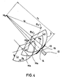
- the radius of curvature of the orbit of the pallets is understood to mean the radius r u shown in FIG. 4, ie the radius of the circumference around the pallets in the middle position.
- the pivot axis, ie the axis of the pallet waves is shown in Figures 2 through 4 designated by S E and passes through the web B2.
- the reading head 10 in the embodiment shown in FIG. 2 can observe at a constant distance a from its optical eye 12, the center of curvature K E of the pallet surfaces 3 of the removal pallets is guided around a circular path B 1 around the optical eye 12 in this embodiment.
- the removal pallet is pivoted in the direction of the arrow P2. A second possibility of moving the removal pallet 4 past the reading head 10 is shown in FIG.
- FIG. 4 Shown in Figure 4 are now three layers L1, L2, L3, which are run through in this order by the individual removal pallets 4.
- the position L 1 shows the removal pallet moving towards the reading head 10, its central axis M A pointing away from the center M P of the pallet rotor.
- the control curve is now designed so that the removal pallet from this position L1 is first pivoted back in the direction of the arrow P4 until the central axis M A points to the center M P of the pallet rotor. This position is taken up by the removal pallet at the latest when the leading edge 14 of the print runs into the reading area of the reading head 10.
- the removal pallet is not pivoted forward or backward after reaching this position (position L2), rather the center of curvature K E is guided on a circular path B3 around the center point M P of the pallet rotor, ie the removal pallet is moved further together with the rotor, without its central axis M A performing a pivoting movement with respect to the radial direction of the rotor.
- This holding of the removal pallets continues until the subsequent edge 15 of the imprint 13 has run out of the reading area of the reading head 10.
- the movement sequence described with reference to FIG. 4 has the advantage that the acting forces are very low because the removal pallets are not pivoted. However, the distance with which the reading head 10 reads the imprint changes during the reading process, the reading distance being greatest at the leading and trailing edges and smallest at the center of the imprint. It will then come up with this solution Read head 10 used, the tolerance with respect to the permissible depth of field is greater than or equal to this reading distance change.
- the invention is not limited to pallet rotors that work with individual removal pallets whose radii of curvature are smaller than the radii of curvature r u of the pallet orbit.
- the invention can also be used in the same way for pallet rotors that work with removal pallets in which the radii of curvature are of the same size and can also be used for those pallet rotors that consist of rotating cylinders and have pallet surfaces on the outer circumference.
- the term “reading head” is also to be understood in the broadest sense, in particular magnetic reading heads are also intended to be included, which can be used when the printer is working with magnetizable ink liquid.
- cameras can also be used as optical reading heads. It is also conceivable to use the end of an optical light guide as the reading head, which then leads the light to a detection point further away.
Landscapes
- Labeling Devices (AREA)
Applications Claiming Priority (2)
| Application Number | Priority Date | Filing Date | Title |
|---|---|---|---|
| DE3712554 | 1987-04-13 | ||
| DE19873712554 DE3712554A1 (de) | 1987-04-13 | 1987-04-13 | Etikettiergeraet mit druckwerkkontrolle |
Publications (3)
| Publication Number | Publication Date |
|---|---|
| EP0287018A2 true EP0287018A2 (fr) | 1988-10-19 |
| EP0287018A3 EP0287018A3 (en) | 1989-06-14 |
| EP0287018B1 EP0287018B1 (fr) | 1993-07-28 |
Family
ID=6325563
Family Applications (1)
| Application Number | Title | Priority Date | Filing Date |
|---|---|---|---|
| EP88105747A Expired - Lifetime EP0287018B1 (fr) | 1987-04-13 | 1988-04-11 | Etiqueteuse avec contrôle d'impression |
Country Status (5)
| Country | Link |
|---|---|
| US (1) | US4844769A (fr) |
| EP (1) | EP0287018B1 (fr) |
| JP (1) | JP2539882B2 (fr) |
| DE (2) | DE3712554A1 (fr) |
| ES (1) | ES2041727T3 (fr) |
Cited By (3)
| Publication number | Priority date | Publication date | Assignee | Title |
|---|---|---|---|---|
| EP1038781A1 (fr) * | 1999-03-24 | 2000-09-27 | KHS Maschinen- und Anlagenbau Aktiengesellschaft | Dispositif d'étiquetage |
| WO2010040512A1 (fr) * | 2008-10-07 | 2010-04-15 | Khs Ag | Procédé de test pour dispositif de contrôle, en particulier pour dispositif de contrôle de position d’étiquettes |
| CN104237250A (zh) * | 2014-09-11 | 2014-12-24 | 苏州佳祺仕信息科技有限公司 | 自动化标签检验检测组装 |
Families Citing this family (9)
| Publication number | Priority date | Publication date | Assignee | Title |
|---|---|---|---|---|
| DE4125007A1 (de) * | 1991-07-27 | 1993-01-28 | Eti Tec Maschinenbau | Etikettierstation mit laserstrahlkennzeichnung der etiketten |
| JP2751089B2 (ja) * | 1992-11-30 | 1998-05-18 | 大日本インキ化学工業株式会社 | レーザーマーキング方法及び印刷インキ |
| DK1112861T3 (da) * | 1999-12-28 | 2004-02-23 | Ferag Ag | Fremgangsmåde og anordning til forbindelse af supplerende produkter med trykkeriprodukter |
| WO2003082583A1 (fr) | 2002-03-22 | 2003-10-09 | Ap Technoglass | Systeme de marquage au laser |
| DE102007054657A1 (de) | 2006-11-15 | 2008-07-03 | Loell Industry Solutions Gmbh | Optische Erfassungseinrichtung, insbesondere zur Inspektion von Flaschen, sowie entsprechendes Visualisierungsverfahren |
| ITPR20080083A1 (it) * | 2008-12-10 | 2010-06-11 | Marco Lottici | Metodo per il controllo della posizione e/o verifica della presenza di scritte, serigrafie etichette applicate su contenitori in genere |
| EP2542477B1 (fr) | 2010-03-04 | 2014-07-30 | SIDEL S.p.A. con Socio Unico | Étiqueteuse et procédé associé |
| DE102011084798A1 (de) * | 2011-10-19 | 2013-04-25 | Krones Aktiengesellschaft | Bedruckungsvorrichtung für Behälter |
| DE102014104626A1 (de) * | 2014-04-02 | 2015-10-08 | Krones Ag | Etikettiermaschine mit Etikettendruck |
Family Cites Families (11)
| Publication number | Priority date | Publication date | Assignee | Title |
|---|---|---|---|---|
| US3954542A (en) * | 1967-12-20 | 1976-05-04 | Oliver Machinery Company | Labeling machine |
| US3651503A (en) * | 1969-07-22 | 1972-03-21 | Tag A Tron Inc | System for processing merchandizing tags having printed and magnetic information thereon |
| DE2010652C3 (de) * | 1970-03-06 | 1980-03-27 | Kronseder, Hermann, 8402 Neutraubling | Entnahmevorrichtung für Etiketten |
| US3736213A (en) * | 1970-03-06 | 1973-05-29 | Kronseder H | Label extractor in a labeling machine |
| FR2069151A5 (fr) * | 1970-03-06 | 1971-09-03 | Kronseder Hermann | |
| JPS542840A (en) * | 1977-06-08 | 1979-01-10 | Akira Washida | Socks |
| US4210481A (en) * | 1978-11-14 | 1980-07-01 | Njm, Inc. | Labeling machines |
| DE3110400A1 (de) * | 1981-03-18 | 1982-10-07 | Jagenberg-Werke AG, 4000 Düsseldorf | Etikettierstation einer etikettiermaschine und verfahren zum etikettieren von gegenstaenden |
| DE3216138C2 (de) * | 1982-04-30 | 1984-06-14 | Hermann 8404 Wörth Kronseder | Etikettiervorrichtung für Flaschen o. dgl. |
| DE3345126C3 (de) * | 1983-12-09 | 1994-07-28 | Piepenbrock Berlin Gmbh & Co K | Vorrichtung zum Aufbringen von Etiketten auf runde Behälter |
| DE3530352A1 (de) * | 1985-08-24 | 1987-03-05 | Kronseder Maschf Krones | Vorrichtung zum bedrucken von etiketten, insbesondere in etikettiermaschinen |
-
1987
- 1987-04-13 DE DE19873712554 patent/DE3712554A1/de not_active Withdrawn
-
1988
- 1988-04-08 US US07/179,508 patent/US4844769A/en not_active Expired - Lifetime
- 1988-04-11 EP EP88105747A patent/EP0287018B1/fr not_active Expired - Lifetime
- 1988-04-11 JP JP63088885A patent/JP2539882B2/ja not_active Expired - Lifetime
- 1988-04-11 DE DE8888105747T patent/DE3882568D1/de not_active Expired - Lifetime
- 1988-04-11 ES ES198888105747T patent/ES2041727T3/es not_active Expired - Lifetime
Cited By (4)
| Publication number | Priority date | Publication date | Assignee | Title |
|---|---|---|---|---|
| EP1038781A1 (fr) * | 1999-03-24 | 2000-09-27 | KHS Maschinen- und Anlagenbau Aktiengesellschaft | Dispositif d'étiquetage |
| WO2010040512A1 (fr) * | 2008-10-07 | 2010-04-15 | Khs Ag | Procédé de test pour dispositif de contrôle, en particulier pour dispositif de contrôle de position d’étiquettes |
| US8711350B2 (en) | 2008-10-07 | 2014-04-29 | Khs Gmbh | Test method for inspection device, particularly for label seating inspection device |
| CN104237250A (zh) * | 2014-09-11 | 2014-12-24 | 苏州佳祺仕信息科技有限公司 | 自动化标签检验检测组装 |
Also Published As
| Publication number | Publication date |
|---|---|
| DE3882568D1 (de) | 1993-09-02 |
| EP0287018B1 (fr) | 1993-07-28 |
| DE3712554A1 (de) | 1988-11-03 |
| ES2041727T3 (es) | 1993-12-01 |
| US4844769A (en) | 1989-07-04 |
| JP2539882B2 (ja) | 1996-10-02 |
| EP0287018A3 (en) | 1989-06-14 |
| JPS649143A (en) | 1989-01-12 |
Similar Documents
| Publication | Publication Date | Title |
|---|---|---|
| EP0576824B1 (fr) | Dispositif de contrÔle de la qualité d'impression pour machine d'impression rotative recto-verso | |
| DE60129312T2 (de) | Vorrichtung zum behandeln von bedruckten bogen | |
| EP0287018B1 (fr) | Etiqueteuse avec contrôle d'impression | |
| EP0863482B1 (fr) | Installation pour le traitement de cartes à puce et/ou magnétiques | |
| DE2938586A1 (de) | Computergesteuerte pruefvorrichtung/ pruefung von bedruckten dokumenten | |
| CH657093A5 (de) | Rotationsdruckpressen-anordnung. | |
| DE1531862A1 (de) | Vorrichtung zur automatischen Qualitaetspruefung von elektronischen Bauteilen kleiner Abmessungen | |
| WO2003070465A1 (fr) | Dispositif de transport de feuilles equipe d'un element guide-feuille | |
| DE19709561C2 (de) | Anlage zur Bearbeitung von Chip- und/oder Magnetstreifenkarten | |
| DE2943022A1 (de) | Etikettiermaschine | |
| CH683288A5 (de) | Verfahren und Vorrichtung zur Beaufschlagung bewegter Gebinde mit einem Laserstrahl. | |
| DE69719784T2 (de) | Vorrichtung und verfahren zur markierung von defekten | |
| DE68926379T2 (de) | Verfahren und Vorrichtung zum Abtasten von Strichkodes auf einem laufenden Blatt | |
| EP0947880B1 (fr) | Méthode et dispositif pour couper des bandes de matériau pourvues d'images | |
| DE4107012C2 (de) | Verfahren zum Aufbringen und Inspizieren einer optisch lesbaren Codemarkierung und Vorrichtung hierfür | |
| DE2900123C2 (de) | Etikettiermaschine | |
| DE60027668T2 (de) | Verfahren und Vorrichtung zum Wenden von Eiern | |
| DE3875404T2 (de) | Verfahren und apparat zum identifizieren, schneiden und weiterverarbeiten von dokumenten. | |
| DE3743676C2 (de) | Druck- und/oder Prägevorrichtung | |
| EP1804055A1 (fr) | Dispositif destiné à inspecter des étiquettes situées sur des récipients | |
| DE3737802A1 (de) | Vorrichtung zur automatischen entwertung von banknoten | |
| DE102009004640B4 (de) | Vorrichtung und Verfahren zum Beigeben von Belegen in Kommissionieranlagen | |
| DE19707657A1 (de) | Bogensensor | |
| DE20302578U1 (de) | Module für Etikettiermaschinen | |
| DE3331982A1 (de) | Vorrichtung fuer druckeinrichtungen zum automatischen, listenweisen trennen von faltpapier |
Legal Events
| Date | Code | Title | Description |
|---|---|---|---|
| PUAI | Public reference made under article 153(3) epc to a published international application that has entered the european phase |
Free format text: ORIGINAL CODE: 0009012 |
|
| AK | Designated contracting states |
Kind code of ref document: A2 Designated state(s): DE ES FR GB IT |
|
| PUAL | Search report despatched |
Free format text: ORIGINAL CODE: 0009013 |
|
| AK | Designated contracting states |
Kind code of ref document: A3 Designated state(s): DE ES FR GB IT |
|
| 17P | Request for examination filed |
Effective date: 19890518 |
|
| 17Q | First examination report despatched |
Effective date: 19910517 |
|
| GRAA | (expected) grant |
Free format text: ORIGINAL CODE: 0009210 |
|
| ITF | It: translation for a ep patent filed | ||
| AK | Designated contracting states |
Kind code of ref document: B1 Designated state(s): DE ES FR GB IT |
|
| ET | Fr: translation filed | ||
| REF | Corresponds to: |
Ref document number: 3882568 Country of ref document: DE Date of ref document: 19930902 |
|
| GBT | Gb: translation of ep patent filed (gb section 77(6)(a)/1977) |
Effective date: 19930818 |
|
| REG | Reference to a national code |
Ref country code: ES Ref legal event code: FG2A Ref document number: 2041727 Country of ref document: ES Kind code of ref document: T3 |
|
| PLBE | No opposition filed within time limit |
Free format text: ORIGINAL CODE: 0009261 |
|
| STAA | Information on the status of an ep patent application or granted ep patent |
Free format text: STATUS: NO OPPOSITION FILED WITHIN TIME LIMIT |
|
| 26N | No opposition filed | ||
| REG | Reference to a national code |
Ref country code: GB Ref legal event code: IF02 |
|
| PGFP | Annual fee paid to national office [announced via postgrant information from national office to epo] |
Ref country code: ES Payment date: 20020410 Year of fee payment: 15 |
|
| PG25 | Lapsed in a contracting state [announced via postgrant information from national office to epo] |
Ref country code: ES Free format text: LAPSE BECAUSE OF NON-PAYMENT OF DUE FEES Effective date: 20030412 |
|
| REG | Reference to a national code |
Ref country code: ES Ref legal event code: FD2A Effective date: 20030412 |
|
| PGFP | Annual fee paid to national office [announced via postgrant information from national office to epo] |
Ref country code: GB Payment date: 20060322 Year of fee payment: 19 |
|
| PGFP | Annual fee paid to national office [announced via postgrant information from national office to epo] |
Ref country code: DE Payment date: 20070427 Year of fee payment: 20 |
|
| GBPC | Gb: european patent ceased through non-payment of renewal fee |
Effective date: 20070411 |
|
| PGFP | Annual fee paid to national office [announced via postgrant information from national office to epo] |
Ref country code: IT Payment date: 20070625 Year of fee payment: 20 |
|
| PG25 | Lapsed in a contracting state [announced via postgrant information from national office to epo] |
Ref country code: GB Free format text: LAPSE BECAUSE OF NON-PAYMENT OF DUE FEES Effective date: 20070411 |
|
| PGFP | Annual fee paid to national office [announced via postgrant information from national office to epo] |
Ref country code: FR Payment date: 20070420 Year of fee payment: 20 |