EP0287129A1 - Strahlungsbildaufzeichnungs- und Wiedergabesystem - Google Patents
Strahlungsbildaufzeichnungs- und Wiedergabesystem Download PDFInfo
- Publication number
- EP0287129A1 EP0287129A1 EP88106155A EP88106155A EP0287129A1 EP 0287129 A1 EP0287129 A1 EP 0287129A1 EP 88106155 A EP88106155 A EP 88106155A EP 88106155 A EP88106155 A EP 88106155A EP 0287129 A1 EP0287129 A1 EP 0287129A1
- Authority
- EP
- European Patent Office
- Prior art keywords
- stimulable phosphor
- phosphor sheet
- image
- read
- radiation
- Prior art date
- Legal status (The legal status is an assumption and is not a legal conclusion. Google has not performed a legal analysis and makes no representation as to the accuracy of the status listed.)
- Granted
Links
Images




Classifications
-
- G—PHYSICS
- G03—PHOTOGRAPHY; CINEMATOGRAPHY; ANALOGOUS TECHNIQUES USING WAVES OTHER THAN OPTICAL WAVES; ELECTROGRAPHY; HOLOGRAPHY
- G03B—APPARATUS OR ARRANGEMENTS FOR TAKING PHOTOGRAPHS OR FOR PROJECTING OR VIEWING THEM; APPARATUS OR ARRANGEMENTS EMPLOYING ANALOGOUS TECHNIQUES USING WAVES OTHER THAN OPTICAL WAVES; ACCESSORIES THEREFOR
- G03B42/00—Obtaining records using waves other than optical waves; Visualisation of such records by using optical means
- G03B42/02—Obtaining records using waves other than optical waves; Visualisation of such records by using optical means using X-rays
-
- G—PHYSICS
- G01—MEASURING; TESTING
- G01T—MEASUREMENT OF NUCLEAR OR X-RADIATION
- G01T1/00—Measuring X-radiation, gamma radiation, corpuscular radiation, or cosmic radiation
- G01T1/16—Measuring radiation intensity
- G01T1/20—Measuring radiation intensity with scintillation detectors
- G01T1/2012—Measuring radiation intensity with scintillation detectors using stimulable phosphors, e.g. stimulable phosphor sheets
Definitions
- the light emitted by the stimulable phosphor sheet upon stimulation thereof is photoelectrically detected and converted to electric image signals, which are processed as desired to reproduce a visible image having an improved image quality, particularly a high diagnostic efficiency and accuracy.
- the finally obtained visible image may be reproduced in the form of a hard copy or may be displayed on a cathode ray tube (CRT).
- CRT cathode ray tube
- the stimulable phosphor sheet is used to temporarily store the radiation image in order to reproduce the final visible image therefrom on a final recording medium. For economical reasons, therefore, it is desirable that the stimulable phosphor sheet be used repeatedly.
- the radiation image recording and read-out apparatus having such a configuration, the radiation image recording and read-out can be carried out sequentially and efficiently.
- the present invention provides a first radiation image recording and read-out apparatus which comprises:
- a control circuit section 3 housing printed circuit boards or the like for controlling image processing or the like is provided inward from the loop of the recording belt 2.
- the image recording is carried out in the manner as mentioned above on the recording belt 2 inside of the recording and read-out unit 1, and then the image read-out and the erasing are carried out.
- the image read-out and the erasing need not necessarily be carried out with the recording and read-out unit 1 being disposed at its first position, and may be carried out in the course of conveyance of the recording and read-out unit 1 from its first position to its second position or may be carried out with the recording and read-out unit 1 being disposed at its second position.
- the fluoroscopic section 81 may be moved up to a position in the vicinity of the image recording table 14 as long as the recording and read-out unit 1 is being retracted to its second position. Also, the fluoroscopic section 81 may be positioned to face the radiation source 11 only in the course of the fluoroscopy and moved to a position deviated from the radiation source 11 at the time other than the fluoroscopy.
- One end side of the stimulable phosphor sheet 202 capable of storing the radiation image thereon is wound around the first wind-up shaft 241.
- the stimulable phosphor sheet 202 is formed in the long strip-like shape by use of a flexible substrate.
- the other end side of the stimulable phosphor sheet 202 is supported by the second wind-up shaft 242 so that the sheet 202 can be wound up therearound.
- the stimulable phosphor sheet 202 is applied between a roller 246 and rollers 247, 247 disposed between the first wind-up shaft 241 and the second wind-up shaft 242.
- the stimulable phosphor sheet 202 is positioned so that the flexible substrate substantially permeable to the radiation faces up and the stimulable phosphor layer overlaid on the substrate faces down.
- the stimulable phosphor sheet 202 is conveyed in the sub-scanning direction, and consequently the detection of the light emitted by the stimulable phosphor sheet 202 is carried out two-dimensionally.
- a secondary erasing light source 270 for carrying out secondary erasing is provided between the first wind-up shaft 241 and the image recording section 210.
- the secondary erasing light source 270 is composed of a light source of the same type as the erasing light sources 231, 231, ... at the erasing section 230, and is turned on to irradiate the erasing light to the stimulable phosphor sheet 202 at the time the sheet 202 is delivered from the first wind-up shaft 241 for carrying out the radiation image recording.
- the stimulable phosphor sheet 202 stores energy of radiations emitted by radioactive isotopes such as Ra226, which are contained as impurities in the stimulable phosphor, or energy of environmental radiations. These types of radiation energy undesirably stored on the stimulable phosphor sheet 202 cause noise in a radiation image recorded next on the stimulable phosphor sheet 202.
- radioactive isotopes such as Ra226, which are contained as impurities in the stimulable phosphor, or energy of environmental radiations.
- such radiation energy is erased by exposing the stimulable phosphor sheet 202 to the secondary erasing light produced by the secondary erasing light source 270.
- the secondary erasing light is intercepted by light shielding plates 281 and 282 so that the sheet 202 prior to the image read-out is not exposed thereto.
- the stimulable phosphor sheet 302 is disposed so that the stimulable phosphor layer 302B comes under the substrate 302A, and is supported in the case 307 with the holding portions 302b and 302d being slideably supported on rails 311, 311.
- the upper part of the case 307 including the rails 311, 311 is constituted as an image recording section 310 for holding the stimulable phosphor sheet 302 in the course of the radiation image recording.
- the longitudinal and transverse dimensions of the case 307 are adjusted to be slightly larger than those of the stimulable phosphor sheet 302.
- an end of the case 307 is provided with the elongated opening 307a which faces the edge face of the stimulable phosphor sheet 302.
- the substrate 302A of the stimulable phosphor sheet 302 need not necessarily be formed of a transparent material. With this configuration, the aforesaid secondary erasing can be carried out easily by the utilization of the surface type erasing light source.
- an image recording section 410 is constituted by the light shielding cover 404 at its projected-out position and the image recording table 406.
- the regions of the light shielding cover 404 outside of its upper surface are lined with a radiation absorbing material such as a lead plate so that no fog is caused to arise on the stimulable phosphor sheet 402 by environmental radiations or the like other than the radiation used for the image recording.
- the exposed portion of the stimulable phosphor sheet 402 emits light carrying the radiation image stored thereon.
- the emitted light is efficiently detected by the long photomultiplier 428 directly or after being reflected by the light guiding reflection mirror 429.
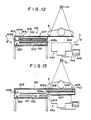
- the rails 507, 507 inside of the light shielding cover 504 are larger than the rails 509, 509 inside of the case 503, so that the rails 507, 507 slide on the rails 509, 509 and are housed in the case 503 by lying on the rails 509, 509.
- the length of the recording and read-out unit 501 as a whole becomes slightly longer than the length three times the length of a single image area on the stimulable phosphor sheet 502.
- the length of the recording and read-out unit 501 can be reduced to a length nearly equal to the length of a single image area as in the embodiment shown in Figure 12.
- the stimulable phosphor sheet 502 need not be conveyed outward from the case 503 at the time of image read-out.
Landscapes
- Physics & Mathematics (AREA)
- General Physics & Mathematics (AREA)
- Health & Medical Sciences (AREA)
- Life Sciences & Earth Sciences (AREA)
- High Energy & Nuclear Physics (AREA)
- Molecular Biology (AREA)
- Spectroscopy & Molecular Physics (AREA)
- Radiography Using Non-Light Waves (AREA)
Applications Claiming Priority (4)
| Application Number | Priority Date | Filing Date | Title |
|---|---|---|---|
| JP62094546A JP2565709B2 (ja) | 1987-04-17 | 1987-04-17 | 放射線画像情報記録読取装置 |
| JP94546/87 | 1987-04-17 | ||
| JP62094549A JPS63259642A (ja) | 1987-04-17 | 1987-04-17 | 放射線画像情報記録読取装置 |
| JP94549/87 | 1987-04-17 |
Publications (2)
| Publication Number | Publication Date |
|---|---|
| EP0287129A1 true EP0287129A1 (de) | 1988-10-19 |
| EP0287129B1 EP0287129B1 (de) | 1990-11-07 |
Family
ID=26435834
Family Applications (1)
| Application Number | Title | Priority Date | Filing Date |
|---|---|---|---|
| EP88106155A Expired EP0287129B1 (de) | 1987-04-17 | 1988-04-18 | Strahlungsbildaufzeichnungs- und Wiedergabesystem |
Country Status (3)
| Country | Link |
|---|---|
| US (1) | US4943724A (de) |
| EP (1) | EP0287129B1 (de) |
| DE (1) | DE3860970D1 (de) |
Cited By (5)
| Publication number | Priority date | Publication date | Assignee | Title |
|---|---|---|---|---|
| EP0387369A1 (de) * | 1989-03-14 | 1990-09-19 | Siemens Aktiengesellschaft | Röntgendiagnostikeinrichtung mit einem Speicherleuchtschirm |
| EP0394564A1 (de) * | 1987-11-27 | 1990-10-31 | Agfa-Gevaert N.V. | Röntgenstrahlenkassette |
| EP0554800A1 (de) * | 1992-01-31 | 1993-08-11 | Shimadzu Corporation | Röntgengerät |
| US5337341A (en) * | 1992-01-31 | 1994-08-09 | Shimadzu Corporation | X-ray radiographic apparatus |
| EP1111408A3 (de) * | 1999-12-23 | 2002-07-17 | Agfa-Gevaert AG | Vorrichtung zum Auslesen von in einer Speicherschicht abgespeicherten Informationen sowie Röntgenkassette und Röntgentisch |
Families Citing this family (5)
| Publication number | Priority date | Publication date | Assignee | Title |
|---|---|---|---|---|
| JP2002072390A (ja) * | 2000-08-31 | 2002-03-12 | Fuji Photo Film Co Ltd | 放射線画像情報記録読取装置 |
| US6675613B2 (en) * | 2001-06-18 | 2004-01-13 | Wesley Scott Ashton | Tongue and mouth stud for dispensing a substance |
| CN102770783B (zh) * | 2010-02-26 | 2016-01-20 | 富士胶片株式会社 | 放射线成像装置 |
| US10458931B1 (en) | 2016-06-17 | 2019-10-29 | Leidos, Inc. | Contact imaging sensor head for computed radiography |
| DE102020208939A1 (de) * | 2020-07-16 | 2022-01-20 | Demmeler Automatisierung Und Roboter Gmbh | Kompakte Roboterzelle |
Citations (4)
| Publication number | Priority date | Publication date | Assignee | Title |
|---|---|---|---|---|
| EP0077678A2 (de) * | 1981-10-16 | 1983-04-27 | Fuji Photo Film Co., Ltd. | Strahlungsbild-Aufzeichnungs- und Wiedergabesystem |
| EP0179411A1 (de) * | 1984-10-20 | 1986-04-30 | Fuji Photo Film Co., Ltd. | Vorrichtung für die Aufnahme und die Wiedergabe eines Strahlungsbildes |
| EP0077676B1 (de) * | 1981-10-16 | 1986-08-06 | Fuji Photo Film Co., Ltd. | Strahlungsbild-Aufzeichnungssystem |
| EP0220629A2 (de) * | 1985-10-18 | 1987-05-06 | Fuji Photo Film Co., Ltd. | Gerät zur Aufzeichnung und Auswertung von Strahlungsbildern |
Family Cites Families (3)
| Publication number | Priority date | Publication date | Assignee | Title |
|---|---|---|---|---|
| JPS58129295A (ja) * | 1982-01-27 | 1983-08-02 | 株式会社東芝 | 多分割遮蔽板 |
| JPS58207038A (ja) * | 1982-05-28 | 1983-12-02 | Hitachi Ltd | 放射線画像処理装置 |
| JPS6198340A (ja) * | 1984-10-19 | 1986-05-16 | Fuji Photo Film Co Ltd | 分割撮影可能な放射線画像情報記録読取装置 |
-
1988
- 1988-04-18 DE DE8888106155T patent/DE3860970D1/de not_active Expired - Lifetime
- 1988-04-18 US US07/182,678 patent/US4943724A/en not_active Expired - Lifetime
- 1988-04-18 EP EP88106155A patent/EP0287129B1/de not_active Expired
Patent Citations (4)
| Publication number | Priority date | Publication date | Assignee | Title |
|---|---|---|---|---|
| EP0077678A2 (de) * | 1981-10-16 | 1983-04-27 | Fuji Photo Film Co., Ltd. | Strahlungsbild-Aufzeichnungs- und Wiedergabesystem |
| EP0077676B1 (de) * | 1981-10-16 | 1986-08-06 | Fuji Photo Film Co., Ltd. | Strahlungsbild-Aufzeichnungssystem |
| EP0179411A1 (de) * | 1984-10-20 | 1986-04-30 | Fuji Photo Film Co., Ltd. | Vorrichtung für die Aufnahme und die Wiedergabe eines Strahlungsbildes |
| EP0220629A2 (de) * | 1985-10-18 | 1987-05-06 | Fuji Photo Film Co., Ltd. | Gerät zur Aufzeichnung und Auswertung von Strahlungsbildern |
Non-Patent Citations (1)
| Title |
|---|
| PATENT ABSTRACTS OF JAPAN, vol. 8, no. 58 (P-261)[1495], 16th March 1984; & JP-A-58 207 038 (HITACHI SEISAKUSHO K.K.) 02-12-1983 * |
Cited By (6)
| Publication number | Priority date | Publication date | Assignee | Title |
|---|---|---|---|---|
| EP0394564A1 (de) * | 1987-11-27 | 1990-10-31 | Agfa-Gevaert N.V. | Röntgenstrahlenkassette |
| EP0387369A1 (de) * | 1989-03-14 | 1990-09-19 | Siemens Aktiengesellschaft | Röntgendiagnostikeinrichtung mit einem Speicherleuchtschirm |
| US5049749A (en) * | 1989-03-14 | 1991-09-17 | Siemens Aktiengesellschaft | X-ray diagnostics installation having a storage luminescent screen |
| EP0554800A1 (de) * | 1992-01-31 | 1993-08-11 | Shimadzu Corporation | Röntgengerät |
| US5337341A (en) * | 1992-01-31 | 1994-08-09 | Shimadzu Corporation | X-ray radiographic apparatus |
| EP1111408A3 (de) * | 1999-12-23 | 2002-07-17 | Agfa-Gevaert AG | Vorrichtung zum Auslesen von in einer Speicherschicht abgespeicherten Informationen sowie Röntgenkassette und Röntgentisch |
Also Published As
| Publication number | Publication date |
|---|---|
| EP0287129B1 (de) | 1990-11-07 |
| US4943724A (en) | 1990-07-24 |
| DE3860970D1 (de) | 1990-12-13 |
Similar Documents
| Publication | Publication Date | Title |
|---|---|---|
| EP0220629B1 (de) | Gerät zur Aufzeichnung und Auswertung von Strahlungsbildern | |
| US5038037A (en) | Radiation image recording and read-out apparatus | |
| US4943724A (en) | Radiation image recording and read-out apparatus | |
| US4547670A (en) | Two-dimensional radiation detecting apparatus | |
| US4883961A (en) | Radiation image recording and read-out apparatus | |
| EP0288004B1 (de) | Strahlungsbildaufzeichnungs- und Wiedergabesystem | |
| US5115132A (en) | Radiation image recording and read-out apparatus | |
| EP0318466B1 (de) | Strahlungsbildaufnahme- und Lesevorrichtung | |
| US4908520A (en) | Radiation image recording, read-out and reproducing apparatus | |
| US4847499A (en) | Radiation image recording and read-out apparatus | |
| US4843240A (en) | Radiation image recording and read-out apparatus | |
| US5012095A (en) | Radiation image recording and read-out apparatus | |
| JP2565708B2 (ja) | 放射線画像情報記録読取装置 | |
| JP2565709B2 (ja) | 放射線画像情報記録読取装置 | |
| JP2571052B2 (ja) | 放射線画像情報記録読取装置 | |
| JPH06148765A (ja) | 放射線画像記録読取方法および装置 | |
| EP0346947A1 (de) | Gerät zur Aufzeichnung und Auswertung von Strahlungsbildern | |
| JP2905166B2 (ja) | 放射画像読出し方法及び装置 | |
| JPS63259642A (ja) | 放射線画像情報記録読取装置 | |
| JPH0862748A (ja) | 照射放射線量制御方法および装置ならびにこの装置を用いた放射線画像情報記録読取装置 | |
| JPH01267635A (ja) | 放射線画像情報録読取装置 | |
| JPS63259637A (ja) | 放射線画像情報記録読取装置 | |
| JPH06100784B2 (ja) | 放射線画像情報記録読取装置 | |
| JPS63259640A (ja) | 放射線画像情報記録読取再生装置 | |
| JPH0675165B2 (ja) | 放射線画像情報記録読取再生装置 |
Legal Events
| Date | Code | Title | Description |
|---|---|---|---|
| PUAI | Public reference made under article 153(3) epc to a published international application that has entered the european phase |
Free format text: ORIGINAL CODE: 0009012 |
|
| AK | Designated contracting states |
Kind code of ref document: A1 Designated state(s): DE FR NL |
|
| 17P | Request for examination filed |
Effective date: 19881124 |
|
| 17Q | First examination report despatched |
Effective date: 19900102 |
|
| GRAA | (expected) grant |
Free format text: ORIGINAL CODE: 0009210 |
|
| AK | Designated contracting states |
Kind code of ref document: B1 Designated state(s): DE FR NL |
|
| ET | Fr: translation filed | ||
| REF | Corresponds to: |
Ref document number: 3860970 Country of ref document: DE Date of ref document: 19901213 |
|
| PLBE | No opposition filed within time limit |
Free format text: ORIGINAL CODE: 0009261 |
|
| STAA | Information on the status of an ep patent application or granted ep patent |
Free format text: STATUS: NO OPPOSITION FILED WITHIN TIME LIMIT |
|
| 26N | No opposition filed | ||
| PGFP | Annual fee paid to national office [announced via postgrant information from national office to epo] |
Ref country code: NL Payment date: 20040419 Year of fee payment: 17 |
|
| PGFP | Annual fee paid to national office [announced via postgrant information from national office to epo] |
Ref country code: FR Payment date: 20040421 Year of fee payment: 17 |
|
| PGFP | Annual fee paid to national office [announced via postgrant information from national office to epo] |
Ref country code: DE Payment date: 20040628 Year of fee payment: 17 |
|
| PG25 | Lapsed in a contracting state [announced via postgrant information from national office to epo] |
Ref country code: NL Free format text: LAPSE BECAUSE OF NON-PAYMENT OF DUE FEES Effective date: 20051101 Ref country code: DE Free format text: LAPSE BECAUSE OF NON-PAYMENT OF DUE FEES Effective date: 20051101 |
|
| PG25 | Lapsed in a contracting state [announced via postgrant information from national office to epo] |
Ref country code: FR Free format text: LAPSE BECAUSE OF NON-PAYMENT OF DUE FEES Effective date: 20051230 |
|
| NLV4 | Nl: lapsed or anulled due to non-payment of the annual fee |
Effective date: 20051101 |
|
| REG | Reference to a national code |
Ref country code: FR Ref legal event code: ST Effective date: 20051230 |