EP0287203B1 - Moule en forme de cassette - Google Patents
Moule en forme de cassette Download PDFInfo
- Publication number
- EP0287203B1 EP0287203B1 EP88301539A EP88301539A EP0287203B1 EP 0287203 B1 EP0287203 B1 EP 0287203B1 EP 88301539 A EP88301539 A EP 88301539A EP 88301539 A EP88301539 A EP 88301539A EP 0287203 B1 EP0287203 B1 EP 0287203B1
- Authority
- EP
- European Patent Office
- Prior art keywords
- cassette
- die
- plate
- movable
- die plate
- Prior art date
- Legal status (The legal status is an assumption and is not a legal conclusion. Google has not performed a legal analysis and makes no representation as to the accuracy of the status listed.)
- Expired - Lifetime
Links
- 238000000465 moulding Methods 0.000 title claims description 40
- 125000006850 spacer group Chemical group 0.000 claims description 11
- 239000011347 resin Substances 0.000 claims description 5
- 229920005989 resin Polymers 0.000 claims description 5
- 239000000463 material Substances 0.000 claims description 2
- 230000000717 retained effect Effects 0.000 description 2
- 230000000881 depressing effect Effects 0.000 description 1
- 230000000694 effects Effects 0.000 description 1
- 238000001746 injection moulding Methods 0.000 description 1
- 238000000034 method Methods 0.000 description 1
- 230000000452 restraining effect Effects 0.000 description 1
Images



Classifications
-
- B—PERFORMING OPERATIONS; TRANSPORTING
- B29—WORKING OF PLASTICS; WORKING OF SUBSTANCES IN A PLASTIC STATE IN GENERAL
- B29C—SHAPING OR JOINING OF PLASTICS; SHAPING OF MATERIAL IN A PLASTIC STATE, NOT OTHERWISE PROVIDED FOR; AFTER-TREATMENT OF THE SHAPED PRODUCTS, e.g. REPAIRING
- B29C45/00—Injection moulding, i.e. forcing the required volume of moulding material through a nozzle into a closed mould; Apparatus therefor
- B29C45/17—Component parts, details or accessories; Auxiliary operations
- B29C45/26—Moulds
-
- B—PERFORMING OPERATIONS; TRANSPORTING
- B29—WORKING OF PLASTICS; WORKING OF SUBSTANCES IN A PLASTIC STATE IN GENERAL
- B29C—SHAPING OR JOINING OF PLASTICS; SHAPING OF MATERIAL IN A PLASTIC STATE, NOT OTHERWISE PROVIDED FOR; AFTER-TREATMENT OF THE SHAPED PRODUCTS, e.g. REPAIRING
- B29C45/00—Injection moulding, i.e. forcing the required volume of moulding material through a nozzle into a closed mould; Apparatus therefor
- B29C45/17—Component parts, details or accessories; Auxiliary operations
- B29C45/26—Moulds
- B29C45/2673—Moulds with exchangeable mould parts, e.g. cassette moulds
-
- B—PERFORMING OPERATIONS; TRANSPORTING
- B29—WORKING OF PLASTICS; WORKING OF SUBSTANCES IN A PLASTIC STATE IN GENERAL
- B29C—SHAPING OR JOINING OF PLASTICS; SHAPING OF MATERIAL IN A PLASTIC STATE, NOT OTHERWISE PROVIDED FOR; AFTER-TREATMENT OF THE SHAPED PRODUCTS, e.g. REPAIRING
- B29C33/00—Moulds or cores; Details thereof or accessories therefor
- B29C33/30—Mounting, exchanging or centering
-
- B—PERFORMING OPERATIONS; TRANSPORTING
- B29—WORKING OF PLASTICS; WORKING OF SUBSTANCES IN A PLASTIC STATE IN GENERAL
- B29C—SHAPING OR JOINING OF PLASTICS; SHAPING OF MATERIAL IN A PLASTIC STATE, NOT OTHERWISE PROVIDED FOR; AFTER-TREATMENT OF THE SHAPED PRODUCTS, e.g. REPAIRING
- B29C45/00—Injection moulding, i.e. forcing the required volume of moulding material through a nozzle into a closed mould; Apparatus therefor
- B29C45/17—Component parts, details or accessories; Auxiliary operations
- B29C45/40—Removing or ejecting moulded articles
- B29C45/4005—Ejector constructions; Ejector operating mechanisms
-
- B—PERFORMING OPERATIONS; TRANSPORTING
- B29—WORKING OF PLASTICS; WORKING OF SUBSTANCES IN A PLASTIC STATE IN GENERAL
- B29C—SHAPING OR JOINING OF PLASTICS; SHAPING OF MATERIAL IN A PLASTIC STATE, NOT OTHERWISE PROVIDED FOR; AFTER-TREATMENT OF THE SHAPED PRODUCTS, e.g. REPAIRING
- B29C45/00—Injection moulding, i.e. forcing the required volume of moulding material through a nozzle into a closed mould; Apparatus therefor
- B29C45/17—Component parts, details or accessories; Auxiliary operations
- B29C45/40—Removing or ejecting moulded articles
- B29C45/4005—Ejector constructions; Ejector operating mechanisms
- B29C2045/4052—Ejector boxes
Definitions
- This invention relates to a moulding die for injection moulding resin materials or the like. More particularly, this invention relates to a cassette-type moulding die including a die plate unit having one or more cassette fitting bores and a cassette die unit capable of being detachably inserted into the fitting bores of the die plate unit.
- Japanese Patent Application Public Disclosure SHO 57-6738 a technical idea of fitting an exchangeable cassette die between a stationary die plate and a movable die plate is disclosed.
- Japanese Patent Publication Gazette SHO 61-53213 and Japanese Patent Application Public Disclosure SHO 60-116420 each describe a moulding die structure in which stationary and movable die plates are provided in their opposed parting face portions with fitting bores for allowing cassette die halves to be inserted therein from the fronts of the respective parting faces.
- Japanese Patent Application Public Disclosure SHO 59-174331 teaches a moulding die device in which a separate cassette die can be detachably inserted into a moulding die unit through the upper opening formed in the moulding die unit.
- US-A-4,202,522 discloses a cassette-type moulding die having the features of the preamble of Claim 1.
- an object of this invention is to provide an improved cassette-type moulding die having a structure capable of uniting elements constituting a movable die in one body whilst achieving a firm location of the cassette dies in their respective die plates.
- the invention provides a cassette-type moulding die having the features of Claim 1.
- the combined movable cassette plate, ejector cassette plate and ejector pins constituting the movable cassette die can be inserted into the fitting bores of the movable die plate and ejector plate through the upper openings of the fitting bores.
- the movable cassette die fitted within the fitting bore of the movable die plate can easily be detached and replaced by another cassette die.
- FIGS 1 through 3 illustrate one preferred embodiment of the cassette-type moulding die for resin moulding according to this invention.
- reference numeral 1 denotes a resin moulding die, 2 a movable-side retaining plate, and 3 a movable die plate.
- the movable die plate 3 is attached to the retaining plate 2 through spacer blocks 4 and guided slidably by tie bars 5 so that it can move backward and forward along the tie bars 5.
- an ejector plate 6 is disposed and moved backward and forward by means of a rod 7.
- a stationary-side retaining plate 8 is provided with a stationary die plate 9.
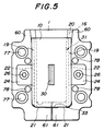
- fitting bores 13, 14 and 15 for detachably receiving a movable cassette plate 10, an ejector cassette plate 11 and one or more ejector pins 12 disposed between the plates 10 and 11.
- the fitting bores 13 to 15 have upper openings 16, 17 and 18 and are shaped in the form of a substantially U as a whole.
- the movable die plate 3 connected to the movable retaining plate 2 through the spacer blocks 4 has a parting face (3A) at the front thereof.
- the fitting bore 13 on the parting face (3A) side in the movable die plate 3 is wider than the fitting bore 14 on the spacer block (4) side.
- the rear surface 20 of the bore 13 are formed in a stepped state.
- the projecting members 22 are formed on a pressing seat member 24 which is fitted into dents 23 formed in the parting face and the inner lateral surface of the fitting bore 13. It is preferable that rear surfaces 25 of the projecting members 22 should be slantingly formed.
- Each pressure seat member 24 is located in the substantially middle portion between the upper end and the bottom of the fitting bore 13.
- the members 24 is detachably fixed onto the rear surfaces 25 of the dents 23 by bolts 26 in such a state that they are biased forward by springs 27.
- the fitting bore 15 formed in the ejector plate 6 is defined by a restraining structure comprising hook members 28 for retaining in position the ejector cassette plate 11 to be set inside the bore 15.
- the spacer blocks 4 are opposed to each other to form an upper opening.
- the aforementioned movable cassette plate 10 has a moulding core face 30 and is provided in the both side surfaces thereof with grooves 31 so as to come in engagement with the projecting members 22 formed on the inner lateral surfaces of the fitting bore 13.
- a rear surface 32 of the groove 31 is formed slantingly in conformity with the slant rear surface 22 of the pressure seat member 24.
- the movable cassette plate 10 is integrated with the ejector cassette plate 11 and the ejector pins 12 extending forward from the ejector cassette plate 11.
- the combined movable cassette plate 10, ejector cassette plate 11, and ejector pins 12 can readily be set in position in the fitting bores 16, 17, 18 only by being placed in the upper openings of the bores 16 - 18.
- the ejector pins 12 are apart from the inner surfaces of the bore 14 and the spacer blocks 4.
- a stationary cassette plate 52 can be exchanged.
- the stationary die plate 9 for retaining the stationry cassette plate 52 is provided with a fitting bore 40 having an upper opening 41.
- pressure seat members 43 which are embeded in dents 44 formed in opposite inner lateral walls 48 and provided on their opposite inner surfaces with projecting members 42.
- the pressure seat member 43 in the dent 44 is fixed by a bolt 46.
- the projecting member 42 on the pressure seat member 43 may be provided with an inclined face 45.
- reference numeral 48 denotes an innermost wall surface, 50 a bottom surface, and 51 springs.
- the stationary cassette plate 52 to be held in the fitting bore 40 of the stationary die plate 9 is formed in a substantially rectangular shape and provided in the side edge surfaces with vertical grooves 53.
- the stationary cassette plate 52 is inserted into the fitting bore 40 through the upper opening 41, it is guided by the projecting members 42 which is in engagement with the grooves 53.
- the stationary cassette plate 52 can readily be set in position into the fitting bore 40 of the stationary die plate 9.
- reference numeral 54 denotes an inclined surface of the groove 53, 55 a moulding cavity, and 56 a lower surface of the stationary die plate 52.
- the movable cassette plate 10 which is placed within the bore 13 is elastically retained there without wobbling and can be readily removed from the movable die plate 3. Besides, the movable cassette plate 10 can be firmly fixed in the bore 13 by tightening the bolts 26 as required. Since the rear surfaces 25 and 32 of the projecting members 22 and the grooves 31 are slantingly formed, the engaging force produced between the opposed rear surfaces 25 and 32 can be adjusted by controlling the bolts 26. Namely, the retaining condition of the movable cassette plate 10 in the bore 13 can be freely changed.
- the movable die plate comprises a pair of die plate halves 60 each formed in the shape of a substantially L. Bottom portions 61 of the die plate halves 60 are small in projected area viewed from the front.
- An ejector plate 62 is provided in the four corner portions thereof with receiving grooves 63 which open forward.
- the depth of the groove 63 is half or less as large as the thickness of the ejector plate 62.
- Each groove 63 is provided on the front portion thereof with a catch member 64.
- a trap groove 15 with stepped lug members 71 for preventing an engaging member 75 in a state inserted into the groove 15 from being out of place.
- the engaging members 75 are disposed on the rear surface of the movable die plate 72 and each comprise a shank 73 and a head 74.
- reference numeral 76 denotes a fitting bore defined between the spacer blocks 4, and 77 a guide pin.
- the cassette die constituted by the elements noted above is assembled in the following manner.
- the flange portions 67 of the return pins 66 are brought into engagement with the receiving grooves 63 of the ejector plate 62, the flange portions 67 are trapped by the catch members 64 to thereby preventing the return pins 66 from moving in the axial direction thereof.
- the shank potions 68 of the return pins 66 are rest on the catch members 64.
- the ejector plate 62 and the movable die plate 72 are united with each other.
- the die plate halves 60 constituting the movable die plate are united to the ejector plate 62 by allowing the return pins 66 extending forward from the ejector plate 62 to be inserted into the through holes 78 bored in the die plate halves 78. Then, the die plate halves 60 which are opposite to each other to form a substantial U-shaped configuration are fixed to the movable retaining plate 2 through the spacer blocks 4.
- the movable cassette plate 10 is fitted into the fitting bore 13 in the manner described early. That is, the engaging member 75 disposed on the movable cassette plate 10 is put into the trap groove 15. Since the head 27 of the engaging member 75 is held by the stepped lug members 71, the cassette plate 10 is in no way released forwardly from the ejector plate 62.
- the width of the space between the die plate halves 60 can be adjusted to meet that of each of the movable cassette plates 10 having different sizes.
- the stationary die plate 9 may also be divided in two.
- the movable-side cassette die comprising the combined movable cassette plate, ejector plate and ejector pins disposed between the plates can be detachably inserted into the fitting bore in the movable die plate through the upper opening of the bore. Consequently, the movable-side cassette die can be easily set in the movable die plate as the die is in the opening state. Accordingly, the cassette die can be speedily fitted in and removed from the die plate.
Landscapes
- Engineering & Computer Science (AREA)
- Mechanical Engineering (AREA)
- Manufacturing & Machinery (AREA)
- Moulds For Moulding Plastics Or The Like (AREA)
Claims (6)
- Matrice de moulage de type cassette (1) pour mouler des résines, comprenant une paire de plateaux matrices mobiles l'un par rapport à l'autre (3,9) ayant chacun un alésage de montage ayant sensiblement la forme d'un U (13,40) qui présente une ouverture supérieure (16,41) et est défini par des surfaces intérieures latérales de chaque plateau matrice (3,9), et une matrice de type cassette respective (10,52) qui peut être insérée de façon amovible dans chacun desdits alésages de montage desdits premiers plateaux matrices (3,9), caractérisée en ce qu'un premier plateau matrice stationnaire (9) présente des éléments récepteurs de pression (43) respectivement intégrés auxdites surfaces intérieures latérales dudit plateau matrice stationnaire (9), chaque élément récepteur ayant une protubérance (42) faisant saillie vers l'intérieur dudit alésage de montage en forme de U (40) dans le plateau matrice stationnaire (9), une surface réceptrice de pression associée de la matrice de type cassette, du côté stationnaire (52), étant en contact avec, et guidée par, lesdites protubérances (42) sur les éléments récepteurs de pression (43), lorsqu'elle est montée dans l'alésage de montage (40) et retenue dans celui-ci par lesdits éléments récepteurs de pression (43); et en ce que le second plateau mobile (3) présente des éléments récepteurs de pression (24) intégrés auxdites surfaces intérieures latérales du plateau matrice mobile (3), chaque élément récepteur de pression (24) ayant une protubérance (22) faisant saillie vers l'intérieur de l'alésage de montage (13) dans le plateau matrice mobile (3); et une paire de blocs écarteurs (4) définissant un alésage (15) communiquant avec ledit alésage de montage (13) dans le plateau matrice mobile (3), des plateaux éjecteurs (6) étant situés dans ledit alésage (15) défini par lesdits blocs écarteurs (4), pour recevoir un plateau cassette éjecteur (11) ayant une ou plusieurs broches d'éjection (12) partant de celui-ci, ladite matrice de type cassette (10), du côté mobile, étant reliée de façon coulissante audit plateau cassette à plateau éjecteur (11), au moyen desdites broches d'éjection (12) et pouvant être insérée de façon amovible dans ledit alésage de montage (13) dudit plateau matrice mobile (3), les surfaces réceptrices de pression associées de la matrice de type cassette (10), du côté mobile, étant sollicitées et guidées par lesdites protubérances (22) desdits éléments récepteurs de pression (24) qui maintiennent la matrice de type cassette (10) dans l'alésage de montage (13).
- Matrice de moulage de type cassette selon la revendication 1, dans laquelle les éléments récepteurs de pression (24,43) sont sollicités de façon élastique et comportent des éléments de réglage ajustables (26) pour modifier la force de pression s'exerçant sur les protubérances (22,42) se trouvant sur les surfaces réceptrices de pression associées des matrices de type cassette respectives (10,52).
- Matrice de moulage de type cassette selon la revendication 2, dans laquelle lesdites surfaces inférieures (25,45) desdites protubérances (22,42) et lesdites surfaces associées (32,54) des matrices de type cassette respectives (10,52) sont des surfaces inclinées pour faciliter l'ajustement de la force de pression s'exerçant entre elles.
- Matrice de moulage de type cassette selon l'une quelconque des revendications 1-3, dans laquelle lesdites matrices de type cassette (10,52) sont chacune munies dans leurs surfaces latérales, de gorges (31,53) qui s'engagent sur les protubérances respectives (22,42) lorsque lesdites matrices de type cassette sont respectivement insérées dans lesdits plateaux matrices (3,9).
- Matrice de moulage de type cassette selon l'une quelconque des revendications 1-4, lesdits alésages (13,15) dudit plateau matrice mobile (3) communiquant au travers d'un alésage supplémentaire (14) et ledit alésage de montage (13), du côté de la face de séparation (3A) du plateau matrice (3), étant plus large que ledit alésage supplémentaire (14) se trouvant du côté des blocs écarteurs (4) du plateau matrice (3).
- Matrice de moulage de type cassette selon l'une quelconque des revendications 1-5, dans laquelle ledit plateau matrice mobile (3) est divisé, dans sa partie inférieure (61), en deux moitiés (60) ayant sensiblement la forme d'un L.
Applications Claiming Priority (4)
| Application Number | Priority Date | Filing Date | Title |
|---|---|---|---|
| JP1987056632U JPH0514828Y2 (fr) | 1987-04-16 | 1987-04-16 | |
| JP56632/87U | 1987-04-16 | ||
| JP1987125022U JPH054978Y2 (fr) | 1987-08-17 | 1987-08-17 | |
| JP125022/87U | 1987-08-17 |
Publications (3)
| Publication Number | Publication Date |
|---|---|
| EP0287203A2 EP0287203A2 (fr) | 1988-10-19 |
| EP0287203A3 EP0287203A3 (en) | 1990-02-28 |
| EP0287203B1 true EP0287203B1 (fr) | 1994-05-04 |
Family
ID=26397589
Family Applications (1)
| Application Number | Title | Priority Date | Filing Date |
|---|---|---|---|
| EP88301539A Expired - Lifetime EP0287203B1 (fr) | 1987-04-16 | 1988-02-23 | Moule en forme de cassette |
Country Status (5)
| Country | Link |
|---|---|
| US (1) | US4861254A (fr) |
| EP (1) | EP0287203B1 (fr) |
| KR (1) | KR900007341B1 (fr) |
| CA (1) | CA1296850C (fr) |
| DE (1) | DE3889378T2 (fr) |
Cited By (6)
| Publication number | Priority date | Publication date | Assignee | Title |
|---|---|---|---|---|
| US4959007A (en) * | 1987-12-04 | 1990-09-25 | Sumitomo Heavy Industries Ltd. | Insert-type rotary core mold apparatus |
| WO1992011123A1 (fr) * | 1990-12-21 | 1992-07-09 | Marianne Wieser | Insert amovible pour moules de coulee et moule de coulee pour la fabrication de pieces moulees |
| EP0479710A3 (en) * | 1990-10-03 | 1992-11-25 | A/S Eccolet Sko | Fully automatic manufacturing machine, preferably for the manufacturing of shoes |
| EP0555567A1 (fr) * | 1992-02-10 | 1993-08-18 | Sankyo Engineering Co. Ltd. | Moule métallique d'injection |
| EP0598169A1 (fr) * | 1992-11-18 | 1994-05-25 | GOBBI GIUSEPPE & C. S.n.c. | Moule d'injection pour la fabrication de nombreuses séries de produits, notamment des boutons et similaires |
| WO2002074513A1 (fr) * | 2001-03-15 | 2002-09-26 | Colin John Woodroffe | Moule d'injection |
Families Citing this family (71)
| Publication number | Priority date | Publication date | Assignee | Title |
|---|---|---|---|---|
| CH676104A5 (fr) * | 1988-09-14 | 1990-12-14 | Bucher Guyer Ag Masch | |
| FI82900C (fi) * | 1989-01-20 | 1991-05-10 | Mauno Montonen | Form. |
| DE3934495C1 (fr) * | 1989-10-16 | 1990-12-13 | Marianne 8780 Gemuenden De Wieser | |
| TW205018B (fr) * | 1990-11-30 | 1993-05-01 | Toshiba Machine Co Ltd | |
| US5302103A (en) * | 1991-10-10 | 1994-04-12 | Gencorp Inc. | Injection molding machine including quick-change mold assembly |
| JPH06824A (ja) * | 1992-06-18 | 1994-01-11 | Fanuc Ltd | 中子突き出し装置 |
| US5350289A (en) * | 1992-07-27 | 1994-09-27 | Master Unit Die Products, Inc. | Quick change system for mold bases |
| US5562935A (en) * | 1992-07-27 | 1996-10-08 | Master Unit Die Products, Inc. | Quick change system for mold bases |
| DE4239776A1 (de) * | 1992-11-26 | 1994-06-01 | Polygram Record Service Gmbh | Spritzgieß- oder Spritzprägemaschine |
| DE4340661C1 (de) * | 1993-11-30 | 1995-08-17 | Armin Spiess | Handhabungssystem für Gießformen |
| US5409364A (en) * | 1993-12-09 | 1995-04-25 | Playskool, Inc. | Extruder assembly for modeling composition |
| DE69827176T2 (de) | 1997-01-31 | 2005-03-17 | Fuji Photo Film Co., Ltd., Minami-Ashigara | Formwerkzeug zum Giessen des Gehäuses einer Magnetbandkassette |
| JPH11238343A (ja) * | 1998-02-20 | 1999-08-31 | Fuji Photo Film Co Ltd | 磁気テープカセット |
| US6325614B1 (en) | 1998-04-24 | 2001-12-04 | Husky Injection Molding | Mold element retaining and releasing mechanism |
| US6196825B1 (en) * | 1998-12-22 | 2001-03-06 | Core Materials, Inc. | Compression molding system, apparatus and method |
| US6328552B1 (en) * | 1999-08-20 | 2001-12-11 | Wbnl Dba Aimmco | Injection molding machine and method |
| US6413074B1 (en) | 1999-09-28 | 2002-07-02 | Composix Corporation | Assembly for molding plastic material |
| AU2741001A (en) * | 1999-12-29 | 2001-07-09 | Security Plastics, Inc. | Injection mold key lock |
| US6422297B2 (en) | 2000-03-15 | 2002-07-23 | Zoltan P. Salata | Interchangeable die for a die casting machine |
| DE10231551A1 (de) * | 2002-07-11 | 2004-01-22 | Balda Werkzeug- Und Vorrichtungsbau Gmbh | Formwerkzeug für Kunststoff-Gehäuseteile |
| US7338626B1 (en) | 2002-12-14 | 2008-03-04 | Federal Mogul World Wide, Inc. | High cavitation, low tonnage rubber mold machine and method |
| US7497677B1 (en) | 2003-09-08 | 2009-03-03 | Crain Enterprises, Inc. | Mold having modular submold |
| US7241405B1 (en) | 2003-09-08 | 2007-07-10 | Crain Enterprises, Inc. | Method of renewing a mold block |
| US7204685B1 (en) | 2003-09-08 | 2007-04-17 | Crain Enterprises, Inc. | Modular mold |
| DE102004019633A1 (de) * | 2004-04-22 | 2005-11-17 | August Läpple GmbH & Co. KG | Vorrichtung zum Herstellen von Spritzguss-Formteilen |
| US20050280189A1 (en) * | 2004-06-22 | 2005-12-22 | The Boeing Company | Undercut For Bushing Retention For SLS Details |
| US20050285314A1 (en) * | 2004-06-28 | 2005-12-29 | The Boeing Company | Integral Nut Slot System In SLS Details |
| US7500843B2 (en) * | 2004-09-08 | 2009-03-10 | Crain Enterprises, Inc. | Mold system kit |
| US20060105076A1 (en) * | 2004-11-17 | 2006-05-18 | Adas James O | Molding apparatus |
| US8025376B2 (en) | 2005-09-29 | 2011-09-27 | Brother Kogyo Kabushiki Kaisha | Ink cartridges |
| US7828421B2 (en) | 2005-09-29 | 2010-11-09 | Brother Kogyo Kabushiki Kaisha | Ink cartridge arrangements |
| US7837311B2 (en) | 2005-09-29 | 2010-11-23 | Brother Kogyo Kabushiki Kaisha | Ink cartridges |
| US7682004B2 (en) | 2005-09-29 | 2010-03-23 | Brother Kogyo Kabushiki Kaisha | Ink cartridges |
| US7553007B2 (en) | 2005-09-29 | 2009-06-30 | Brother Kogyo Kabushiki Kaisha | Ink cartridges |
| US7775645B2 (en) | 2005-09-29 | 2010-08-17 | Brother Kogyo Kabushiki Kaisha | Methods of forming cartridges, such as ink cartridges |
| US7810916B2 (en) | 2005-09-29 | 2010-10-12 | Brother Kogyo Kabushiki Kaisha | Ink cartridges |
| TW200720043A (en) * | 2005-11-25 | 2007-06-01 | Hon Hai Prec Ind Co Ltd | A tool |
| CN101053982B (zh) * | 2006-04-14 | 2010-05-26 | 鸿富锦精密工业(深圳)有限公司 | 模具装置 |
| US7837455B2 (en) * | 2006-07-28 | 2010-11-23 | Ethicon, Inc. | Apparatus and method for making suture packages |
| US20080173786A1 (en) * | 2007-01-23 | 2008-07-24 | Cheng Uei Precision Industry Co., Ltd. | Injection Mold Including a Quick-Change Mold Assembly |
| US20080248151A1 (en) * | 2007-04-05 | 2008-10-09 | Chih-Yu Chen | Cavity insert positioning mechanism of an injection mold |
| US7413427B1 (en) * | 2007-05-07 | 2008-08-19 | Cheng Uei Precision Industry Co., Ltd. | Ejection mechanism |
| US20080308710A1 (en) * | 2007-06-14 | 2008-12-18 | Chen-Chih Yu | Mold with a returning apparatus |
| US7866972B2 (en) * | 2007-10-25 | 2011-01-11 | Kuo Fei-Pin | Replaceable double-plate-injection mold |
| CN101497221B (zh) * | 2008-01-31 | 2012-06-20 | 鸿富锦精密工业(深圳)有限公司 | 模具及其调整方法 |
| US20090205397A1 (en) * | 2008-02-15 | 2009-08-20 | Yates David N | Quick change tool for die casting metal |
| TWI399274B (zh) * | 2008-05-30 | 2013-06-21 | Hon Hai Prec Ind Co Ltd | 鏡片成型模具 |
| US20100129484A1 (en) * | 2008-11-26 | 2010-05-27 | Scott Ansell | Mold system for producing ophthalmic devices |
| CN101927540B (zh) * | 2009-06-24 | 2013-12-11 | 鸿富锦精密工业(深圳)有限公司 | 模具 |
| TWI454363B (zh) * | 2009-06-30 | 2014-10-01 | Hon Hai Prec Ind Co Ltd | 模具 |
| CN101992514B (zh) * | 2009-08-19 | 2013-08-28 | 鸿富锦精密工业(深圳)有限公司 | 导光板成型模具 |
| CN102555113A (zh) * | 2010-12-14 | 2012-07-11 | 任源企业股份有限公司 | 快速换模及通用的成型模具装置 |
| DE102011007995B4 (de) * | 2011-01-04 | 2016-06-23 | Meusburger Georg GmbH & Co. KG | Wechselform für eine Spritzgießmaschine mit optimierter Nutzfläche |
| CN102166812A (zh) * | 2011-01-19 | 2011-08-31 | 大连理工大学 | 一种型芯可插拔式的微注塑模具 |
| TWI495554B (zh) * | 2011-07-04 | 2015-08-11 | Jen Yuan Plastics Co Ltd | 共用模座之小水口模具組 |
| DE102011055961A1 (de) * | 2011-12-02 | 2013-06-06 | B & R GmbH | Spritzgussvorrichtung zum Spritzgießen von Kunststoffmaterialien |
| TW201323181A (zh) * | 2011-12-08 | 2013-06-16 | Hon Hai Prec Ind Co Ltd | 成型模具 |
| TW201325864A (zh) * | 2011-12-23 | 2013-07-01 | Hon Hai Prec Ind Co Ltd | 射出成型模具 |
| DE102013002012A1 (de) * | 2013-02-06 | 2014-08-07 | Jürgen Stumpf | Verfahren zur Herstellung von individuell angepassten Schuheinlagen |
| US9205586B2 (en) * | 2013-05-03 | 2015-12-08 | The Hc Companies, Inc. | Hybrid injection molding system |
| WO2015008110A1 (fr) * | 2013-07-17 | 2015-01-22 | Selle Royal S.P.A. | Dispositif et procédé de fabrication d'un support pour le corps humain |
| DK201470307A (da) * | 2014-05-28 | 2014-05-28 | Lego As | Formværktøj til sprøjtestøbning |
| CN106182511B (zh) * | 2015-05-07 | 2018-11-06 | 苏州汉扬精密电子有限公司 | 模具的斜销结构 |
| US10350801B2 (en) * | 2015-11-25 | 2019-07-16 | Taiga Coolers, LLC | System and method for production of customized food and beverage coolers |
| KR101956573B1 (ko) * | 2017-12-31 | 2019-03-11 | (주)금경테크 | 수지성형용 카세트형 금형 |
| CN110405177B (zh) * | 2018-04-26 | 2021-01-26 | Ykk株式会社 | 压铸装置 |
| KR102171537B1 (ko) | 2018-06-21 | 2020-10-29 | 지오네이션 주식회사 | 급가열 및 급냉각이 가능한 몰드를 이용한 수지 이송 성형방법 |
| JP6460507B1 (ja) * | 2018-07-31 | 2019-01-30 | ニチエツ株式会社 | 射出成形機の金型搬送ガイド装置 |
| CN111515363A (zh) * | 2019-02-01 | 2020-08-11 | 苏州汉扬精密电子有限公司 | 压铸模具的顶出结构 |
| CN113524590A (zh) * | 2021-07-22 | 2021-10-22 | 顺德职业技术学院 | 一种设有导向顶出抽芯机构的车载冰箱模具 |
| US20250340000A1 (en) * | 2024-05-06 | 2025-11-06 | Progressive Components International Corporation | Gate insert for injection molding |
Citations (1)
| Publication number | Priority date | Publication date | Assignee | Title |
|---|---|---|---|---|
| US3647309A (en) * | 1969-09-19 | 1972-03-07 | Dorn Co V | Apparatus for controlling an injection molding machine |
Family Cites Families (5)
| Publication number | Priority date | Publication date | Assignee | Title |
|---|---|---|---|---|
| US4202522A (en) * | 1977-06-16 | 1980-05-13 | Honeywell Inc. | Injection molding apparatus for accommodating various sizes of molding die inserts |
| JPS576738A (en) * | 1980-06-16 | 1982-01-13 | Sanko Raito Kogyo Kk | Cassette mold for injection molding |
| JPS59174331A (ja) * | 1983-03-23 | 1984-10-02 | Sumitomo Heavy Ind Ltd | 入子交換装置を備えた射出成形機 |
| JPS60116420A (ja) * | 1983-11-30 | 1985-06-22 | Hitachi Ltd | 成形用金型 |
| JPH06153213A (ja) * | 1992-10-29 | 1994-05-31 | Totoku Electric Co Ltd | 陰極線管の消磁コイル |
-
1987
- 1987-11-11 KR KR1019870012697A patent/KR900007341B1/ko not_active Expired
-
1988
- 1988-02-23 DE DE3889378T patent/DE3889378T2/de not_active Expired - Fee Related
- 1988-02-23 EP EP88301539A patent/EP0287203B1/fr not_active Expired - Lifetime
- 1988-03-02 US US07/163,113 patent/US4861254A/en not_active Expired - Lifetime
- 1988-04-14 CA CA000564211A patent/CA1296850C/fr not_active Expired - Lifetime
Patent Citations (1)
| Publication number | Priority date | Publication date | Assignee | Title |
|---|---|---|---|---|
| US3647309A (en) * | 1969-09-19 | 1972-03-07 | Dorn Co V | Apparatus for controlling an injection molding machine |
Cited By (7)
| Publication number | Priority date | Publication date | Assignee | Title |
|---|---|---|---|---|
| US4959007A (en) * | 1987-12-04 | 1990-09-25 | Sumitomo Heavy Industries Ltd. | Insert-type rotary core mold apparatus |
| EP0395805A1 (fr) * | 1987-12-04 | 1990-11-07 | Sumitomo Heavy Industries, Ltd | Dispositif de moulage à noyau rotatif du type à insert |
| EP0479710A3 (en) * | 1990-10-03 | 1992-11-25 | A/S Eccolet Sko | Fully automatic manufacturing machine, preferably for the manufacturing of shoes |
| WO1992011123A1 (fr) * | 1990-12-21 | 1992-07-09 | Marianne Wieser | Insert amovible pour moules de coulee et moule de coulee pour la fabrication de pieces moulees |
| EP0555567A1 (fr) * | 1992-02-10 | 1993-08-18 | Sankyo Engineering Co. Ltd. | Moule métallique d'injection |
| EP0598169A1 (fr) * | 1992-11-18 | 1994-05-25 | GOBBI GIUSEPPE & C. S.n.c. | Moule d'injection pour la fabrication de nombreuses séries de produits, notamment des boutons et similaires |
| WO2002074513A1 (fr) * | 2001-03-15 | 2002-09-26 | Colin John Woodroffe | Moule d'injection |
Also Published As
| Publication number | Publication date |
|---|---|
| KR900007341B1 (ko) | 1990-10-08 |
| EP0287203A3 (en) | 1990-02-28 |
| DE3889378T2 (de) | 1995-02-09 |
| CA1296850C (fr) | 1992-03-10 |
| US4861254A (en) | 1989-08-29 |
| EP0287203A2 (fr) | 1988-10-19 |
| DE3889378D1 (de) | 1994-06-09 |
| KR880012330A (ko) | 1988-11-26 |
Similar Documents
| Publication | Publication Date | Title |
|---|---|---|
| EP0287203B1 (fr) | Moule en forme de cassette | |
| EP0498102B1 (fr) | Appareil de démoulage universel | |
| US6039558A (en) | Mold for injection molding of a plastic product | |
| CN108943608B (zh) | 模具及其开模方法 | |
| EP2261000A1 (fr) | Dispositif de démoulage de négatifs à injection plastique | |
| JP3358487B2 (ja) | 樹脂成形用金型装置 | |
| JP3848581B2 (ja) | 射出成形機用金型 | |
| JPH01128811A (ja) | 成形装置の型交換機構 | |
| JPH11514596A (ja) | 射出成形装置用の成形型薄板組立体 | |
| EP0669194A1 (fr) | Procédé et dispositif pour le moulage d'un produit comprenant un insert | |
| US6416316B1 (en) | Apparatus for molding resin products | |
| CN216579026U (zh) | 一种前保险杠装饰板后模内滑块抽芯注塑模具 | |
| JP3168378B2 (ja) | カセット式射出成形金型装置 | |
| JPS6338072Y2 (fr) | ||
| CN210911000U (zh) | 侧抽芯机构 | |
| JPH0711952Y2 (ja) | 樹脂成形用カセット式金型の押え部材 | |
| CA1230462A (fr) | Parois laterales pour moules de coulee en continu | |
| JPH0536649Y2 (fr) | ||
| CN216912045U (zh) | 一种高效成型的一出二电机外壳压铸模具 | |
| JP3168379B2 (ja) | カセット式射出成形金型装置 | |
| JP3158337B2 (ja) | 樹脂シャッタの成形金型および成形方法 | |
| CN112829224A (zh) | 一种带有倾斜手柄的注塑产品的注塑模具和注塑方法 | |
| JP3036332B2 (ja) | サンドイッチ成形用の金型装置 | |
| JPH0736729Y2 (ja) | カセット式の樹脂成形用金型 | |
| JPH0514828Y2 (fr) |
Legal Events
| Date | Code | Title | Description |
|---|---|---|---|
| PUAI | Public reference made under article 153(3) epc to a published international application that has entered the european phase |
Free format text: ORIGINAL CODE: 0009012 |
|
| AK | Designated contracting states |
Kind code of ref document: A2 Designated state(s): BE CH DE FR GB IT LI |
|
| PUAL | Search report despatched |
Free format text: ORIGINAL CODE: 0009013 |
|
| AK | Designated contracting states |
Kind code of ref document: A3 Designated state(s): BE CH DE FR GB IT LI |
|
| 17P | Request for examination filed |
Effective date: 19900807 |
|
| 17Q | First examination report despatched |
Effective date: 19910416 |
|
| GRAA | (expected) grant |
Free format text: ORIGINAL CODE: 0009210 |
|
| AK | Designated contracting states |
Kind code of ref document: B1 Designated state(s): BE CH DE FR GB IT LI |
|
| REF | Corresponds to: |
Ref document number: 3889378 Country of ref document: DE Date of ref document: 19940609 |
|
| ITF | It: translation for a ep patent filed | ||
| ET | Fr: translation filed | ||
| PLBE | No opposition filed within time limit |
Free format text: ORIGINAL CODE: 0009261 |
|
| STAA | Information on the status of an ep patent application or granted ep patent |
Free format text: STATUS: NO OPPOSITION FILED WITHIN TIME LIMIT |
|
| 26N | No opposition filed | ||
| PGFP | Annual fee paid to national office [announced via postgrant information from national office to epo] |
Ref country code: GB Payment date: 19960209 Year of fee payment: 9 Ref country code: BE Payment date: 19960209 Year of fee payment: 9 |
|
| PGFP | Annual fee paid to national office [announced via postgrant information from national office to epo] |
Ref country code: CH Payment date: 19960226 Year of fee payment: 9 |
|
| PGFP | Annual fee paid to national office [announced via postgrant information from national office to epo] |
Ref country code: DE Payment date: 19960227 Year of fee payment: 9 |
|
| PGFP | Annual fee paid to national office [announced via postgrant information from national office to epo] |
Ref country code: FR Payment date: 19960229 Year of fee payment: 9 |
|
| PG25 | Lapsed in a contracting state [announced via postgrant information from national office to epo] |
Ref country code: GB Effective date: 19970223 |
|
| PG25 | Lapsed in a contracting state [announced via postgrant information from national office to epo] |
Ref country code: LI Effective date: 19970228 Ref country code: CH Effective date: 19970228 Ref country code: BE Effective date: 19970228 |
|
| BERE | Be: lapsed |
Owner name: SHINKOH SELLBIC CO. LTD Effective date: 19970228 |
|
| GBPC | Gb: european patent ceased through non-payment of renewal fee |
Effective date: 19970223 |
|
| REG | Reference to a national code |
Ref country code: CH Ref legal event code: PL |
|
| PG25 | Lapsed in a contracting state [announced via postgrant information from national office to epo] |
Ref country code: FR Effective date: 19971030 |
|
| PG25 | Lapsed in a contracting state [announced via postgrant information from national office to epo] |
Ref country code: DE Effective date: 19971101 |
|
| REG | Reference to a national code |
Ref country code: FR Ref legal event code: ST |
|
| PG25 | Lapsed in a contracting state [announced via postgrant information from national office to epo] |
Ref country code: IT Free format text: LAPSE BECAUSE OF NON-PAYMENT OF DUE FEES;WARNING: LAPSES OF ITALIAN PATENTS WITH EFFECTIVE DATE BEFORE 2007 MAY HAVE OCCURRED AT ANY TIME BEFORE 2007. THE CORRECT EFFECTIVE DATE MAY BE DIFFERENT FROM THE ONE RECORDED. Effective date: 20050223 |