EP0287225B1 - Einführungsvorrichtung für eine optische Faser - Google Patents
Einführungsvorrichtung für eine optische Faser Download PDFInfo
- Publication number
- EP0287225B1 EP0287225B1 EP88302553A EP88302553A EP0287225B1 EP 0287225 B1 EP0287225 B1 EP 0287225B1 EP 88302553 A EP88302553 A EP 88302553A EP 88302553 A EP88302553 A EP 88302553A EP 0287225 B1 EP0287225 B1 EP 0287225B1
- Authority
- EP
- European Patent Office
- Prior art keywords
- transmission line
- duct
- fluid
- inlet
- outlet
- Prior art date
- Legal status (The legal status is an assumption and is not a legal conclusion. Google has not performed a legal analysis and makes no representation as to the accuracy of the status listed.)
- Expired - Lifetime
Links
Images

Classifications
-
- G—PHYSICS
- G02—OPTICS
- G02B—OPTICAL ELEMENTS, SYSTEMS OR APPARATUS
- G02B6/00—Light guides; Structural details of arrangements comprising light guides and other optical elements, e.g. couplings
- G02B6/46—Processes or apparatus adapted for installing or repairing optical fibres or optical cables
- G02B6/50—Underground or underwater installation; Installation through tubing, conduits or ducts
- G02B6/52—Underground or underwater installation; Installation through tubing, conduits or ducts using fluid, e.g. air
Definitions
- This invention relates to transmission lines and to the introduction of a transmission line into a duct through which it is to be advanced by fluid drag.
- Our European Patent 108590 discloses a method and apparatus for installation of transmission lines within tubular ducts using fluid drag to advance the transmission line along the duct.
- compressed gas is used to provide the fluid drag and an optical fibre transmission line package is introduced via a feed head and feed wheels are provided to urge the fibre package into the duct against the hydrostatic potential that is experienced.
- a further problem that arises with positive pressure feed heads is the provision of a seal to inhibit backflow of fluid between the inlet tube for the fibre package and the fibre package itself. It is necessary for the fibre to be able to advance without being over-tensioned, but at the same time the greater than atmospheric pressure within the feed head needs to be maintained. Sealing may be particularly difficult to achieve because there can be a considerable variation in cross-sectional shape and diameter of some transmission line packages, for example the tolerance on the diameter of multifibre package may be as much as ⁇ 10% Thus if a very closely fitting collet is located around the fibre package the positive deviations in diameter may result in the package being gripped too tightly, resulting in excessive tension on the optical fibre. In practice an inefficient sealing arrangement of a collet of greater diameter than the package and sufficient to accommodate the package cross sectional variation is used, and this results in fluid propellant leakages as high as 50% occurring between the fibre and collet.
- the apparatus is intended for the processing of thin wire for memory applications.
- the apparatus consists of a plurality of liquid-treatment cells, the wire being advanced through the line of cells by virtue of the viscous fluid drag within nozzle portions. A different treatment is provided in each treatment cell, carry over of the fluids used for treatment being prevented by means of gas separating chambers located between adjacent fluid treatment zones. It is nowhere suggested in this document that a wire can be installed in a line such as that shown using viscous fluid drag. It appears rather that it would be necessary to thread the wire carefully through the line before using the described viscous drag process to advance the already installed wire through the line.
- the present invention is directed towards installing and advancing transmission lines in installation passageways, to reduce or eliminate the need for mechanical advancement, and/or to achieving greater installation distances.
- the present invention provides apparatus for installing a transmission line in an installation duct by means of viscous drag of a fluid, so that the transmission line extends between a transmission line inlet to the duct and a transmission line outlet of the duct remote from the inlet, the apparatus comprising fluid inlet means for admitting fluid to the duct at sufficient pressure to advance the transmission line along the duct, and an outlet for the fluid and transmission line for connection to the installation duct, wherein a further fluid outlet means from the tubular passageway is provided downstream from the fluid inlet means.
- the present invention provides apparatus for installing a transmission line in an installation duct by means of viscous drag of a fluid, so that the transmission line extends between a transmission line inlet to the duct and a transmission line outlet of the duct remote from the inlet, the apparatus comprising the installation duct and fluid inlet means for admitting fluid to advance the transmission line along the duct, characterised in that a fluid outlet means is provided downstream from the fluid inlet means but a substantial distance upstream of the transmission line outlet.
- the present invention provides apparatus for installing a transmission line in an installation duct substantially longer than 3 metres by means of viscous drag of a fluid, so that the transmission line extends between a transmission line inlet to the duct and a transmission line outlet remote from the inlet, the apparatus comprising: a tubular passageway substantially shorter than said installation duct, for example 3 metres or less in length, and having a transmission line inlet end and a transmission line outlet end for connection to the transmission line inlet of the installation duct; and fluid inlet means for admitting fluid to the passageway; wherein a fluid outlet means is disposed between said fluid inlet means and said transmission line outlet end of the passageway; and wherein a closed unit holding a supply of transmission line is provided, the transmission line inlet of the passageway being sealed to the unit from whence the transmission line may be paid out.
- the present invention provides apparatus for installing a transmission line in an installation duct substantially longer than 3 metres by means of viscous drag of a fluid, so that the transmission line extends between a transmission line inlet to the duct and a transmission line outlet remote from the inlet, the apparatus comprising: a tubular passageway substantially shorter than said installation duct, for example 3 metres or less in length, and having a transmission line inlet end and a transmission line outlet end for connection to said transmission line inlet of the installation duct; fluid inlet means for admitting fluid to the passageway; and means for inhibiting backflow of fluid medium towards the transmission line inlet end of the passageway; wherein a fluid outlet means is disposed between said fluid inlet means and said transmission line outlet end of the passageway.
- the present invention provides a method of installing a transmission line in a tubular duct by means of viscous drag of a fluid, so that the transmission line extends between a transmission line inlet to the duct and a transmission line outlet remote from the inlet, the method comprising admitting fluid at an upstream end of the duct to advance the transmission line along the duct from the inlet towards the outlet, wherein some of the fluid from the duct is discharged at a location intermediate the inlet and outlet during at least part of the installation process, the discharge location being a short distance, compared to the overall length of the duct, from the transmission line inlet, and whereby the transmission line continues to advance along the duct to the outlet by means of viscous fluid drag forces acting thereon in the passageway downstream of said location.
- transmission line 'package' should be interpreted to mean any transmission line adapted for or suitable for installation by fluid drag techniques, and mav for example comprise a simple transmission line, transmission lines comprising at least one optical fibre, or transmission lines having a lightweight or foamed covering for the purpose of increasing surface area to mass ratio. Such a covering may also provide suitable drag and friction characteristics and ruggedisation of the transmission line.
- 'Installation duct' or 'installation passageway' refers to the routes along which transmission lines are installed, such routes may for example be within buildings or over or underground, and frequently contain bends.
- a tubular duct 1 is provided with a fluid inlet 2, which may be for gas or liquid but it is especially preferred to utilise compressed air and is described hereinafter in that context, a bleed valve 3 and a seal.
- the inlet 2 is located close to the end of the duct to which a transmission line package such as an optical fibre package 5 is input, and the seal 4 has a passage for the fibre package 5 and seals against the duct 1 and the fibre package 5.
- the bleed valve is located a short distance (compared with the overall length of duct) from the fibre input end, typically 0.5 to 3 metres from the input end.
- the fibre package In order to commence the installation operation, referred to as the blowing operation, the fibre package is threaded through the seal, urged a short way into the duct and then compressed air is introduced via the inlet.
- compressed air With fibre blowing systems it is generally necessary to urge the fibre package into the duct against hydrostatic potential created by introduction of compressed air until the package is inserted along about one third of the length of the duct, after which the fibre is propelled by viscous drag. Previously the fibre package has been pushed for this first one third of the duct by motor driven wheels.
- compressed air (typically at a pressure of about 1000KPa (10 bar) is introduced at the inlet, but instead of all the air progressing completely through the duct a proportion (for example up to 80%) is bled off through the bleed valve to create a high local flow between the fibre input and the bleed valve.
- This high local flow produces sufficient driving force to push the fibre along the first third of the duct against the hydrostatic potential.
- the bleed valve is adjustable and the proportion of air bled through the valve is reduced as the fibre package progresses along the first third of the duct.
- a control means may be included which senses tension or buckling of the fibre package, and this control may be linked to increase or decrease the level of discharge through the bleed valve.
- the length of duct between the fibre input and the bleed valve may be regarded as a short duct connected directly to a longer duct, and it is envisaged that the duct prior to the bleed valve need not be integral with the main part of the duct after the bleed valve. It will be realised that the blown feed-in may be applied directly to the end of an installed duct, this being achieved either by tapping into the duct to provide the compressed air inlet and bleed valve or by attaching a length of ducting provided with an air inlet and bleed valve.
- An alternative embodiment of the invention is for a vent to be located a substantial distance along the duct, for example at the mid point or two thirds of the way along, and for air to be bled from that vent until the transmission line has approached close to it, at which time the vent is then closed.
- a vent may be considered a 'temporary termination' of the duct.
- a series of vents that are sequentially opened and closed as the transmission line advances may also be provided. Optimally this is used in conjunction with a blown feed-in, but may be utilised with other feed-in mechanisms to improve continuous installation lengths.
- the flow rate of the air may be increased by employing suction at vent locations, or additional air may be injected into the duct at intermediate locations (i.e. other than at the end) along the duct, preferably with an associated subsequent vent.
- FIG 2 illustrates in more detail the seal 4 through which the fibre package is threaded.
- This seal enables the fibre package to be introduced from an open source such as a reel or pan of fibre package.
- the seal 4 is substantially cylindrical and has a central bore 6 through which the fibre 5 is threaded. For most of its length the bore 6 is of greater diameter than the fibre 5 so that the fibre can pass freely through the bore.
- the bore of the seal tapers to closely match the diameter of the fibre 5 and the wall thickness of the seal also tapers to form a lip portion 7 closely surrounding the fibre 5.
- Suitable plastics include Hyperlast 2851/106, a polyurethane elastomer supplied by B and T Polymers and PVCs such as VX329 made by British Plastics Industry Ltd.
- VX types of PVC and Alkathene made by ICI may also be used, but presently VX329 is preferred for its performance and the simplicity of injection moulding which is possible for PVC.
- Cold setting materials are not as convenient for large scale production although suitable final properties may be obtained.
- the optimum shape for the lips of the seal is for the internal bore to be tapered so that the tip of the lips nearly or just contact the fibre package: it is possible for there to be 5 virtually no contact in the absence of pressure.
- the outer surface of the lips (which face inwardly of a feed head) are tapered such that at the point of contact the material is very thin. This provides sufficient flexibility to enable the pressure inside the head to urge the lips into sealing contact. In order to avoid inversion the angle of taper is large to retain strength against inversion.
- BPI VX329 grade PVC provides a suitable seal when the minimum inside diameter of the lip portion of the seal is 2mm and the outer diameter of the lip portion is 2.9mm.
- This seal operates well in the range of 300 to 1300KPa.
- a seal of similar material and outer dimensions but lesser internal diameter, eg 1.6mm for 1.6mm packages, is also satisfactory.
- the seal may be made of softer material, for example for a single fibre package, and this may be complemented by using a lower air pressure.
- seals may also be used for other applications where a moving fibre unit or package needs to be sealed across a pressure differential.
- seal may be incorporated into other types of feedheads for fibre blowing to reduce leakage.
- Multi bore or manifold seals may also be provided for multiple installations.
- the apparatus and method described herein may be used for installation of transmission lines other than the described optical fibre packages and in some instances a special packaging may not be required.
- the transmission line may comprise metallic conductors or metallic conductors may be included in an optical fibre package for fluid drag installation.
- a plurality of transmission lines may be installed in a single duct, either sequentially or in the same blowing operation.
- Pulsed fluid input and/or pulsed venting may be utilised; in particular pulsed venting, with the pulse rate controlled to increase or decrease the degree of venting, may be utilised in an automaticaly controlled system, for example with an electrically pulsed bleed valve.
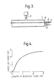
- the fibre may be introduced to the duct via a closely fitting tube 8 attached to an end plate 9 as shown in Figure 3.
- fibre packages exhibit a varying degree of 'blowability', that is some nominally similar packages achieve greater installation distances under the same blowing conditions than other packages.
- a technique for measuring the blowability is for the fibre to be blown along a short duct and for a retarding force to be applied, the force registered for a given blowing strength or the blowing strength required for a given force being measured to indicate blowability.
- Such a system may be incorporated on a production line to grade or quality conrol the package.
- the apparatus for this test may comprise a blow and vent arangement, although the vent may be constituted by the end of the tube. Similar testing may be applied using a liquid fluid medium.
Landscapes
- Physics & Mathematics (AREA)
- General Physics & Mathematics (AREA)
- Optics & Photonics (AREA)
- Light Guides In General And Applications Therefor (AREA)
- Electric Cable Installation (AREA)
- Mechanical Coupling Of Light Guides (AREA)
- Laser Surgery Devices (AREA)
- Surface Treatment Of Glass Fibres Or Filaments (AREA)
- Endoscopes (AREA)
- Transition And Organic Metals Composition Catalysts For Addition Polymerization (AREA)
- Pipeline Systems (AREA)
Claims (27)
- Vorrichtung zur Verlegung einer Übertragungsleitung (5) in einem Verlegungskanal (1) durch den Mitspüleffekt eines Fluids, so daß sich die Übertragungsleitung zwischen einem Einlaß in den Kanal (1) für die Übertragungsleitung und einem vom Einlaß entfernten Übertragungsleitungsauslaß des Kanals erstreckt, wobei die Vorrichtung einen rohrförmigen Weg umfaßt, der eine Fluid-Einlaßvorrichtung (2) zur Zuleitung von Fluid in den Kanal unter einem ausreichenden Druck aufweist, um die Übertragungsleitung im Kanal vorwärtszubewegen, und einen Auslaß für das Fluid und die Übertragungsleitung zur Verbindung mit dem Verlegungskanal (1),
dadurch gekennzeichnet,
daß eine weitere Fluid-Auslaßvorrichtung (3) aus dem rohrförmigen Weg stromab von der Fluid-Einlaßvorrichtung (2) vorgesehen ist. - Vorrichtung zur Verlegung einer Übertragungsleitung (5) in einem Verlegungskanal (1) durch den Mitspüleffekt eines Fluids, so daß sich die Übertragungsleitung zwischen einem Einlaß in den Kanal (1) für die Übertragungsleitung und einem vom Einlaß entfernten Übertragungsleitungsauslaß des Kanals erstreckt, wobei die Vorrichtung den Verlegungskanal (1) und eine Fluid-Einlaßvorrichtung (2) zur Zuleitung von Fluid zur Vorwärtsbewegung der Übertragungsleitung im Kanal umfaßt,
dadurch gekennzeichnet,
daß eine Fluid-Auslaßvorrichtung (3) stromab von der Fluid-Einlaßvorrichtung, aber in deutlichem Abstand stromauf vom Übertragungsleitungsauslaß angeordnet ist. - Vorrichtung nach Anspruch 2, wobei die Fluid-Einlaßvorrichtung (2) und/oder die Fluid-Auslaßvorrichtung (3) durch eine Anzapfung im Kanal (1) gebildet ist.
- Vorrichtung nach Anspruch 2 oder 3, die eine zweite Fluid-Auslaßvorrichtung stromab von der Fluid-Auslaßvorrichtung (3) umfaßt, die dazu ausgelegt ist, daß sie in Abhängigkeit von der Strecke, die die Übertragungsleitung im Kanal (1) vorwärtsbewegt worden ist, geöffnet oder geschlossen wird.
- Vorrichtung nach einem der vorhergehenden Ansprüche, die eine Vorrichtung zur Unterdrückung des Rückstroms von Fluid in Richtung zum Übertragungsleitungseinlaß umfaßt.
- Vorrichtung nach einem der vorhergehenden Ansprüche, die eine abgedichtete Einheit aufweist, die die Übertragungsleitung enthält, wobei die Übertragungsleitung von der abgedichteten Einheit in den Kanal eingeführt werden kann.
- Vorrichtung zur Verlegung einer Übertragungsleitung (5) in einem Verlegungskanal (1), der länger als 3 m ist, durch den Mitspüleffekt eines Fluids, so daß sich die Übertragungsleitung (5) zwischen einem Einlaß in den Kanal für die Übertragungsleitung und einem vom Einlaß entfernten Übertragungsleitungsauslaß erstreckt, wobei die Vorrichtung aufweist:
einen rohrförmigen Weg, der kürzer als der Verlegungskanal (1) ist und beispielsweise eine Länge von 3 Metern oder darunter aufweist, und der ein Übertragungsleitungseinlaßende und ein Übertragungsleitungsauslaßende zur Verbindung mit dem Übertragungsleitungseinlaß des Verlegungskanals sowie eine Fluid-Einlaßvorrichtung (2) zur Zuleitung von Fluid in den Weg aufweist,
dadurch gekennzeichnet,
daß eine Fluid-Auslaßvorrichtung (3) zwischen der Fluid-Einlaßvorrichtung (2) und dem Übertragungsleitungsauslaßende des Weges angeordnet ist, und daß eine geschlossene Einheit vorgesehen ist, die den Vorrat der Übertragungsleitung enthält, wobei der Übertragungsleitungseinlaß des Weges gegenüber der Einheit abgedichtet ist, von der die Übertragungsleitung ausgegeben werden kann. - Vorrichtung zur Verlegung einer Übertragungsleitung (5) in einem Verlegungskanal (1), der wesentlich länger als 3 m ist, durch den Mitspüleffekt eines Fluids, so daß sich die Übertragungsleitung (5) zwischen einem Einlaß in den Kanal für die Übertragungsleitung und einem vom Einlaß entfernten Übertragungsleitungsauslaß erstreckt,
wobei die Vorrichtung aufweist:
einen rohrförmigen Weg, der kürzer als der Verlegungskanal ist und beispielsweise eine Länge von 3 m oder darunter aufweist, und der ein Übertragungsleitungseinlaßende und ein Übertragungsleitungsauslaßende zur Verbindung mit dem Übertragungsleitungseinlaß des Verlegungskanals und eine Fluid-Einlaßvorrichtung (2) zur Zuleitung von Fluid in den Weg aufweist, wobei eine Einrichtung (4, 7) vorgesehen ist, die den Rückfluß des Fluidmediums in Richtung zum Übertragungsleitungseinlaßende des Weges verhindert,
dadurch gekennzeichnet,
daß eine Fluid-Auslaßvorrichtung (3) zwischen der Fluid-Einlaßvorrichtung und dem Übertragungsleitungsauslaßende des Weges angeordnet ist. - Vorrichtung nach Anspruch 5 oder 8, wobei
der Übertragungsleitungseinlaß eine Einengung (4,6) aufweist, die dazu ausgelegt ist, um das Entweichen von Fluid aus dem Einlaß zu verringern. - Vorrichtung nach Anspruch 9, bei der die Einengung einen elastischen Stopfen mit einer Öffnung (6) für den Durchgang der Übertragungsleitung und einen verlängerten Lippenabschnitt (7) hat, der die Übertragungsleitung im Kanal umgibt, so daß der Druck des Fluids den Lippenabschnitt (7) als Dichtung gegen die Übertragungsleitung (5) preßt.
- Vorrichtung nach einem der vorhergehenden Ansprüche, die eine Fluid-Einlaßvorrichtung (2) und eine Fluid-Auslaßvorrichtung (3), die an einem stromauf liegenden Ende eines Verlegungskanals angeordnet sind, und mindestens eine weitere Fluid-Einlaßvorrichtung und Fluid-Auslaßvorrichtung umfaßt, die weiter stromab angeordnet sind.
- Vorrichtung nach einem der Ansprüche 1 bis 6 und 8 bis 10, bei der das Übertragungsleitungseinlaßende des Kanals und der Übertragungsleitungsauslaß eines vorhergehenden Verlegungskanals durchgehend sind.
- Vorrichtung nach einem der vorhergehenden Ansprüche, bei der die Fluid-Auslaßvorrichtung in einem kurzen Abstand, beispielsweise 0,5 bis 3 m, vom Übertragungsleitungseinlaß angeordnet ist.
- Vorrichtung nach einem der vorhergehenden Ansprüche, bei der der Einlaß der Übertragungsleitung und die Fluid-Einlaßvorrichtung an der gleichen Stelle oder nahe beieinander angeordnet sind.
- Verfahren zur Verlegung einer Übertragungsleitung (5) in einem röhrenartigen Kanal (1) durch den Mitspüleffekt eines Fluids, so daß sich die Übertragungsleitung (5) zwischen einem Einlaß in den Kanal für die Übertragungsleitung (1) und einem vom Einlaß entfernten Übertragungsleitungsauslaß erstreckt, wobei das Verfahren den Schritt des Zuleitens von Fluid an einem stromauf liegenden Ende des Kanals (1) umfaßt, um die Übertragungsleitung (5) im Kanal vom Einlaß zum Auslaß vorwärtszubewegen,
dadurch gekennzeichnet,
daß mindestens zeitweise während der Verlegung ein Teil des Fluids aus dem Kanal an einer Stelle (3) abgelassen wird, die sich zwischen dem Einlaß und dem Auslaß befindet, wobei sich die Auslaßstelle, verglichen mit der Gesamtlänge des Kanals, in einem kurzen Abstand vom Übertragungsleitungsauslaß befindet, und wodurch die Übertragungsleitung durch die Mitspülkräfte, die auf diese im Weg stromab von der genannten Stelle einwirken, weiter im Kanal zum Auslaß hin fortbewegt wird. - Verfahren nach Anspruch 15, bei dem durch Ablassen von Fluid an der Zwischenstelle zwischen dem Fluideinlaß und der Zwischenstelle eine lokal vergrößerte Fluidströmung hervorgerufen wird, die eine ausreichende Antriebskraft für die Übertragungsleitung erzeugt, um das hydrostatische Potential zu überwinden und die Übertragungsleitung längs des röhrenartigen Kanals ausreichend weit zu schieben, damit die Mitspülkräfte, die stromab von der Zwischenstelle auf die Übertragungsleitung einwirken, die Übertragungsleitung vorwärtstreiben.
- Verfahren nach Anspruch 15 oder 16, bei dem die Übertragungsleitung aus einer geschlossenen Einheit, die gegenüber dem Kanal abgedichtet ist, in den Kanal geführt wird.
- Verfahren nach einem der Ansprüche 15 bis 17, bei dem die Zwischenstelle innerhalb eines Bereichs von 3 m vom Übertragungsleitungseinlaßende des Kanals entfernt liegt.
- Verfahren nach einem der Ansprüche 15 bis 18, bei dem die Fluidauslaßgeschwindigkeit während der vorwärtsbewegung der Übertragungsleitung variiert wird.
- Verfahren nach einem der Ansprüche 15 bis 19, bei dem die Auslaßgeschwindigkeit so geregelt wird, daß sich die Geschwindigkeit verringert, wenn die Übertragungsleitung in den Kanal hineinbewegt wird.
- Verfahren nach einem der Ansprüche 15 bis 20, bei dem mit dem Ablassen des Fluids aufgehört wird, bevor die Ubertragungsleitung den Auslaß erreicht, wenn sich die Übertragungsleitung eine vorgegebene Strecke in den Kanal hineinbewegt hat.
- Verfahren nach einem der Ansprüche 15 bis 21, bei dem das Fluid an einer oder an mehreren Zwischenstellen im Kanal zugeleitet wird, nachdem die Übertragungsleitung diese Stelle passiert hat.
- Verfahren nach einem der Ansprüche 15 bis 22, bei dem Fluid aus einer oder aus mehreren Zwischenstellen im Kanal abgelassen wird, bevor die Übertragungsleitung an dieser Stelle vorbeigeführt wird, und danach während der Verlegung kein Fluid aus der Stelle abgelassen wird.
- Verfahren nach einem der vorhergehenden Ansprüche, wobei das Fluid ein Gas ist.
- Verfahren nach einem der Ansprüche 15 bis 24, bei dem die Übertragungsleitung mit einer Geschwindigkeit von 50 bis 100 m pro Minute verlegt wird.
- Verfahren nach einem der Ansprüche 15 bis 25, bei dem die Lichtwellenleiterübertragungsleitung einen Durchmesser im Bereich von 1,6 bis 2 mm aufweist.
- Verfahren nach einem der Ansprüche 15 bis 26, bei dem die Lichtwellenleiterübertragungsleitung einen einzigen Lichtwellenleiter enthält.
Applications Claiming Priority (2)
| Application Number | Priority Date | Filing Date | Title |
|---|---|---|---|
| GB8706803 | 1987-03-23 | ||
| GB878706803A GB8706803D0 (en) | 1987-03-23 | 1987-03-23 | Optical fibre installation |
Publications (2)
| Publication Number | Publication Date |
|---|---|
| EP0287225A1 EP0287225A1 (de) | 1988-10-19 |
| EP0287225B1 true EP0287225B1 (de) | 1996-10-23 |
Family
ID=10614429
Family Applications (1)
| Application Number | Title | Priority Date | Filing Date |
|---|---|---|---|
| EP88302553A Expired - Lifetime EP0287225B1 (de) | 1987-03-23 | 1988-03-23 | Einführungsvorrichtung für eine optische Faser |
Country Status (13)
| Country | Link |
|---|---|
| US (1) | US5022634A (de) |
| EP (1) | EP0287225B1 (de) |
| JP (1) | JP2896400B2 (de) |
| AT (1) | ATE144626T1 (de) |
| AU (1) | AU608830B2 (de) |
| CA (1) | CA1286652C (de) |
| DE (1) | DE3855623T2 (de) |
| ES (1) | ES2093605T3 (de) |
| GB (1) | GB8706803D0 (de) |
| HK (1) | HK109997A (de) |
| IE (1) | IE62335B1 (de) |
| NZ (1) | NZ223986A (de) |
| WO (1) | WO1988007693A1 (de) |
Families Citing this family (41)
| Publication number | Priority date | Publication date | Assignee | Title |
|---|---|---|---|---|
| US5169126C1 (en) | 1982-11-08 | 2001-05-08 | British Telecomm | Method and apparatus for installing transmission lines |
| GB8727581D0 (en) * | 1987-11-25 | 1987-12-31 | Optical Fibres | Method and apparatus for blowing optical fibre member |
| US5065928A (en) * | 1987-11-25 | 1991-11-19 | Bicc Plc. | Method and apparatus for blowing an optical fibre member |
| GB8727579D0 (en) * | 1987-11-25 | 1987-12-31 | Bicc Plc | Method & apparatus for conveying optical fibre member |
| GB8813068D0 (en) * | 1988-06-02 | 1988-07-06 | British Telecomm | Transmission line installation |
| GB8823426D0 (en) | 1988-10-05 | 1988-11-09 | British Telecomm | Fibre blowing brake |
| GB8823427D0 (en) * | 1988-10-05 | 1988-11-09 | British Telecomm | Gas seal |
| US5263686A (en) * | 1989-08-07 | 1993-11-23 | Sumitomo Electric Industries, Ltd. | Method and apparatus for laying and collecting a wire |
| JPH0774849B2 (ja) * | 1989-08-07 | 1995-08-09 | 住友電気工業株式会社 | 線材の布設・回収装置および布設・回収方法 |
| US5474277A (en) * | 1990-02-27 | 1995-12-12 | Koninklijke Ptt Nederland N.V. | Pulling plug aided by drag forces of a fluid medium for a portion of which the plug has a leaking aperture |
| US5197715A (en) * | 1990-02-27 | 1993-03-30 | Koninklijke Ptt Nederland N.V. | Method for pulling plug for installing a cable in a cable conduit |
| ATE89954T1 (de) * | 1990-02-27 | 1993-06-15 | Nederland Ptt | Verfahren und zugstopfen zur installation eines kabels in einen kabelschacht. |
| JPH03249704A (ja) * | 1990-02-28 | 1991-11-07 | Sumitomo Electric Ind Ltd | 光ファイバユニットの布設方法および装置 |
| NL9001618A (nl) * | 1990-07-17 | 1992-02-17 | Nederland Ptt | Methode en inrichting voor het installeren van een kabel in een kabelduct. |
| US5358218A (en) * | 1991-03-25 | 1994-10-25 | Sumitomo Electric Industries, Ltd. | Method of constructing an optical wiring network |
| CA2076545C (en) * | 1991-04-10 | 1996-07-09 | Kiyoshi Horii | Installation device |
| US5234198A (en) * | 1991-06-25 | 1993-08-10 | At&T Bell Laboratories | Apparatus for installing optical fiber in conduit |
| US5573225A (en) * | 1994-05-06 | 1996-11-12 | Dowell, A Division Of Schlumberger Technology Corporation | Means for placing cable within coiled tubing |
| US5813658A (en) * | 1994-11-23 | 1998-09-29 | Arnco Corporation | Cable feeding apparatus |
| EP0756186A1 (de) * | 1995-07-24 | 1997-01-29 | Koninklijke KPN N.V. | Verfahren und Vorrichtung zur Installation eines Kabels |
| US5897103A (en) * | 1995-07-24 | 1999-04-27 | Koninklijke Ptt Nederland N.V. | Method for installing cables |
| NL1003249C2 (nl) * | 1996-05-31 | 1997-12-03 | Nederland Ptt | Buisconnector voor het verbinden van voor het daarin installeren van kabels bestemde buizen. |
| AU719820B2 (en) | 1996-09-19 | 2000-05-18 | British Telecommunications Public Limited Company | Blowing head |
| US6134766A (en) * | 1997-03-24 | 2000-10-24 | Sievert; Thomas M. | Method and apparatus for installing cable-like elements inside pipes |
| US6012621A (en) * | 1997-09-04 | 2000-01-11 | Condux International, Inc. | Cable conveying apparatus |
| SE513869C2 (sv) * | 1999-03-11 | 2000-11-20 | Ericsson Telefon Ab L M | Förfarande och anordning för att installlera optofibrer |
| GB9909912D0 (en) * | 1999-04-29 | 1999-06-30 | Pirelli General Plc | Method of blowing cable into a duct |
| US6354331B1 (en) | 1999-11-08 | 2002-03-12 | Parker-Hannifin Corp. | Flexible plastic tubing construction having a sight glass window |
| NL1013901C2 (nl) * | 1999-12-21 | 2001-06-25 | Koninkl Kpn Nv | Werkwijze voor het met behulp van een flu´dum onder druk installeren van optische vezels of kabels in een buis. |
| EP1241686A1 (de) * | 2001-03-13 | 2002-09-18 | Lucent Technologies Inc. | Nachrichtenkabel und zugehöriges Installationsverfahren |
| US7100274B2 (en) * | 2001-11-02 | 2006-09-05 | Neptco Incorporated | Apparatus for applying media to a conduit |
| AU2002356882A1 (en) * | 2001-11-02 | 2003-05-19 | Neptco Inc. | Apparatus and methods for applying media to a conduit |
| US6697556B1 (en) | 2002-09-17 | 2004-02-24 | Alcoa Fujilura Limited | Method for section reducing a steel tube to achieve excess fiber length of an elongate bundle of optical fibers contained within the tube |
| US7591802B2 (en) * | 2005-04-29 | 2009-09-22 | Applied Medical Resources Corporation | Seal housing having anti-inversion features |
| US8573313B2 (en) * | 2006-04-03 | 2013-11-05 | Schlumberger Technology Corporation | Well servicing methods and systems |
| US7607477B2 (en) * | 2006-09-06 | 2009-10-27 | Baker Hughes Incorporated | Optical wet connect |
| US8459611B2 (en) * | 2007-08-30 | 2013-06-11 | Wesco Distribution, Inc. | System for the simultaneous introduction of two items into a conduit |
| US8387954B2 (en) * | 2007-08-30 | 2013-03-05 | Wesco Distribution, Inc. | System for the simultaneous introduction of two items into a conduit |
| EP2474703A1 (de) * | 2011-01-11 | 2012-07-11 | British Telecommunications Public Limited Company | Rammbohrgerät |
| RU2680377C1 (ru) * | 2018-09-10 | 2019-02-20 | Игорь Анатольевич Мнушкин | Способ разделения бензиновых фракций в процессе изомеризации |
| CN111470378A (zh) * | 2020-03-02 | 2020-07-31 | 张冬 | 一种拉线机综合保护方法及综合保护装置 |
Family Cites Families (36)
| Publication number | Priority date | Publication date | Assignee | Title |
|---|---|---|---|---|
| CH467536A (it) * | 1967-10-25 | 1969-01-15 | Icomag Trust Reg | Apparecchio tirafili o -cavi a motore |
| DE1934818A1 (de) | 1969-07-09 | 1971-01-14 | Siemens Ag | Vorrichtung zum torsionsfreien Transport von endlosem,duennen Draht |
| US3654144A (en) * | 1970-06-10 | 1972-04-04 | Union Carbide Corp | Purification of liquid hydrocarbons containing carbonyl sulfide |
| US3793732A (en) * | 1970-07-29 | 1974-02-26 | Jet Line Prod Inc | Method and apparatus for installing heavy electrical conductor lines in conduits |
| GB1479427A (en) * | 1975-02-05 | 1977-07-13 | Bicc Ltd | Opticle cables |
| DE2507583C2 (de) * | 1975-02-19 | 1984-08-30 | Siemens AG, 1000 Berlin und 8000 München | Nachrichtenkabel mit Lichtleiter bzw. Lichtleiterbündel als Übertragungselemente |
| FR2326714A1 (fr) * | 1975-09-19 | 1977-04-29 | Cables De Lyon Geoffroy Delore | Protection et renforcement mecanique des fibres optiques |
| US4105284A (en) * | 1976-05-10 | 1978-08-08 | Corning Glass Works | Buffered optical waveguide fiber |
| US4082423A (en) * | 1976-08-19 | 1978-04-04 | The United States Of America As Represented By The Secretary Of The Navy | Fiber optics cable strengthening method and means |
| US4181403A (en) * | 1976-12-30 | 1980-01-01 | Pedro Buarque De Macedo | Optical fiber with compression surface layer |
| US4185809A (en) * | 1978-01-27 | 1980-01-29 | Nelson Jonnes | Method and apparatus for pulling lightweight cable |
| IT1165926B (it) * | 1979-01-08 | 1987-04-29 | Cise Spa | Procedimento ed attrezzatzra per costruire un cavo a fibre ottiche,resistente ad alta temperatura perfettamente stagno,e cavo con tale procedimento |
| US4248035A (en) * | 1979-04-02 | 1981-02-03 | Northern Telecom Limited | Apparatus and method used in the assembly of fibre optic cables |
| GB2081764B (en) * | 1980-06-04 | 1984-05-23 | Ass Elect Ind | Coiling of filament |
| JPS5754636U (de) * | 1980-09-16 | 1982-03-30 | ||
| JPS587362Y2 (ja) * | 1980-10-24 | 1983-02-09 | 住友電気工業株式会社 | プラスチツクフアイバ |
| US4408378A (en) * | 1980-11-21 | 1983-10-11 | Associated Electrical Industries Limited | Apparatus for forming a filament coil of figure of eight conformation |
| US4372792A (en) * | 1981-10-15 | 1983-02-08 | Bicc Limited | Manufacture of a flexible stranded optical fiber body |
| GB2119949B (en) * | 1982-05-06 | 1986-01-08 | Standard Telephones Cables Ltd | Laying cables |
| GB2122367B (en) * | 1982-05-06 | 1987-05-13 | Standard Telephones Cables Ltd | Laying cables |
| GB2122370B (en) * | 1982-05-28 | 1985-09-11 | Ass Elect Ind | Mineral insulated electric cable |
| US4446686A (en) * | 1982-09-02 | 1984-05-08 | At&T Technologies, Inc. | Methods of and apparatus for controlling core-to-sheath length ratio in lightguide fiber cable and cable produced by the methods |
| GB2127869B (en) * | 1982-09-22 | 1986-04-30 | Standard Telephones Cables Ltd | Optical fibre cable manufacture |
| US4691896C1 (en) * | 1982-11-08 | 2001-05-08 | British Telecomm | Optical fibre transmission line |
| EP0108590B1 (de) * | 1982-11-08 | 1986-11-26 | BRITISH TELECOMMUNICATIONS public limited company | Optische Übertragungsfasern |
| US4948097C1 (en) * | 1982-11-08 | 2001-05-01 | British Telecomm | Method and apparatus for installing transmission lines |
| DE3318233C2 (de) * | 1983-05-19 | 1985-10-31 | Philips Patentverwaltung Gmbh, 2000 Hamburg | Optisches Kabelelement bzw. Kabel und Verfahren zu seiner Herstellung |
| DE3340972A1 (de) * | 1983-11-11 | 1985-05-23 | Siemens AG, 1000 Berlin und 8000 München | Verfahren zum einbringen eines lichtwellenleiters in eine schutzhuelle |
| DE3409376A1 (de) * | 1984-03-14 | 1985-12-05 | Siemens AG, 1000 Berlin und 8000 München | Verfahren zur geschwindigkeitsdosierung einer laengsbewegten faser, sowie vorrichtung zur durchfuehrung des verfahrens |
| GB8408156D0 (en) * | 1984-03-29 | 1984-05-10 | Bicc Plc | Manufacture of optical cable |
| US4640576A (en) * | 1984-06-26 | 1987-02-03 | Canada Wire And Cable Limited | Method and apparatus for tubing optical fibers |
| FR2577724B1 (fr) * | 1985-02-14 | 1987-03-06 | Lignes Telegraph Telephon | Procede de mise en place pneumatique d'un filin dans un fourreau et dispositif de mise en oeuvre |
| US4856760A (en) * | 1986-07-16 | 1989-08-15 | British Telecommunications | Control method and apparatus |
| US4756510A (en) * | 1986-08-11 | 1988-07-12 | Atlantic Richfield Company | Method and system for installing fiber optic cable and the like in fluid transmission pipelines |
| GB8727581D0 (en) * | 1987-11-25 | 1987-12-31 | Optical Fibres | Method and apparatus for blowing optical fibre member |
| US5065928A (en) * | 1987-11-25 | 1991-11-19 | Bicc Plc. | Method and apparatus for blowing an optical fibre member |
-
1987
- 1987-03-23 GB GB878706803A patent/GB8706803D0/en active Pending
-
1988
- 1988-03-21 CA CA000562032A patent/CA1286652C/en not_active Expired - Lifetime
- 1988-03-22 IE IE83888A patent/IE62335B1/en not_active IP Right Cessation
- 1988-03-23 DE DE3855623T patent/DE3855623T2/de not_active Expired - Lifetime
- 1988-03-23 EP EP88302553A patent/EP0287225B1/de not_active Expired - Lifetime
- 1988-03-23 AT AT88302553T patent/ATE144626T1/de not_active IP Right Cessation
- 1988-03-23 JP JP63502754A patent/JP2896400B2/ja not_active Expired - Fee Related
- 1988-03-23 WO PCT/GB1988/000221 patent/WO1988007693A1/en not_active Ceased
- 1988-03-23 AU AU14972/88A patent/AU608830B2/en not_active Expired
- 1988-03-23 ES ES88302553T patent/ES2093605T3/es not_active Expired - Lifetime
- 1988-03-23 US US07/399,533 patent/US5022634A/en not_active Expired - Lifetime
- 1988-03-23 NZ NZ223986A patent/NZ223986A/xx unknown
-
1997
- 1997-06-26 HK HK109997A patent/HK109997A/en not_active IP Right Cessation
Also Published As
| Publication number | Publication date |
|---|---|
| DE3855623D1 (de) | 1996-11-28 |
| JP2896400B2 (ja) | 1999-05-31 |
| AU608830B2 (en) | 1991-04-18 |
| WO1988007693A1 (en) | 1988-10-06 |
| GB8706803D0 (en) | 1987-04-29 |
| CA1286652C (en) | 1991-07-23 |
| DE3855623T2 (de) | 1997-03-13 |
| EP0287225A1 (de) | 1988-10-19 |
| AU1497288A (en) | 1988-11-02 |
| IE62335B1 (en) | 1995-01-25 |
| ES2093605T3 (es) | 1997-01-01 |
| IE880838L (en) | 1988-09-23 |
| US5022634A (en) | 1991-06-11 |
| HK109997A (en) | 1997-08-22 |
| JPH02503040A (ja) | 1990-09-20 |
| NZ223986A (en) | 1989-10-27 |
| ATE144626T1 (de) | 1996-11-15 |
Similar Documents
| Publication | Publication Date | Title |
|---|---|---|
| HK109997A (en) | Optical fibre installation | |
| US5205542A (en) | Optical fibre installation | |
| US5467968A (en) | Transmission line installation | |
| EP0445622B1 (de) | Verfahren zur Installation einer optischen Fasereinheit und zugehöriges Gerät | |
| EP1522130B1 (de) | Installation von lichtwellenleitern mit kabelschmiervorrichtung | |
| US4691896A (en) | Optical fibre transmission line | |
| EP0323028B1 (de) | Verfahren und Vorrichtung zum pneumatischen Installieren eines faseroptischen Körpers | |
| US5456450A (en) | Method and apparatus for installing transmission lines | |
| NO301916B1 (no) | Apparat for å före en kabel inn i et kabelföringsrör | |
| US4796970A (en) | Optical fibre transmission lines | |
| US5884384A (en) | Method for installing a tube or a bundle of tubes in an existing tubular duct | |
| US5197715A (en) | Method for pulling plug for installing a cable in a cable conduit | |
| JPH0222921B2 (de) | ||
| EP1042696B1 (de) | Installationsverfahren für ein lichttransmissionsorgan in eine röhre | |
| FI100493B (fi) | Menetelmä ja vetotulppa, joita käytetään kaapelin asentamiseksi kaapel iputkeen | |
| EP0338856A2 (de) | Verfahren zum Einführen eines faseroptischen Bauteils und zugehörige Vorrichtung | |
| JPH01292302A (ja) | 光ファイバの布設方法 |
Legal Events
| Date | Code | Title | Description |
|---|---|---|---|
| PUAI | Public reference made under article 153(3) epc to a published international application that has entered the european phase |
Free format text: ORIGINAL CODE: 0009012 |
|
| AK | Designated contracting states |
Kind code of ref document: A1 Designated state(s): AT BE CH DE ES FR GB GR IT LI LU NL SE |
|
| 17P | Request for examination filed |
Effective date: 19890213 |
|
| 17Q | First examination report despatched |
Effective date: 19911128 |
|
| GRAG | Despatch of communication of intention to grant |
Free format text: ORIGINAL CODE: EPIDOS AGRA |
|
| GRAH | Despatch of communication of intention to grant a patent |
Free format text: ORIGINAL CODE: EPIDOS IGRA |
|
| GRAH | Despatch of communication of intention to grant a patent |
Free format text: ORIGINAL CODE: EPIDOS IGRA |
|
| GRAA | (expected) grant |
Free format text: ORIGINAL CODE: 0009210 |
|
| AK | Designated contracting states |
Kind code of ref document: B1 Designated state(s): AT BE CH DE ES FR GB GR IT LI LU NL SE |
|
| PG25 | Lapsed in a contracting state [announced via postgrant information from national office to epo] |
Ref country code: GR Free format text: LAPSE BECAUSE OF FAILURE TO SUBMIT A TRANSLATION OF THE DESCRIPTION OR TO PAY THE FEE WITHIN THE PRESCRIBED TIME-LIMIT Effective date: 19961023 |
|
| REF | Corresponds to: |
Ref document number: 144626 Country of ref document: AT Date of ref document: 19961115 Kind code of ref document: T |
|
| REG | Reference to a national code |
Ref country code: CH Ref legal event code: NV Representative=s name: JACOBACCI & PERANI S.A. |
|
| ITF | It: translation for a ep patent filed | ||
| REF | Corresponds to: |
Ref document number: 3855623 Country of ref document: DE Date of ref document: 19961128 |
|
| REG | Reference to a national code |
Ref country code: ES Ref legal event code: FG2A Ref document number: 2093605 Country of ref document: ES Kind code of ref document: T3 |
|
| ET | Fr: translation filed | ||
| PLBE | No opposition filed within time limit |
Free format text: ORIGINAL CODE: 0009261 |
|
| STAA | Information on the status of an ep patent application or granted ep patent |
Free format text: STATUS: NO OPPOSITION FILED WITHIN TIME LIMIT |
|
| 26N | No opposition filed | ||
| PGFP | Annual fee paid to national office [announced via postgrant information from national office to epo] |
Ref country code: AT Payment date: 19980212 Year of fee payment: 11 |
|
| PGFP | Annual fee paid to national office [announced via postgrant information from national office to epo] |
Ref country code: LU Payment date: 19980302 Year of fee payment: 11 |
|
| PG25 | Lapsed in a contracting state [announced via postgrant information from national office to epo] |
Ref country code: AT Free format text: LAPSE BECAUSE OF NON-PAYMENT OF DUE FEES Effective date: 19990323 Ref country code: LU Free format text: LAPSE BECAUSE OF NON-PAYMENT OF DUE FEES Effective date: 19990323 |
|
| REG | Reference to a national code |
Ref country code: GB Ref legal event code: IF02 |
|
| PGFP | Annual fee paid to national office [announced via postgrant information from national office to epo] |
Ref country code: GB Payment date: 20070214 Year of fee payment: 20 |
|
| PGFP | Annual fee paid to national office [announced via postgrant information from national office to epo] |
Ref country code: CH Payment date: 20070215 Year of fee payment: 20 |
|
| PGFP | Annual fee paid to national office [announced via postgrant information from national office to epo] |
Ref country code: NL Payment date: 20070216 Year of fee payment: 20 |
|
| PGFP | Annual fee paid to national office [announced via postgrant information from national office to epo] |
Ref country code: SE Payment date: 20070219 Year of fee payment: 20 |
|
| PGFP | Annual fee paid to national office [announced via postgrant information from national office to epo] |
Ref country code: DE Payment date: 20070226 Year of fee payment: 20 |
|
| PGFP | Annual fee paid to national office [announced via postgrant information from national office to epo] |
Ref country code: ES Payment date: 20070307 Year of fee payment: 20 |
|
| PGFP | Annual fee paid to national office [announced via postgrant information from national office to epo] |
Ref country code: BE Payment date: 20070308 Year of fee payment: 20 |
|
| PGFP | Annual fee paid to national office [announced via postgrant information from national office to epo] |
Ref country code: IT Payment date: 20070606 Year of fee payment: 20 |
|
| BE20 | Be: patent expired |
Owner name: BRITISH *TELECOMMUNICATIONS P.L.C. Effective date: 20080323 |
|
| PG25 | Lapsed in a contracting state [announced via postgrant information from national office to epo] |
Ref country code: NL Free format text: LAPSE BECAUSE OF EXPIRATION OF PROTECTION Effective date: 20080323 |
|
| PGFP | Annual fee paid to national office [announced via postgrant information from national office to epo] |
Ref country code: FR Payment date: 20070212 Year of fee payment: 20 |
|
| REG | Reference to a national code |
Ref country code: CH Ref legal event code: PL |
|
| EUG | Se: european patent has lapsed | ||
| PG25 | Lapsed in a contracting state [announced via postgrant information from national office to epo] |
Ref country code: GB Free format text: LAPSE BECAUSE OF EXPIRATION OF PROTECTION Effective date: 20080322 |
|
| NLV7 | Nl: ceased due to reaching the maximum lifetime of a patent |
Effective date: 20080323 |
|
| REG | Reference to a national code |
Ref country code: ES Ref legal event code: FD2A Effective date: 20080324 |
|
| PG25 | Lapsed in a contracting state [announced via postgrant information from national office to epo] |
Ref country code: ES Free format text: LAPSE BECAUSE OF EXPIRATION OF PROTECTION Effective date: 20080324 |