EP0287786A2 - Dispositif à axes orthogonaux avec moteurs linéaires pour positionner et usiner des pièces, en particulier pour souder des fils à des dispositifs électroniques - Google Patents
Dispositif à axes orthogonaux avec moteurs linéaires pour positionner et usiner des pièces, en particulier pour souder des fils à des dispositifs électroniques Download PDFInfo
- Publication number
- EP0287786A2 EP0287786A2 EP88103186A EP88103186A EP0287786A2 EP 0287786 A2 EP0287786 A2 EP 0287786A2 EP 88103186 A EP88103186 A EP 88103186A EP 88103186 A EP88103186 A EP 88103186A EP 0287786 A2 EP0287786 A2 EP 0287786A2
- Authority
- EP
- European Patent Office
- Prior art keywords
- component
- mobile
- axis
- workpiece
- supporting
- Prior art date
- Legal status (The legal status is an assumption and is not a legal conclusion. Google has not performed a legal analysis and makes no representation as to the accuracy of the status listed.)
- Withdrawn
Links
Images


Classifications
-
- H—ELECTRICITY
- H10—SEMICONDUCTOR DEVICES; ELECTRIC SOLID-STATE DEVICES NOT OTHERWISE PROVIDED FOR
- H10P—GENERIC PROCESSES OR APPARATUS FOR THE MANUFACTURE OR TREATMENT OF DEVICES COVERED BY CLASS H10
- H10P72/00—Handling or holding of wafers, substrates or devices during manufacture or treatment thereof
- H10P72/04—Apparatus for manufacture or treatment
- H10P72/0444—Apparatus for wiring semiconductor or solid-state device
-
- H—ELECTRICITY
- H10—SEMICONDUCTOR DEVICES; ELECTRIC SOLID-STATE DEVICES NOT OTHERWISE PROVIDED FOR
- H10W—GENERIC PACKAGES, INTERCONNECTIONS, CONNECTORS OR OTHER CONSTRUCTIONAL DETAILS OF DEVICES COVERED BY CLASS H10
- H10W72/00—Interconnections or connectors in packages
- H10W72/071—Connecting or disconnecting
- H10W72/0711—Apparatus therefor
Definitions
- This invention relates to a device for positioning and processing workpieces, in particular for bonding wires onto electronic components.
- Such wire bonder as described in Italian patent applications 23989 B/85 and 23884 B/83 and in USA patent 4,610,387, generally comprise a table holding the workpiece, an ultrasonic operating head and a system for feeding the workpieces, which in particular are thin metal strips shaped by photoengraving or punching and supporting the microcircuit (chip). The necessary connection wires are bonded between the microcircuits and the ends of said strips.
- a first type with its workholding table able to move along two horizontal axes X-Y and its operating head in a fixed position
- a second type in which the workholding table remains stationary during the bonding which is done by a mobile operating head, ie one which moves along two orthogonal axes X-Y by being carried by two tables or similar members positioned one on the other and mobile one along the X-axis and the other along the Y-axis.
- the second type is a development of the first which has a low bonding speed, but because of the way in which it is constructed this second type is also slow and not very accurate.
- both the tables have to be moved when process displacements are required in either of the two directions.
- the result is considerable system inertia and the consequent impossibility of increasing the working rate beyond a certain limit.
- the aspect which mostly affects bonding accuracy is the fact that as the two tables are superposed, any inaccuracy in the movement of the first table influences the second.
- a further important point is that current machines for feeding the strip at a variable pitch require a programmable mechanism reserved for this purpose, and comprising a control system, a transmission and a motor.
- An object of the present invention is to provide a device for positioning and processing workpieces, and in particular for bonding wires onto electronic components, which is of high operational speed and accuracy, lower constructional cost and shorter maintenance down-times, and which can be programmed to execute operations at differing pitch without external intervention, such as variable-pitch bonding on components of different dimensions.
- a device with movement along two orthogonal axes for positioning and processing workpieces, in particular for bonding wires onto electronic components characterised in that on said axes, namely the X and Y axes, there are positioned two non-superposed components, the first of which, positioned on the X-axis, comprises means for supporting and clamping the workpiece, whereas the second component, positioned on the Y-axis, carries an operating head for processing purposes.
- Said clamping and support means and said operating head are rigid with mobile members of the first and second component, these members being driven by linear motors so as to eliminate unwanted weight and working inaccuracy.
- Said mobile members are preferably bars of polygonal cross-section which are supported by shoes through which compressed air is delivered, ie pneumostatic shoes, so as to reduce friction between the surfaces and ensure excellent rigidity and low inertia.
- the said workpiece support and clamping elements are also used to drive the workpiece during processing, and it is possible using movement control and programming means to make the workholding table undergo any required movement pitch, so dispensing with the normal motor which is an essential item of the feed mechanism of current machines.
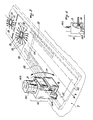
- the device comprises two separate components, indicated overall by 1 and 2, which have their axes mutually orthogonal and are positioned at different heights, the first component supporting a workholding table 3, and the second component 2 supporting an operating head 4.
- the component 1 which can be considered to be positioned along an X-axis, comprises an outer support housing 5 defining a tubular cavity of substantially square cross-section, and a mobile member 6 within the housing 5 and represented by a bar of triangular or square cross-section and preferably of polygonal perimeter. Said mobile member 6 is supported in the outer housing 5 on air cushions by three or four conventional pneumostatic shoes 7 delivering compressed air and disposed in a peripheral position about the member 6.
- a rectangular coil 9 immersed in a magnetic field generated by a pair of permanent magnets 10 supported in a C-shaped iron structure 11 connected by a plate 12 to the outer housing 5, said elements forming a known linear motor.
- the structure 11 has an intermediate core which penetrates into the coil 9.
- the coil and magnets can also be of cylindrical shape.
- a position sensor 13 is disposed between the outer housing 5 and the inner member 6 and consists of a conventional encoder formed from a reading part 13A rigid with the stationary outer housing 5, and an optical line 13B rigid with the inner mobile member 6, said encoder enabling the movement of the inner member 6 to be kept under control, this movement being effected by controlling the power supply to the coil 9.
- the inner member 6 can be moved in accordance with a determined program.
- the workholding table 3 comprising the elements for guiding the workpiece, elements for retaining the workpiece and elements required for the process to which the workpieces are to be subjected.
- Said elements comprise two or more grippers 14, a presser 15, a heating element 16 and two lateral guides 23.
- the grippers 14 are fixed directly onto the stationary outer housing 5 by bolts or other means 50 and comprise a pneumatic operating cylinder 14A and two jaws 17 and 18, of which the former is stationary and provided on a support 14B of the cylinder 14A, and the latter 18 is mobile (in the direction of the arrow F of Figure 3). It is rigid with the rod of the piston 14C provided in the operating cylinder 14A and moving along the gripper axis when urged pneumatically.
- the presser 15 lying in a horizontal plane, has an aperture 19 and is mobile relative to the member 6 which supports it, this movement being vertical in the direction of the arrow G of Figure 2.
- the movement in the direction of the arrow G is obtained by two pneumatic cylinders 20 mounted in the inner member 6 by means of a plate and screws 26 and 27. When said member 6 moves, the presser therefore moves in the same direction.
- the presser is supported by the rods of the pneumatic cylinders 20.
- the heating element 16 is positioned below the presser 15 and is also supported by the rod of a pneumatic cylinder 20A, which is also fixed to the plate 26.
- the workholding table 3 is fixed to the inner mobile member 6 by a plate 31 and bolts 32, it being inserted into the corridor 21 defined by the heating element 16 and presser 15 and comprises a structure 22 on which lateral guides 23 are defined for receiving the edges of a conventional metal strip 24 onto which the wires are to be bonded.
- the metal strip 24 comprises a succession of identical parts 30, each of which forms the conducting base of an electronic component (chip).
- This base comprises in its centre a island 25 on which a microcircuit has been previously attacked.
- conducting wires are bonded between the microcircuit and the base-surrounding parts 33 which are to form the pins of the electronic component.
- the said lateral guides comprise apertures 28 through which the jaws 17 and 18 of the grippers 14 can pass to grip the metal strip 24 and retain it during the movement of the presser 24, heating element 18 and structure 22 of the workholding table 3 when, having completed one bonding operation on a base element of the metal strip, the machine moves into position to bond the wires onto the next.
- its axis is orthogonal to that of the component 1 and can be defined as the Y-axis.
- Said second component 2 comprises an outer and inner structure similar to that of the component 1, namely a stationary outer support housing 5 ⁇ defining a tubular cavity, and a pneumostatically supported mobile inner member 6 ⁇ of polygonal perimeter driven axially in the same manner as the already described mobile inner member 6.
- the component 2 is positioned at a higher level than the component 1.
- a conventional operating head 4 comprising an ultrasonic transducer 28 carrying a capillary needle 29.
- the operating head can be constructed as described in USA patent 4,610,387.
- the operating head is however preferably simpler than that of the said patent in the sense of dispensing with those members indicated by 2, 3, 4 and 4 ⁇ in said patent and used to displace the pivotal pin 6 vertically.
- This pivotal pin is indicated herein by 34 and is supported at the ends of arms 35 which project from the mobile member 6 ⁇ .
- the operation of the device of the present invention is as follows: the metal strip 24 to which the connection wires for the electronic components are to be bonded is placed on the workholding table 3 and made to slide within its guides 23 in the direction of the arrow X of Figures 2 and 3. When positioned between the presser 15 and heating element 16, these move in opportune manner in the direction of the arrow G of Figure 2 to grip the metal strip 24 and clamp it.
- the operating head 4 is moved in the direction Y so that by rotating the capillary needle 29, the wire to be bonded is moved in the direction of the arrow Z of Figure 1 and brought into contact with the required point of the metal strip 24.
- the head 4 By controlled movement of the operating head 4 along the Y-axis, the head 4 also being provided with an encoder analogous to the encoder 13, by controlled movement of the strip along the X-axis and by controlled movement of the operating head 4 about the pivotal axis 34, the electronic component connection wires can be bonded onto the strip 24 in any orientation.
- the inner mobile member 6 is moved through one step in the direction in which the strips 24 are inserted (direction of arrow W in Figure 2).
- the presser 15, the heating element 16 and the structure 22 of the workholding table 3 consequently move rigid with the inner member 6, but not the strip 24 as this is immobilized by the grippers 14.
- the presser 15 and heating element 16 are closed together and the grippers 14 opened.
- the mobile member 6 is then moved through one step in the opposite direction to the preceding (ie in the direction of the arrow X of Figure 2), with the result that the new element 30 requiring bonding is moved into the bonded region.
- the exact position of the element 30 under the bonding capillary 29 is controlled by the position sensor 13 disposed between the outer housing 5 and the inner member 6, in a position opposite the heating element 16.
- This control combined with a motor control system for advancing the inner mobile member 6 enables said member to be moved in accordance with a determined program which takes account of the different dimensions of the workpieces.
- the aforesaid movements ie movement of the workpieces along an X-axis and movement of the operating head along a Y-axis, are repeated for every bonded unit, until the strip 24 is completed.
- the strip 24 is fed onto the workholding table 3 and expelled therefrom after completion of bonding by conventional systems such as air pistons or friction motors, not shown on the figures and not forming part of the present invention.
- the described system dispenses with the strip feed mechanism.
- Said system can however also be implemented using conventional rotary motors with lead screws and mechanical guides, ie without using linear motors and pneumatic cushioning, providing the components 1 and 2, and thus the X and Y axes, remain separated and the grippers 14 remain fixed on the outer housing of the component carrying the workpiece.
Landscapes
- Wire Bonding (AREA)
- Pressure Welding/Diffusion-Bonding (AREA)
Applications Claiming Priority (2)
| Application Number | Priority Date | Filing Date | Title |
|---|---|---|---|
| IT19899/87A IT1204967B (it) | 1987-03-30 | 1987-03-30 | Dispositivo ad assi ortogonali,con motori lineari per il posizionamento e lavorazione di pezzi,in particolare per la microsaldatura di fili su composnenti elettronici |
| IT1989987 | 1987-03-30 |
Publications (2)
| Publication Number | Publication Date |
|---|---|
| EP0287786A2 true EP0287786A2 (fr) | 1988-10-26 |
| EP0287786A3 EP0287786A3 (fr) | 1990-01-03 |
Family
ID=11162173
Family Applications (1)
| Application Number | Title | Priority Date | Filing Date |
|---|---|---|---|
| EP88103186A Withdrawn EP0287786A3 (fr) | 1987-03-30 | 1988-03-02 | Dispositif à axes orthogonaux avec moteurs linéaires pour positionner et usiner des pièces, en particulier pour souder des fils à des dispositifs électroniques |
Country Status (6)
| Country | Link |
|---|---|
| US (1) | US4838472A (fr) |
| EP (1) | EP0287786A3 (fr) |
| JP (1) | JPS63255931A (fr) |
| KR (1) | KR880012137A (fr) |
| CN (1) | CN88101753A (fr) |
| IT (1) | IT1204967B (fr) |
Cited By (2)
| Publication number | Priority date | Publication date | Assignee | Title |
|---|---|---|---|---|
| EP1785217A1 (fr) * | 2005-11-09 | 2007-05-16 | Fanuc Ltd | Dispositif d'usinage |
| WO2008030200A1 (fr) * | 2006-09-08 | 2008-03-13 | Oerlikon Assembly Equipment Pte. Ltd. | Préhenseur doté de trois mâchoires formant deux pinces |
Families Citing this family (9)
| Publication number | Priority date | Publication date | Assignee | Title |
|---|---|---|---|---|
| JP2534132B2 (ja) * | 1989-05-15 | 1996-09-11 | 株式会社新川 | ボンデイング方法 |
| JP2806722B2 (ja) * | 1992-12-01 | 1998-09-30 | 株式会社カイジョー | 基板搬送装置 |
| DE69405209T2 (de) * | 1994-03-31 | 1998-03-19 | Sgs Thomson Microelectronics | Verbindungsvorrichtung für elektronische Halbleiter-Einheiter |
| US5813590A (en) * | 1995-12-18 | 1998-09-29 | Micron Technology, Inc. | Extended travel wire bonding machine |
| JP4635420B2 (ja) * | 2003-08-29 | 2011-02-23 | 凸版印刷株式会社 | 間接流体式ダイヤフラムポンプ |
| AT501244B1 (de) * | 2004-12-29 | 2007-10-15 | Sticht Fertigungstech Stiwa | Verfahren zur herstellung einer baugruppe aus mehreren miteinander gefügten teilen |
| US20080073408A1 (en) * | 2006-09-22 | 2008-03-27 | Ka Shing Kenny Kwan | Movable electronic flame-off device for a bonding apparatus |
| US8231044B2 (en) * | 2010-10-01 | 2012-07-31 | Orthodyne Electronics Corporation | Solar substrate ribbon bonding system |
| CN105414851B (zh) * | 2015-12-29 | 2017-04-05 | 潍坊学院 | 改进型电子元件焊接用夹紧装置 |
Family Cites Families (8)
| Publication number | Priority date | Publication date | Assignee | Title |
|---|---|---|---|---|
| JPS5080763A (fr) * | 1973-11-14 | 1975-07-01 | ||
| US3960309A (en) * | 1974-07-31 | 1976-06-01 | International Business Machines Corporation | Fine wire twisted pair routing and connecting system |
| JPS5698900A (en) * | 1980-01-07 | 1981-08-08 | Hitachi Ltd | Device for automatically wiring printed circuit board |
| EP0063170A3 (fr) * | 1981-04-21 | 1983-08-31 | Rockwell International Corporation | Appareil pneumatique et méthode pour soulever des fils |
| US4561814A (en) * | 1981-07-09 | 1985-12-31 | Dahlgren Jr William V | Mechanical tool manipulating method and apparatus |
| JPS5890732A (ja) * | 1981-11-25 | 1983-05-30 | Toshiba Corp | 搬送装置 |
| US4583676A (en) * | 1982-05-03 | 1986-04-22 | Motorola, Inc. | Method of wire bonding a semiconductor die and apparatus therefor |
| IT8323884U1 (it) * | 1983-12-19 | 1985-06-19 | Scavino Mario | Dispositivo perfezionato per la saltatura di fili per componenti elettronici |
-
1987
- 1987-03-30 IT IT19899/87A patent/IT1204967B/it active
-
1988
- 1988-03-02 EP EP88103186A patent/EP0287786A3/fr not_active Withdrawn
- 1988-03-17 US US07/169,413 patent/US4838472A/en not_active Expired - Lifetime
- 1988-03-19 KR KR1019880002944A patent/KR880012137A/ko not_active Withdrawn
- 1988-03-23 JP JP63069179A patent/JPS63255931A/ja active Pending
- 1988-03-30 CN CN88101753A patent/CN88101753A/zh active Pending
Cited By (3)
| Publication number | Priority date | Publication date | Assignee | Title |
|---|---|---|---|---|
| EP1785217A1 (fr) * | 2005-11-09 | 2007-05-16 | Fanuc Ltd | Dispositif d'usinage |
| US7492066B2 (en) | 2005-11-09 | 2009-02-17 | Fanuc Ltd | Machining apparatus |
| WO2008030200A1 (fr) * | 2006-09-08 | 2008-03-13 | Oerlikon Assembly Equipment Pte. Ltd. | Préhenseur doté de trois mâchoires formant deux pinces |
Also Published As
| Publication number | Publication date |
|---|---|
| KR880012137A (ko) | 1988-11-03 |
| EP0287786A3 (fr) | 1990-01-03 |
| CN88101753A (zh) | 1988-10-19 |
| US4838472A (en) | 1989-06-13 |
| JPS63255931A (ja) | 1988-10-24 |
| IT8719899A0 (it) | 1987-03-30 |
| IT1204967B (it) | 1989-03-10 |
Similar Documents
| Publication | Publication Date | Title |
|---|---|---|
| US3960309A (en) | Fine wire twisted pair routing and connecting system | |
| US5735449A (en) | Method and apparatus for bonding semiconductor electronic devices | |
| US5813590A (en) | Extended travel wire bonding machine | |
| US4838472A (en) | Orthogonal axis device with linear motors for positioning and bonding wires onto electronic components | |
| CN105935835B (zh) | 板材加工系统以及板材加工方法 | |
| US4808892A (en) | Bi-directional drive motor system | |
| EP0478302B1 (fr) | Procédé et appareil de fabrication d'enroulements statoriques | |
| US20140109398A1 (en) | Automatic capillary replacement system | |
| US3664016A (en) | Apparatus and method for aligning a plurality of connector mounted pins by deformation and reformation thereof | |
| CN117754072A (zh) | 一种自动点焊设备 | |
| JPS6023582B2 (ja) | コイル插入装置 | |
| CN212010721U (zh) | 一种8头自动绕线机 | |
| US5410804A (en) | Method for manufacturing a single product from integrated circuits received on a lead frame | |
| JP4707870B2 (ja) | 抵抗溶接装置 | |
| US6397456B1 (en) | Method and a machine for automatic mounting of components and a pick-up head for such a machine | |
| CN215815595U (zh) | 一种新型八轴绕线焊锡机 | |
| JPH071746B2 (ja) | コイル製造装置 | |
| CA1234681A (fr) | Systeme d'assemblage programmable modulaire a prix modique | |
| CN113178323A (zh) | 电子元件绕线切割一体机 | |
| KR100195157B1 (ko) | 자동 콜렛 교환기 | |
| CN117105001B (zh) | 顺线设备 | |
| CN219040252U (zh) | 一种多轴自动绕线包胶带机 | |
| CN218631662U (zh) | 一种机械手及绕线机 | |
| CN219746574U (zh) | 一种电火花小孔机 | |
| CN220732563U (zh) | 用于马达定子定位组装结构 |
Legal Events
| Date | Code | Title | Description |
|---|---|---|---|
| PUAI | Public reference made under article 153(3) epc to a published international application that has entered the european phase |
Free format text: ORIGINAL CODE: 0009012 |
|
| AK | Designated contracting states |
Kind code of ref document: A2 Designated state(s): CH DE GB LI |
|
| PUAL | Search report despatched |
Free format text: ORIGINAL CODE: 0009013 |
|
| AK | Designated contracting states |
Kind code of ref document: A3 Designated state(s): CH DE GB LI |
|
| 17P | Request for examination filed |
Effective date: 19900528 |
|
| 17Q | First examination report despatched |
Effective date: 19910724 |
|
| STAA | Information on the status of an ep patent application or granted ep patent |
Free format text: STATUS: THE APPLICATION HAS BEEN WITHDRAWN |
|
| 18W | Application withdrawn |
Withdrawal date: 19920306 |