EP0288044B2 - Appareil d'enregistrement à jet d'encre avec fonction de contrÔle de densité - Google Patents
Appareil d'enregistrement à jet d'encre avec fonction de contrÔle de densité Download PDFInfo
- Publication number
- EP0288044B2 EP0288044B2 EP88106339A EP88106339A EP0288044B2 EP 0288044 B2 EP0288044 B2 EP 0288044B2 EP 88106339 A EP88106339 A EP 88106339A EP 88106339 A EP88106339 A EP 88106339A EP 0288044 B2 EP0288044 B2 EP 0288044B2
- Authority
- EP
- European Patent Office
- Prior art keywords
- ink
- density
- ink jet
- pulse width
- nozzles
- Prior art date
- Legal status (The legal status is an assumption and is not a legal conclusion. Google has not performed a legal analysis and makes no representation as to the accuracy of the status listed.)
- Expired - Lifetime
Links
Images


Classifications
-
- B—PERFORMING OPERATIONS; TRANSPORTING
- B41—PRINTING; LINING MACHINES; TYPEWRITERS; STAMPS
- B41J—TYPEWRITERS; SELECTIVE PRINTING MECHANISMS, i.e. MECHANISMS PRINTING OTHERWISE THAN FROM A FORME; CORRECTION OF TYPOGRAPHICAL ERRORS
- B41J2/00—Typewriters or selective printing mechanisms characterised by the printing or marking process for which they are designed
- B41J2/005—Typewriters or selective printing mechanisms characterised by the printing or marking process for which they are designed characterised by bringing liquid or particles selectively into contact with a printing material
- B41J2/01—Ink jet
- B41J2/21—Ink jet for multi-colour printing
- B41J2/2121—Ink jet for multi-colour printing characterised by dot size, e.g. combinations of printed dots of different diameter
- B41J2/2128—Ink jet for multi-colour printing characterised by dot size, e.g. combinations of printed dots of different diameter by means of energy modulation
Definitions
- the present invention relates generally to an ink jet recording apparatus, and more particularly to such an ink jet recording apparatus with a multi-nozzle type ink jet printing head which allows gradation control of the recording density when ink is ejected from each of a plurality of ink nozzles of the multi-nozzle type ink jet printing head toward a writing surface placed in opposed relation to the printing head.
- Various types of ink jet printers are devised heretofore and one known arrangement is to use a multi-nozzle ink jet printing head of the type wherein printing ink is ejected therefrom toward a writing surface by the aid of an electric field established between two types of electrodes and air-stream supplied from a pressurized air source.
- a multi-nozzle ink jet printing head is illustrated in U.S. Patent No. 4,555,717, for example.
- An important problem in such multi-nozzle ink jet printing heads relates to the lack of uniformity in recording thickness or density on a writing surface. This is due to the difference in characteristic between the nozzles of the multi-nozzle ink jet printing head.
- Document US-4 521 786 discloses a programmable controller for ink jet printheads which improves print quality by controlling pulse width and pulse amplitude of a drive pulse for each ink jet ejector.
- This programmable controller is used in a system wherein a control processor contains look-up tables necessary to provide the desired amplitude and width data of the drive pulse necessary for a desired drop ejection velocity and droplet size.
- this object is achieved by an ink jet recording apparatus according to claim 4.
- a prior multi-nozzle ink jet printing head as shown in Fig. 1, comprises an insulating air-ink nozzle plate 81 having a plurality of air-ink nozzles 82 to 85 successively arranged in a row at a predetermined interval.
- a common electrode 86 is attached at the circumferential portions of the plurality of air-ink nozzles 82 to 85 to a surface of the insulating air-ink nozzle plate 81.
- an ink nozzle plate 87 having a plurality of ink nozzles 88 to 91 successively arranged in a row and aligned with the air-ink nozzles 82 to 85 with one-to-one correspondance therebetween.
- the respective ink nozzles 88 to 91 are coupled to an ink chamber 93 with ink which is in turn coupled through an ink supply passage 92 to an ink source, not shown.
- the respective air-ink nozzles 82 to 85 are coupled through an air chamber 95 and an air supply passage 94 to an air source, not shown so that air supplied from the air supply passage 94 makes an air stream 96 because of the ink nozzle plate 87 and is then discharged curvedly from the air-ink nozzles 82 to 85.
- Control electrodes 100 whose number corresponding to the number of the ink nozzles 88 to 91 are independently provided at the circumferential portions of the ink nozzles 88 to 91 and on the rear surface of the ink nozzle plate 87 facing the ink chamber 93.
- An electric field is established between the common electrode 86 and the control electrodes 100 to form meniscuses in the ink nozzles 88 to 91 and, in response to selective application of ink-ejection control signals 96 to 99 to the control electrodes 100, the meniscuses in the selected ink nozzles are extended toward the air-ink nozzles 82 to 85 and carried by the air-stream 96 so as to be ejected as inkdroplets from the corresponding air-ink nozzles.
- This type ink jet printing head is arranged to cause ink to discharge due to an electrostatic force produced in response to the application of the ink-ejection control signals 96 to 99 which are pulse signals, respectively.
- the ink-discharging amount, i.e., recording density is substantially proportional to the pulse width, or length, of each of the ink-ejection control signals applied to the control electrodes 88 to 91 and thus controllable under control of the pulse width thereof.
- Fig. 2 is a block diagram showing a device for generating the ink-ejection control pulse signals which are in turn applied to n ink nozzles of a multi-nozzle type ink jet printing head such as illustrated in Fig. 1.
- the control pulse generating device 110 comprises a pulse width control circuit 152 which produces pulse signals 111 to 114 with pulse widths corresponding to N-bit input signals 101 to 104 respectively having information relating to the recording densities in correspondance with the respective ink nozzles 141 to 144 of the multi-nozzle type ink jet printing head 140.
- the produced pulse signals 111 to 114 are respectively supplied through amplifiers 121 to 124 to the control electrodes of the ink nozzles 141 to 144.
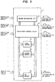
- a memory 153 which stores density-pulse width characteristic curves as illustrated in Fig. 3.
- the memory in response to inputs of the N-bit density information signals 101 to 104, the memory is controlled to convert them into l-bit pulse width information signals respectively corresponding to the inputted density information signals 101 to 104 which are in turn supplied to the pulse width control circuit 152 which produces the corresponding one-bit pulse width signals 111 to 114 and supplies them through the amplifiers 121 to 124 to the control electrodes of the ink nozzles 141 to 144, resulting in ink discharges with amounts corresponding to the density information.
- this arrangement causes recording density irregularity irrespective of application of control signals with the same pulse width, because of the difference in the density-pulse width characteristic between the ink nozzles as shown in Fig. 4.
- a control pulse generating unit according to an embodiment of the present invention designated at numeral 1, which may be coupled to a multi-nozzle type ink jet printing head such as shown in Fig. 1 and which comprises a pulse width control circuit 2 for, at every ink nozzles, producing a pulse signal with the width corresponding to a N-bit density information signal inputted from the external circuit.
- a density-pulse width characteristic curve is determined at every ink nozzle so that the number n of the ink nozzles equals to the number m of the density-pulse width characteristic curves, it is sufficient in practice that m density-pulse width characteristic curves are prepared and one of the m density-pulse width characteristic curves is selected to be closer to the density-pulse characteristic curve of each of the n ink nozzles (n > m).
- Illustrated at numeral 3 is a memory designating circuit for specifying memories in correspondance with the ink nozzles, respectively, which is presetable from the external.
- the memory designating circuit 3 are preset and stored addresses of the memories 11 to 13 which respectively prestore the density-pulse width characteristic curves corresponding to the respective ink nozzles of a multi-nozzle type ink jet printing head used in this ink jet recording apparatus.
- the memory designating circuit In response to inputting of each of N-bit density information signals for the respective ink nozzles to the control pulse generating unit 1, the memory designating circuit generates a k-bit memory address signal on the basis of each of the density information signals at every nozzle and the pulse width control circuit 2 obtains a l-bit pulse width information signal on the basis of each of the density information signals and the density-pulse width characteristic curve stored in the corresponding memory (k and l are positive integers).
- the pulse width control circuit 2 further produces a one-bit pulse signal with width corresponding to each of the pulse width information signals which is in turn supplied to the control electrode of each of the ink nozzles after amplified by amplifying means.
Landscapes
- Particle Formation And Scattering Control In Inkjet Printers (AREA)
Claims (5)
- Imprimante à jet d'encre, comprenant :- un moyen formant tête d'impression par jet d'encre qui comprend une pluralité de buses à encre (141-144) dont chacune envoie de l'encre vers une surface d'écriture, caractérisée par :- des moyens (11-13) pour mémoriser une pluralité de courbes caractéristiques prédéterminées largeur d'impulsion/densité qui représentent chacune une relation entre une densité souhaitée d'enregistrement et la largeur d'impulsion par conséquent requise pour un signal d'éjection d'encre qu'il faut appliquer à l'une respective des buses à encre de ladite pluralité (141-144), et- un moyen de commande (1) servant à choisir l'une des courbes parmi ladite pluralité de courbes caractéristiques prédéterminées largeur d'impulsion/densité en correspondance avec ladite buse à encre de la pluralité (141-144) et à produire ledit signal d'éjection d'encre en accord avec ladite courbe caractéristique largeur d'impulsion/densité choisie, de sorte que pour chaque buse à encre de ladite pluralité (141-144), l'une desdites courbes caractéristiques prédéterminées largeur d'impulsion/densité de la pluralité est choisie.
- Imprimante à jet d'encre selon la revendication 1, caractérisée en ce que ledit moyen formant tête d'impression par jet d'encre est une tête à signal et ladite pluralité de buses à encre (141-144) est disposée intégralement dans une rangée.
- Imprimante à jet d'encre selon la revendication 1, caractérisée en ce que ledit moyen formant tête d'impression par jet d'encre comprend une pluralité de têtes d'impression (140) par jet d'encre contenant chacune l'une des buses à encre de ladite pluralité (141-144).
- Appareil d'enregistrement par jet d'encre, comprenant :- une tête d'impression par jet d'encre, du type à buses multiples, qui comprend une pluralité de buses à encre (141-144) dont chacune envoie de l'encre vers une surface d'écriture, caractérisé par :- des moyens formant électrodes (86, 100) servant à établir un champ électrique dû à des signaux d'éjection d'encre appliqués auxdits moyens formant électrodes (86, 100), de façon à éjecter de l'encre depuis chaque buse de ladite pluralité de buses à encre (141-144) au moyen dudit champ électrique,- un moyen (2) de détermination de la densité, servant à produire des signaux d'information de densité indiquant chacun une densité d'enregistrement au niveau de l'une respective desdites buses à encre de la pluralité (141-144) de ladite tête d'impression par jet d'encre du type à buses multiples, et- un moyen de commande (1) répondant audit moyen (2) de détermination de densité et comportant des moyens formant mémoire (11-13) qui stockent une pluralité de courbes caractéristiques largeur d'impulsion/densité dont chacune est prédéterminée pour correspondre à une ou plusieurs desdites buses à encre (141-144) et dont chacune représente une relation entre ladite densité d'enregistrement et la largeur d'impulsion par conséquent requise pour l'un respectifs desdits signaux d'éjection d'encre indiquant une quantité d'encre éjectée par ladite ou lesdites buse (s) à encre (141-144), servant à choisir l'une respective desdites courbes caractéristiques largeur d'impulsion/densité pour chaque buse à encre (141-144) et servant à produire ledit signal d'éjection d'encre indiquant ladite quantité d'encre à éjecter, déterminée sur la base dudit signal d'information de densité provenant dudit moyen (2) de détermination de la densité en accord avec ladite courbe caractéristique largeur d'impulsion/densité choisie, chacun desdits signaux d'éjection d'encre étant appliqué auxdits moyens formant électrodes (86, 100).
- Appareil d'enregistrement par jet d'encre selon la revendication 4, caractérisé en ce que lesdits moyens formant électrodes (86, 100) de ladite tête d'impression par jet d'encre du type à buses multiples comprennent une électrode commune (86) et une pluralité d'électrodes de commande (100) dont chacune est placée en correspondance avec chacune des buses à encre de ladite pluralité (88-91) et est positionnée en vis-à-vis de ladite électrode commune, ledit signal d'impulsion qui a une largeur correspondant audit signal d'information de densité étant appliqué à ladite électrode de commande correspondante (100).
Applications Claiming Priority (2)
| Application Number | Priority Date | Filing Date | Title |
|---|---|---|---|
| JP102254/87 | 1987-04-24 | ||
| JP62102254A JPH0729421B2 (ja) | 1987-04-24 | 1987-04-24 | インクジエツトプリンタ |
Publications (4)
| Publication Number | Publication Date |
|---|---|
| EP0288044A2 EP0288044A2 (fr) | 1988-10-26 |
| EP0288044A3 EP0288044A3 (en) | 1990-08-29 |
| EP0288044B1 EP0288044B1 (fr) | 1993-11-24 |
| EP0288044B2 true EP0288044B2 (fr) | 1997-07-09 |
Family
ID=14322458
Family Applications (1)
| Application Number | Title | Priority Date | Filing Date |
|---|---|---|---|
| EP88106339A Expired - Lifetime EP0288044B2 (fr) | 1987-04-24 | 1988-04-20 | Appareil d'enregistrement à jet d'encre avec fonction de contrÔle de densité |
Country Status (4)
| Country | Link |
|---|---|
| US (1) | US4908635A (fr) |
| EP (1) | EP0288044B2 (fr) |
| JP (1) | JPH0729421B2 (fr) |
| DE (1) | DE3885787T3 (fr) |
Families Citing this family (46)
| Publication number | Priority date | Publication date | Assignee | Title |
|---|---|---|---|---|
| US5225849A (en) * | 1988-06-17 | 1993-07-06 | Canon Kabushiki Kaisha | Image recording apparatus and method for performing recording by making ink adhere to a recording medium and incorporating image data correction |
| JP2746633B2 (ja) * | 1989-02-08 | 1998-05-06 | キヤノン株式会社 | 液体噴射記録装置 |
| JP3144676B2 (ja) * | 1989-02-14 | 2001-03-12 | キヤノン株式会社 | 画像形成用制御装置及び画像形成装置 |
| US5610639A (en) * | 1989-02-14 | 1997-03-11 | Canon Kabushiki Kaisha | Image forming apparatus with a correction recording condition feature and related method |
| JP2804513B2 (ja) * | 1989-06-02 | 1998-09-30 | キヤノン株式会社 | インクジェット記録装置 |
| EP0421806B1 (fr) * | 1989-10-05 | 1999-03-17 | Canon Kabushiki Kaisha | Appareil de formation de l'image |
| JPH03140252A (ja) * | 1989-10-27 | 1991-06-14 | Canon Inc | インクジェットヘッドおよびインクジェット装置 |
| US5512922A (en) * | 1989-10-10 | 1996-04-30 | Xaar Limited | Method of multi-tone printing |
| DE69015953T2 (de) * | 1989-10-10 | 1995-05-11 | Xaar Ltd | Druckverfahren mit mehreren Tonwerten. |
| JP3083826B2 (ja) * | 1989-10-24 | 2000-09-04 | キヤノン株式会社 | 画像記録装置 |
| JP3040407B2 (ja) * | 1989-11-22 | 2000-05-15 | キヤノン株式会社 | 画像記録装置 |
| US5285220A (en) * | 1989-11-22 | 1994-02-08 | Canon Kabushiki Kaisha | Image recording apparatus with tone correction for individual recording heads |
| EP0430075B1 (fr) * | 1989-11-22 | 2000-02-09 | Canon Kabushiki Kaisha | Dispositif d'enregistrement d'images avec tête d'enregistrement |
| JP3059451B2 (ja) * | 1989-11-22 | 2000-07-04 | キヤノン株式会社 | 画像記録装置 |
| JPH0686125B2 (ja) * | 1989-11-27 | 1994-11-02 | 松下電器産業株式会社 | 画像記録方法 |
| JPH03213345A (ja) * | 1990-01-19 | 1991-09-18 | Canon Inc | 液体噴射記録方法 |
| JP2857445B2 (ja) * | 1990-02-02 | 1999-02-17 | キヤノン株式会社 | 記録ヘッドおよび記録装置 |
| EP0440490B1 (fr) * | 1990-02-02 | 1995-12-06 | Canon Kabushiki Kaisha | Procédé et appareil d'enregistrement |
| JPH045054A (ja) * | 1990-04-24 | 1992-01-09 | Canon Inc | インクジェットプリンタ |
| US5353052A (en) * | 1990-05-11 | 1994-10-04 | Canon Kabushiki Kaisha | Apparatus for producing unevenness correction data |
| JPH0418357A (ja) * | 1990-05-11 | 1992-01-22 | Canon Inc | 画像記録装置および記録画像補正方法 |
| US6000776A (en) * | 1990-05-11 | 1999-12-14 | Canon Kabushiki Kaisha | Apparatus and method for regulating image density |
| US5036337A (en) * | 1990-06-22 | 1991-07-30 | Xerox Corporation | Thermal ink jet printhead with droplet volume control |
| US5130720A (en) * | 1990-11-09 | 1992-07-14 | Dataproducts Corporation | System for driving ink jet transducers and method of operation |
| US6116710A (en) * | 1991-01-18 | 2000-09-12 | Canon Kabushiki Kaisha | Ink jet recording method and apparatus using thermal energy |
| ATE237474T1 (de) * | 1991-01-18 | 2003-05-15 | Canon Kk | Tintenstrahlaufzeichnungsverfahren und - vorrichtung mit thermischer energie |
| JP2859759B2 (ja) * | 1991-07-26 | 1999-02-24 | キヤノン株式会社 | 記録装置および濃度むら補正方法 |
| US6036300A (en) * | 1992-02-26 | 2000-03-14 | Canon Kabushiki Kaisha | Method for recording image and apparatus therefor and recorded matter by such an apparatus |
| JPH068474A (ja) * | 1992-06-26 | 1994-01-18 | Canon Inc | インクジェット記録装置 |
| DE69331682T2 (de) * | 1993-01-08 | 2002-08-22 | Canon K.K., Tokio/Tokyo | Aufzeichnungsverfahren zur Gradationsaufzeichnung mit hell- und dunkelfarbigen Tinten und Gerät dafür |
| US6116714A (en) | 1994-03-04 | 2000-09-12 | Canon Kabushiki Kaisha | Printing head, printing method and apparatus using same, and apparatus and method for correcting said printing head |
| US5663750A (en) * | 1994-04-05 | 1997-09-02 | Brother Kogyo Kabushiki Kaisha | Ink ejection device with ink saving mode used when remaining ink amount is small |
| US5969730A (en) * | 1994-11-07 | 1999-10-19 | Canon Aptex Inc. | Printer |
| US6270178B1 (en) | 1995-05-30 | 2001-08-07 | Canon Kabushiki Kaisha | Method and apparatus for measuring the amount of discharged ink, printing apparatus, and method of measuring the amount of ink discharged in the printing apparatus |
| JPH09216361A (ja) * | 1995-12-05 | 1997-08-19 | Tec Corp | インクジェットプリンタのヘッド駆動装置 |
| KR100242853B1 (ko) * | 1996-12-19 | 2000-03-02 | 미다라이 후지오 | 잉크 배출량의 측정 방법 및 장치, 인쇄 장치, 및인쇄 장치에서의 잉크 배출량 측정 방법 |
| US6109732A (en) * | 1997-01-14 | 2000-08-29 | Eastman Kodak Company | Imaging apparatus and method adapted to control ink droplet volume and void formation |
| US6312078B1 (en) | 1997-03-26 | 2001-11-06 | Eastman Kodak Company | Imaging apparatus and method of providing images of uniform print density |
| EP0867284A3 (fr) * | 1997-03-26 | 1999-08-25 | Eastman Kodak Company | Appareil d'imagerie et methode adaptée pour contrÔler le volume des gouttes d'encre et la formation de bulles |
| US6270188B1 (en) * | 1998-01-29 | 2001-08-07 | Fuji Photo Film Co., Ltd. | Ink jet printer and control method thereof |
| US6116717A (en) * | 1998-09-15 | 2000-09-12 | Lexmark International, Inc. | Method and apparatus for customized control of a print cartridge |
| US6299272B1 (en) * | 1999-10-28 | 2001-10-09 | Xerox Corporation | Pulse width modulation for correcting non-uniformity of acoustic inkjet printhead |
| US20020149785A1 (en) * | 2001-03-30 | 2002-10-17 | Chia-Lin Chu | Automatic printer color correction based on characterization data of a color ink cartridge |
| JP2005193221A (ja) * | 2003-02-25 | 2005-07-21 | Seiko Epson Corp | 駆動波形決定装置、電気光学装置および電子機器 |
| CN101385010A (zh) * | 2003-12-18 | 2009-03-11 | 霍尼韦尔国际公司 | 用于印刷介质的闭环色彩控制的系统和方法 |
| US8329480B2 (en) * | 2010-09-28 | 2012-12-11 | Macronix International Co., Ltd. | Test pattern for detecting piping in a memory array |
Family Cites Families (11)
| Publication number | Priority date | Publication date | Assignee | Title |
|---|---|---|---|---|
| JPS58220758A (ja) | 1982-06-16 | 1983-12-22 | Matsushita Electric Ind Co Ltd | インクジエツト記録装置 |
| JPS5942965A (ja) * | 1982-09-04 | 1984-03-09 | Hitachi Ltd | インクジエツトプリンタ |
| US4521786A (en) * | 1982-09-20 | 1985-06-04 | Xerox Corporation | Programmable driver/controller for ink jet printheads |
| JPS59137040U (ja) * | 1983-03-04 | 1984-09-12 | 日立工機株式会社 | インクジエツトプリンタのノズル駆動装置 |
| JPH0679853B2 (ja) * | 1983-12-09 | 1994-10-12 | キヤノン株式会社 | 液体噴射装置 |
| EP0150119A3 (fr) * | 1984-01-20 | 1986-05-28 | Nec Corporation | Système d'enregistrement à jet d'encre capable d'enregistrer les demi-tons |
| JPS6148273A (ja) * | 1984-08-14 | 1986-03-08 | Hitachi Ltd | 記録信号補正方法 |
| US4547784A (en) * | 1984-12-24 | 1985-10-15 | Polaroid Corporation | Thermal recording system and method |
| DE3612469C2 (de) * | 1985-04-15 | 1999-02-18 | Canon Kk | Tintenstrahl-Aufzeichnungsgerät |
| US4710784A (en) * | 1985-07-11 | 1987-12-01 | Tokyo Electric Co., Ltd. | Ink jet printing device |
| JPS62144639U (fr) * | 1986-03-10 | 1987-09-11 |
-
1987
- 1987-04-24 JP JP62102254A patent/JPH0729421B2/ja not_active Expired - Fee Related
-
1988
- 1988-04-20 EP EP88106339A patent/EP0288044B2/fr not_active Expired - Lifetime
- 1988-04-20 DE DE3885787T patent/DE3885787T3/de not_active Expired - Fee Related
- 1988-04-22 US US07/185,020 patent/US4908635A/en not_active Expired - Lifetime
Also Published As
| Publication number | Publication date |
|---|---|
| JPS63267559A (ja) | 1988-11-04 |
| JPH0729421B2 (ja) | 1995-04-05 |
| EP0288044A2 (fr) | 1988-10-26 |
| DE3885787T2 (de) | 1994-03-24 |
| EP0288044A3 (en) | 1990-08-29 |
| US4908635A (en) | 1990-03-13 |
| DE3885787D1 (de) | 1994-01-05 |
| EP0288044B1 (fr) | 1993-11-24 |
| DE3885787T3 (de) | 1997-10-09 |
Similar Documents
| Publication | Publication Date | Title |
|---|---|---|
| EP0288044B2 (fr) | Appareil d'enregistrement à jet d'encre avec fonction de contrÔle de densité | |
| US5581286A (en) | Multi-channel array actuation system for an ink jet printhead | |
| JP4777465B2 (ja) | インクジェットプリントヘッドによる印刷方法、インクジェットプリントヘッド、インクジェットプリントヘッドの作動方法、インクジェットプリントヘッドの為の駆動回路及び液滴の平均の速度制御方法 | |
| US5600349A (en) | Method of reducing drive energy in a high speed thermal ink jet printer | |
| JP3152243B2 (ja) | 高周波数ドロップオンデマンド型インクジェットシステム | |
| US4126867A (en) | Ink jet printer driving circuit | |
| US4350989A (en) | Ink-jet printing apparatus | |
| US6932453B2 (en) | Inkjet printhead assembly having very high drop rate generation | |
| EP1174265A3 (fr) | Tête d'enregistrement à jet d'encre | |
| EP0941852A3 (fr) | Dispositif et procédé d'enregistrement à jet d'encre | |
| JP2746633B2 (ja) | 液体噴射記録装置 | |
| EP1332876A3 (fr) | Imprimante à jet d'encre et méthode d'impression | |
| HK16193A (en) | Operating an ink jet apparatus | |
| JPS5843026B2 (ja) | 非衝撃式印刷装置 | |
| JP3412569B2 (ja) | インクジェット記録ヘッドの駆動方法及び駆動装置 | |
| US6419336B1 (en) | Ink ejector | |
| KR960031147A (ko) | 프린트헤드 보정 장치, 프린트헤드 및 이를 사용한 프린팅 장치, 및 프린트헤드 보정방법 | |
| JPS6144071B2 (fr) | ||
| US6679586B2 (en) | Inkjet recording device capable of performing ink refresh operation without stopping printing operation | |
| JP3324429B2 (ja) | インクジェット記録装置 | |
| JP3959809B2 (ja) | インクジェットプリンタ、ならびにインクジェットプリンタ用記録ヘッドの駆動装置および方法 | |
| US6328402B1 (en) | Ink jet recording apparatus that can reproduce half tone image without degrading picture quality | |
| US6130691A (en) | Inkjet recording apparatus having specific driving circuitry for driving electrophoresis electrodes | |
| JP2785701B2 (ja) | インクジェット式プリンタヘッド及びその駆動方法 | |
| JP3228129B2 (ja) | インクジェット記録装置 |
Legal Events
| Date | Code | Title | Description |
|---|---|---|---|
| PUAI | Public reference made under article 153(3) epc to a published international application that has entered the european phase |
Free format text: ORIGINAL CODE: 0009012 |
|
| 17P | Request for examination filed |
Effective date: 19880420 |
|
| AK | Designated contracting states |
Kind code of ref document: A2 Designated state(s): DE FR GB |
|
| PUAL | Search report despatched |
Free format text: ORIGINAL CODE: 0009013 |
|
| AK | Designated contracting states |
Kind code of ref document: A3 Designated state(s): DE FR GB |
|
| 17Q | First examination report despatched |
Effective date: 19920724 |
|
| GRAA | (expected) grant |
Free format text: ORIGINAL CODE: 0009210 |
|
| AK | Designated contracting states |
Kind code of ref document: B1 Designated state(s): DE FR GB |
|
| ET | Fr: translation filed | ||
| REF | Corresponds to: |
Ref document number: 3885787 Country of ref document: DE Date of ref document: 19940105 |
|
| PLBI | Opposition filed |
Free format text: ORIGINAL CODE: 0009260 |
|
| PLBI | Opposition filed |
Free format text: ORIGINAL CODE: 0009260 |
|
| 26 | Opposition filed |
Opponent name: CANON KABUSHIKI KAISHA Effective date: 19940823 |
|
| 26 | Opposition filed |
Opponent name: GERGANOFF, KONSTANTIN Effective date: 19940824 Opponent name: CANON KABUSHIKI KAISHA Effective date: 19940823 |
|
| REG | Reference to a national code |
Ref country code: GB Ref legal event code: 746 Effective date: 19951123 |
|
| REG | Reference to a national code |
Ref country code: FR Ref legal event code: D6 |
|
| PLAW | Interlocutory decision in opposition |
Free format text: ORIGINAL CODE: EPIDOS IDOP |
|
| PLAW | Interlocutory decision in opposition |
Free format text: ORIGINAL CODE: EPIDOS IDOP |
|
| PUAH | Patent maintained in amended form |
Free format text: ORIGINAL CODE: 0009272 |
|
| STAA | Information on the status of an ep patent application or granted ep patent |
Free format text: STATUS: PATENT MAINTAINED AS AMENDED |
|
| 27A | Patent maintained in amended form |
Effective date: 19970709 |
|
| AK | Designated contracting states |
Kind code of ref document: B2 Designated state(s): DE FR GB |
|
| ET3 | Fr: translation filed ** decision concerning opposition | ||
| REG | Reference to a national code |
Ref country code: GB Ref legal event code: IF02 |
|
| PGFP | Annual fee paid to national office [announced via postgrant information from national office to epo] |
Ref country code: FR Payment date: 20030408 Year of fee payment: 16 |
|
| PGFP | Annual fee paid to national office [announced via postgrant information from national office to epo] |
Ref country code: GB Payment date: 20030416 Year of fee payment: 16 |
|
| PGFP | Annual fee paid to national office [announced via postgrant information from national office to epo] |
Ref country code: DE Payment date: 20030502 Year of fee payment: 16 |
|
| PG25 | Lapsed in a contracting state [announced via postgrant information from national office to epo] |
Ref country code: GB Free format text: LAPSE BECAUSE OF NON-PAYMENT OF DUE FEES Effective date: 20040420 |
|
| PG25 | Lapsed in a contracting state [announced via postgrant information from national office to epo] |
Ref country code: DE Free format text: LAPSE BECAUSE OF NON-PAYMENT OF DUE FEES Effective date: 20041103 |
|
| GBPC | Gb: european patent ceased through non-payment of renewal fee |
Effective date: 20040420 |
|
| PG25 | Lapsed in a contracting state [announced via postgrant information from national office to epo] |
Ref country code: FR Free format text: LAPSE BECAUSE OF NON-PAYMENT OF DUE FEES Effective date: 20041231 |
|
| REG | Reference to a national code |
Ref country code: FR Ref legal event code: ST |