EP0288078A2 - Lauthörfernsprechgerät mit digital komprimiertem Tonanteil zwecks Regelung der Sprachkanalverstärkung - Google Patents
Lauthörfernsprechgerät mit digital komprimiertem Tonanteil zwecks Regelung der Sprachkanalverstärkung Download PDFInfo
- Publication number
- EP0288078A2 EP0288078A2 EP88106502A EP88106502A EP0288078A2 EP 0288078 A2 EP0288078 A2 EP 0288078A2 EP 88106502 A EP88106502 A EP 88106502A EP 88106502 A EP88106502 A EP 88106502A EP 0288078 A2 EP0288078 A2 EP 0288078A2
- Authority
- EP
- European Patent Office
- Prior art keywords
- coupled
- signals
- speakerphone
- signal
- control
- Prior art date
- Legal status (The legal status is an assumption and is not a legal conclusion. Google has not performed a legal analysis and makes no representation as to the accuracy of the status listed.)
- Granted
Links
Images




Classifications
-
- H—ELECTRICITY
- H04—ELECTRIC COMMUNICATION TECHNIQUE
- H04M—TELEPHONIC COMMUNICATION
- H04M9/00—Arrangements for interconnection not involving centralised switching
- H04M9/08—Two-way loud-speaking telephone systems with means for conditioning the signal, e.g. for suppressing echoes for one or both directions of traffic
- H04M9/085—Two-way loud-speaking telephone systems with means for conditioning the signal, e.g. for suppressing echoes for one or both directions of traffic using digital techniques
Definitions
- the present invention relates generally to speakerphones, and more particularly to an improved speakerphone using digitally compressed audio to control voice path gain that can advantageously be utilized in mobile radiotelephones.
- a user communicates by means of a handset that includes a speaker at one end which is placed close the user's ear and a microphone at the other end which is held close to the user's mouth.
- speakerphones have been developed for use in landline telephone systems.
- Conventional speakerphones such as that described in U.S. patent no. 3,751,602, are coupled to the telephone line and when enabled allow the user to freely move about while still communicating with another party. Such speakerphones typically compare the volume or the two parties and select the party speaking the loudest.
- conventional speakerphones always revert to the listen mode a short time interval after the hands-free party stops talking.
- conventional speakerphones suffer from a number of problems including inability to accommodate high ambient noise environments and breakup due to feedback from the speaker to the microphone when the speaker amplification has been turned up.
- these conventional speakerphones work reasonably well when utilized with landline telephones in relatively quiet surroundings, they do not operate correctly when used in noisy environments and especially when used with a radio due to the high degree of ambient noise encountered in vehicles. For example, a high level of ambient noise may cause such speakerphones to always select the hands-free party.
- a speakerphone for a radiotelephone for communicating voice signals by way of a radio channel
- said radiotelephone including radio means for transmitting a first signal including voice signals on and receiving a second signal including voice signals from the radio channel
- said speakerphone including microphone means for producing the first signal and speaker means for emitting the second signal and said speakerphone further CHARACTERIZED BY: compressor amplifying means having an input coupled to said microphone means and an output coupled to said radio means and being responsive to first control signals for selecting one of a plurality of gain settings and amplifying and compressing the first signal; expander amplifying means having an input coupled to said radio means and an output coupled to said speaker means and being responsive to second control signals for selecting one of a plurality of gain settings and amplifying and expanding the second signal; and control means coupled to the output of said compressor amplifying means and the input of said expander amplifying means for detecting voice signals in the first and second signals and, in response to detection of voice signals in one of the first and second signals, producing the
- FIG. 1 there is illustrated a communications system including landline telephones 138 and mobile radiotelephones 120 (hereinafter referred to as "mobiles") that may advantageously utilize the improved speakerphone of the present invention.
- Mobile 120 includes mobile radio 112, microphone 102 and speaker 104 for hands-free communications, mobile telephone 108 including a conventional hand-held handset, and speakerphone control circuitry 106 for interfacing microphone 102, speaker 104 and mobile telephone 108 to mobile radio 112.
- the improved speakerphone of the present invention includes microphone 102, speaker 104 and speakerphone control circuitry 106.
- Mobile telephone 108 may be a handset or a handset and cradle that includes conventional circuitry for controlling operation of mobile radio 112.
- Mobile radio 112 may be any conventional radiotelephone, such as an IMTS (Improved Mobile Telephone Service) radiotelephone or cellular radiotelephone. Further details of the signalling process and the nature of the circuitry for mobile telephone 108 and mobile radio 112 are provided in Motorola Service Manuals 68P81039E25, 68P81029E65 and 68P81037E85, all of which are published by and available from Motorola Service Publications, Schaumburg, Illinois.
- IMTS International Mobile Telephone Service
- a party in a vehicle communicates by way of mobile 120 with a base station 122 which is interconnected by a control terminal 124 to a landline telephone central office 126.
- Control terminal 124 includes control circuitry that provides a communication path from the base station 122 to hybrid circuitry (not shown, but similar to block 142) which is interconnected to a telephone line or trunk of telephone central office 126.
- hybrid circuitry not shown, but similar to block 142
- a number dialled by the mobile party by means of mobile 120 is received by the control terminal 124 and forwarded to the telephone central office 126 on the telephone line or trunk.
- the telephone central office 126 receives the dialled telephone number and routes the mobile party by way of landline 144 to the desired land party telephone, i.e., to hybrid circuitry 142 and landline telephone 138.
- Hybrid y 142 includes conventional circuitry that interfaces landline telephone 138 to duplex landline 144.
- Hybrid circuitry 142 is typically part of landline telephone 138.
- a similar process is employed when a land party dials the number of a mobile party by means of conventional telephone 138.
- control terminal 124 Further details of the signalling process and the nature of the circuitry for control terminal 124 is provided in Motorola Service Manual 68P81028E65 and for the base station 122 in Motorola Service Manual 68P81033E10, all of which are published by and available from Motorola Service Publications, Schaumburg, Illinois.
- the communications system in Figure 1 may also include portable radiotelephones (hereinafter referred to as "portables") of the type described in U.S. Pat. Nos. 3,906,166 and 3,962,553 and in an article by Albert J. Leitich and Donald C. Linder, entitled “Portable Radiotelephone for Cellular Systems", published in the Proceedings of the 30th Annual Conference of the IEEE Vehicular Technology Society, September 15-17, 1980, Dearborn, Michigan.
- portables can be carried by the user and operated wherever he may be, for example, from his office or his vehicle, and can likewise include the improved speakerphone of the present invention.
- each radio channel 114 be a duplex radio channel, having a separate transmit frequency and a separate receive frequency.
- mobile radio 112 may be simultaneously transmitting on one frequency and receiving on the other, such that both the mobile party and the land party may simultaneously talk and listen.
- Mobile telephone 108 includes a handset that is similar to handsets typically found in conventional land-line telephone instruments. During a telephone conversation, it is necessary that the mobile party hold the handset to his ear just as a land party does. However, it would be much safer and convenient for the mobile party if the conversation during a telephone call could be achieved without necessity of any physical actions.
- a mobile party can converse with a land party for the duration of a call with no required physical action, thus freeing the mobile party of tasks which would interfere with the safe operation of his vehicle.
- the improved speakerphone of the present invention together with a mobile telephone 108 such that described in U.S. Pat. Nos. 4,122,304 and 4,220,820 which provides for onhook automatic dialling of telephone numbers stored in a memory, allows a mobile party to safely make telephone calls without the necessity of removing one of his hands from the steering wheel for the duration of the call.
- mobile 120 includes a separate microphone 102, a separate speaker 104, and control circuitry 106.
- the microphone and speaker in the handset of mobile telephone 108 could be utilized if properly designed and oriented with respect to the hands-free party.
- the best mounting location for microphone 102 in a vehicle is on the interior roof lining of the automobile either on the visor or just before the edge of the visor. This location has been found to maximize voice pick-up while minimizing background noise pick-up.
- this microphone mounting location also provides some degree of inherent vibration damping.
- an omni-directional electrode microphone cartridge provides good performance while at the same time being cost effective.
- speaker 104 can be located on the dashboard of the vehicle or on the deck near the rear window of the vehicle.
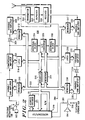
- Mobile radio 112 includes a transmitter 242, receiver 244 and a duplexer 243 for coupling transmitter 242 and receiver 243 to the mobile antenna.
- mobile 120 is a conventional cellular radiotelephone.
- the operation of mobile 120 is controlled by a microcomputer 220 which is coupled by signals 280 to and preferably located in mobile radio 112 (or in any other suitable place, such as, for example, in speakerphone control circuitry 106).
- microcomputer 220 controls operation of speakerphone control circuitry 106.
- Speakerphone control circuitry 106 couples and compresses the transmit audio from auxiliary microphone 102 or the microphone of mobile telephone 108 to transmitter 242 (the “transmit voice path") and couples and expands the receive audio from receiver 244 to auxiliary speaker 104 or the speaker of mobile telephone 108 (the “receive voice path").
- Microcomputer 220 switches between the mobile telephone 108 and the auxiliary microphone 102 and speaker 104 depending on whether the mobile user has selected the hands-free mode of operation. According to the present invention, when the mobile user has selected the hands-free mode of operation, microcomputer 220 is coupled to speakerphone control circuitry 106 for digitally sampling compressed audio and controlling voice path gain switching to produce duplex hands free communications.
- speakerphone control circuitry 106 includes switch 201, variable gain amplifier 202, compressor amplifier 203, switch 204 and variable gain amplifier 205.
- Microcomputer 220 digitally controls switch 201, variable gain amplifier 202, switch 204 and variable gain amplifier 205 by means of data loaded by microcomputer 220 into registers 212 and 213.
- Switch 201 is responsive to a bit from register 212 for selecting between auxiliary microphone 102 and the microphone of mobile telephone 108.
- Variable gain amplifier 202 is responsive to four bits from register 212 for selecting one of sixteen possible gain settings.
- Compressor amplifier is responsive to six bits from latch 218 for selecting one of sixty-four possible gain settings.
- compressor amplifier 203 is similar to the compressor amplifier described in U.S. patent no. 4,550,426, incorporated herein by reference thereto.
- Switch 204 is responsive to a bit from register 213 for opening or closing the transmit voice path.
- Variable gain amplifier 205 is responsive to three bits from register 213 for selecting one of eight possible gain settings.
- speakerphone control circuitry 106 includes variable gain amplifier 232, expander amplifier 233, switch 234, variable gain amplifier 235 and switch 236.
- Microcomputer 220 digitally controls variable gain amplifier 232, switch 234 and variable gain amplifier 235 by means of data loaded by microcomputer 220 into registers 216 and 217.
- Variable gain amplifier 232 is responsive to three bits from register 217 for selecting one of eight possible gain settings.
- Expander amplifier 233 is responsive to six bits from latch 219 for selecting one of sixty-four possible gain settings. In the preferred embodiment, expander amplifier 233 is similar to the expander amplifier described in U.S. patent no. 4,550,426.
- Switch 234 is responsive to a bit from register 216 for opening or closing the receive voice path.
- Variable gain amplifier 235 is responsive to four bits from register 216 for selecting one of sixteen possible gain settings.
- Switch 236 is responsive to signal 281 from microcomputer 220 for selecting between auxiliary speaker 104 and the speaker of mobile telephone I08.
- Speakerphone control circuitry 106 also includes rectifier/filter 224, analog-to-digital (A/D) converter 225 and rectifier/filter 226.
- Rectifier/filter 224 includes a rectifier and filter for filtering the output of compressor amplifier 203.
- Rectifier/filter 226 includes a rectifier and filter for filtering the input of expander amplifier 233.
- A/D converter 225 is preferably a companding or logarithmic six-bit conventional analog-to-digital converter for converting samples of the outputs of rectifier/filters 224 and 226 to a six-bit digital value which is loaded into register 215.
- A/D converter 225 is coupled to latch 218, compressor amplifier 203 and rectifier/filter 224 for producing 2:1 compression of the transmit audio and is coupled to latch 219, expander amplifier 233 and rectifier/filter 226 for producing 1:2 expansion of the receive audio. Under control of microcomputer 220, A/D converter 225 also alternately samples on a continuous basis the outputs of rectifier/filters 224 and 226. Microcomputer 220 may access the digital output of A/D converter 225 by reading the data in register 215. Microcomputer 220 loads data bits C0, C1 and C2 into control register 214 for selecting between the outputs of rectifier/filters 224 and 226.
- speakerphone control circuitry 106 is implemented on a custom integrated circuit and includes additional circuitry and registers for several other functions.
- Microcomputer 220 accesses registers 212-217 by means of a data bus 222 including address, control and data lines.
- microcomputer 220 is a Motorola type 68HC11 microcomputer which is included in mobile radio 112.
- the address of speakerphone control circuitry 106 may be decoded by a conventional binary decoder 221 which produces six chip select CS signals for selecting the seven registers 212-217.
- Microcomputer 220 controls whether data is read from or written into registers 212-217 by means of the read/write R/W signal, which has a binary one state for reading data from a register and a binary zero state for writing data into a register.
- FIG. 3 there is illustrated a register bit map showing the addresses and data bit assignments for each of the registers 212-217.
- the four low order bits of the address for the speakerphone control circuitry 106 determine which register 212-217 is selected.
- the control register 214 has binary address zero
- the A/D register 215 has binary address two
- the TX output register 213 has binary address 4
- the TX input register 212 has binary address 7
- the RX output register 216 has binary address 6
- the RX input register 217 has binary address 5.
- Other addresses are associated with other registers for other functions. If the R/W signal has a binary one state, data is read from the addressed register, and if the R/W signal has a binary zero state, data is written into the addressed register.
- microcomputer 220 utilizes digital samples from A/D converter 225 to continuously generate and store in its memory an envelope signal for the transmit voice path and an envelope signal for receive voice path.
- Microcomputer 220 also produces a valley signal for each path by storing delayed envelope signals.
- microcomputer 220 compares the envelope signal to the valley signal to detect the presence of voice signals and, if the voice activity is detected for a pre-selected time, the gain of the path in which voice signals have been detected is increased and the gain of the other path is decreased.
- Gain in the voice paths may be adjusted by using switch 204 and variable gain amplifier 202 in the transmit voice path and by using switch 234 and variable gain amplifier 235 in the receive voice path.
- Variable gain amplifiers 202 and 235 provide for a gain variation of up to 20 dB with a typical variation of 15 dB for duplex operation, and switches 204 and 234 provide for a gain variation of greater than 60 dB.
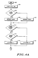
- microcomputer 220 is programmed according to the process steps in Figures 4A, 4B, 5A, 5B, 6 and 7 for dynamically detecting audio signals and switching audio path gain.
- microcomputer 220 enters at start block 402 and proceeds to block 404 where the receive envelope signal LTLEVEL is set to be equal to the digital sample EXP_RAM from A/D converter 225.
- Digital sample EXP_RAM is read by microcomputer 220 from register 215.
- microcomputer 220 loads control register 214 with data for selecting rectifier/filter 226.
- LTLEVEL is compared to the receive valley signal LTVALLEY.
- LTLEVEL is greater than LTVALLEY
- YES branch is taken to block 408 where LTVALLEY is incremented by a pre-selected amount, which in the preferred embodiment is one count per 75 msec. If LTLEVEL is not greater than LTVALLEY, NO branch is taken to block 410 where LTVALLEY is decremented by a pre-selected amount, which in the preferred embodiment is one count per 3 msec.
- LTLEVEL is compared to the receive threshold LTTHRESH plus LTVALLEY.
- LTTHRESH corresponds to the minimum level that the receive signal must rise above the receive valley signal to be considered valid audio or voice.
- the value of LTTHRESH is determined by empirical measurements. If LTLEVEL is not greater than LTTHRESH+LTVALLEY, NO branch is taken to block 418 where the receive comparator flag LTCOMP is set to a binary zero. If LTLEVEL is greater than LTTHRESH+LTVALLEY, YES branch is taken to decision block 414 where a check is made to determine if a false LTLEVEL has been received.
- a false LTLEVEL is determined by comparing LTLEVEL to the current value of the transmit envelope signal MTLEVEL. If LTLEVEL is less than MTLEVEL, YES branch is taken to block 418 to set LCOMP to a binary zero. Otherwise, NO branch is taken to block 416 where LTCOMP is set to a binary one. LTCOMP is set to a binary one to indicate that voice signals have been detected in the receive voice path.
- a check is made to determine if LTCOMP is a binary zero. If LTCOMP is a binary zero, YES branch is taken to decision block 422 where a check is made to determine if the receive variable hold time LTVHT is zero. If so, YES branch is taken to block 424 where the receive pulse width LTPW is set to zero. If LTVHT is not zero, NO branch is taken to block 426 where LTVHT is decremented by one. Then, at decision block 428, a check is made to determine if LTVHT is zero.
- LTVHT is zero
- YES branch is taken to block 430 where the threshold of the transmit voice path MTTHRESH is lowered to increase the audio sensitivity of the transmit voice path. If LTVHT is not zero, NO branch is taken to block 502 in Figure 5A.
- LTCOMP is not a binary zero
- NO branch is taken to decision block 432 where a check is made to determine if LTPW is greater than the maximum pulse width LTPWMAX. If so, YES branch is taken to block 438 where the threshold of the transmit voice path MTTHRESH is raised to reduce the audio sensitivity of the transmit voice path. If LTPW is not greater than LTPWMAX, NO branch is taken to block 434 where LTPW is incremented by one. Then, at decision block 436, a check is made to determine if LTPW is greater than the receive variable hold time delay LTVHTDLY.
- LTVHTDLY is the minimum amount of time that a receive voice signal needs to be present in order for it to be considered valid voice. If not, NO branch is taken to block 502 in Figure 5A. If LTPW is greater than LTVHTDLY, YES branch is taken from decision block 436 to block 438 where the threshold of the transmit voice path is raised. Next, at decision block 440, a check is made to determine if LTVHT is less than the receive variable hold time long LTVHTLNG. LTVHTLNG is the maximum amount of time that the receive voice path can be held after a voice signal is no longer detected. If LTVHT is less than LTVHTLNG, YES branch is taken to block 442 to increment LTVHT by one. Otherwise, NO branch is taken to block 502 in Figure 5A.
- microcomputer 220 now processes the digital sample from A/D converter 225 COMP_RAM for the transmit voice path.
- the transmit envelope signal MTLEVEL is set to be equal to the digital sample COMP_RAM from A/D converter 225.
- Digital sample COMP_RAM is read by microcomputer 220 from register 215. Prior to reading register 215, microcomputer 220 loads control register 214 with data for selecting rectifier/filter 224.
- MTLEVEL is compared to the transmit valley signal MTVALLEY.
- MTLEVEL is greater than MTVALLEY
- YES branch is taken to block 506 where MTVALLEY is incremented by a pre-selected amount, which in the preferred embodiment is one count per 75 msec. If MTLEVEL is not greater than MTVALLEY, NO branch is taken to block 508 where MTVALLEY is decremented by a pre-selected amount, which in the preferred embodiment is one count per 3 msec.
- MTLEVEL is compared to the transmit threshold MTTHRESH plus MTVALLEY.
- MTTHRESH corresponds to the minimum level that the transmit signal must rise above the transmit valley signal to be considered valid audio or voice.
- the value of MTTHRESH is determined by empirical measurements. If MTLEVEL is greater than MTTHRESH+MTVALLEY, YES branch is taken to block 512 to set MTCOMP to a binary one. Otherwise, NO branch is taken to block 514 where MTCOMP is set to a binary zero. MTCOMP is set to a binary one to indicate that voice signals have been detected in the transmit voice path.
- a check is made to determine if MTCOMP is a binary zero. If MTCOMP is a binary zero, YES branch is taken to decision block 518 where a check is made to determine if the transmit variable hold time MTVHT is zero. If so, YES branch is taken to block 520 where the transmit pulse width MTPW is set to zero. If MTVHT is not zero, NO branch is taken to block 522 where MTVHT is decremented by one. Then, at decision block 524, a check is made to determine if MTVHT is zero.
- MTVHT is zero
- YES branch is taken to block 526 where the threshold of the receive voice path LTTHRESH is lowered to increase the audio sensitivity in the receive voice path. If MTVHT is not zero, NO branch is taken to block 602 in Figure 6.
- MTCOMP is not a binary zero
- NO branch is taken to decision block 528 where a check is made to determine if MTPW is greater than the maximum pulse width MTPWMAX. If so, YES branch is taken to block 534 where the threshold of the receive voice path LTTHRESH is raised to reduce the audio sensitivity in the receive voice path. If MTPW is not greater than MTPWMAX, NO branch is taken to block 530 where MTPW is incremented by one. Then, at decision block 532, a check is made to determine if MTPW is greater than the transmit variable hold time delay MTVHTDLY.
- MTVHTDLY is the minimum amount of time that a transmit voice signal needs to be present in order for it to be considered valid voice. If not, NO branch is taken to block 602 in Figure 6. If MTPW is greater than MTVHTDLY, YES branch is taken from decision block 532 to block 534 where the threshold of the receive voice path LTTHRESH is raised. Next, at decision block 536, a check is made to determine if MTVHT is less than the transmit variable hold time long MTVHTLNG. MTVHTLNG is the maximum amount of time that the transmit voice path can be held after a voice signal is no longer detected. If MTVHT is less than MTVHTLNG, YES branch is taken to block 538 to increment MTVHT by one. Otherwise, NO branch is taken to block 602 in Figure 6.
- microcomputer 220 now processes the LTVHT and MTVHT signals to determine gain switching in the receive and transmit voice paths.
- a check is made to determine if LTVHT is greater than zero. If so, YES branch is taken to block 604 where LTDETECT is set to a binary one. If not, NO branch is taken to block 606 where LTDETECT is set to a binary zero. LTDETECT is a binary one when valid voice signals are detected in the receive voice path.
- a check is made to determine if MTVHT is greater than zero. If so, YES branch is taken to block 610 where MTDETECT is set to a binary one. If not, NO branch is taken to block 612 where MTDETECT is set to a binary zero. MTDETECT is a binary one when valid voice signals are detected in the transmit voice path.
- MT.LT is not a binary one
- NO branch is taken to block 710 where the transmitter gain is lowered by 15 dB using variable gain amplifier 202. Then, at block 712, the receiver gain is set to its nominal level using variable gain amplifier 235 and program control returns to other tasks at block 724.
- MT.LT is a binary one. If MT.LT is a binary one, YES branch is taken to block 716 where the receive voice path is muted using switch 234. Then, at block 718, the transmit voice path is unmuted using switch 204 and program control returns to other tasks at block 724. If MT.LT is not a binary one, NO branch is taken from decision block 714 to block 720 where the transmit voice path is muted using switch 204. Then, at block 722, the receive voice path is unmuted using switch 234 and program control returns to other tasks at block 724.
- a unique speakerphone for mobile radiotelephones has been described that digitally samples compressed audio and digitally controls voice path gain.
- the speakerphone of the present invention uses a companding analog-to-digital converter for digitally sampling the signals in each voice path and registers for digitally controlling voice path gain. Since speakerphone operation is controlled by a microcomputer, operational parameters may be easily adjusted to meet the needs of a particular application. Therefore, while a particular embodiment of the present invention has been shown and described, it should be understood that the present invention is not limited thereto since other embodiments may be made by those skilled in the art.
Landscapes
- Engineering & Computer Science (AREA)
- Signal Processing (AREA)
- Mobile Radio Communication Systems (AREA)
- Reduction Or Emphasis Of Bandwidth Of Signals (AREA)
- Tone Control, Compression And Expansion, Limiting Amplitude (AREA)
Applications Claiming Priority (2)
| Application Number | Priority Date | Filing Date | Title |
|---|---|---|---|
| US07/042,143 US4741018A (en) | 1987-04-24 | 1987-04-24 | Speakerphone using digitally compressed audio to control voice path gain |
| US42143 | 1987-04-24 |
Publications (3)
| Publication Number | Publication Date |
|---|---|
| EP0288078A2 true EP0288078A2 (de) | 1988-10-26 |
| EP0288078A3 EP0288078A3 (en) | 1989-05-31 |
| EP0288078B1 EP0288078B1 (de) | 1995-01-04 |
Family
ID=21920260
Family Applications (1)
| Application Number | Title | Priority Date | Filing Date |
|---|---|---|---|
| EP88106502A Expired - Lifetime EP0288078B1 (de) | 1987-04-24 | 1988-04-22 | Lauthörfernsprechgerät mit digital komprimiertem Tonanteil zwecks Regelung der Sprachkanalverstärkung |
Country Status (9)
| Country | Link |
|---|---|
| US (1) | US4741018A (de) |
| EP (1) | EP0288078B1 (de) |
| AR (1) | AR241476A1 (de) |
| AT (1) | ATE116783T1 (de) |
| BR (1) | BR8801869A (de) |
| DE (1) | DE3852666T2 (de) |
| ES (1) | ES2065897T3 (de) |
| HK (1) | HK46297A (de) |
| IL (1) | IL85191A (de) |
Cited By (4)
| Publication number | Priority date | Publication date | Assignee | Title |
|---|---|---|---|---|
| DE4130045A1 (de) * | 1991-09-10 | 1993-03-18 | Standard Elektrik Lorenz Ag | Schaltungsanordnung zur dynamiksteuerung eines sprachendgeraetes |
| EP0615397A3 (de) * | 1993-03-11 | 1994-10-19 | Nec Corp | Schaltung zur Rauschverminderung für das Mikrofon eines Funkgerätes. |
| WO2002021807A3 (en) * | 2000-09-07 | 2002-05-16 | Simoco Int Ltd | Echo reduction in two-way communication |
| DE19526749B4 (de) * | 1994-08-02 | 2006-06-29 | Motorola, Inc., Schaumburg | Schaltkreis und Verfahren zur Verringerung von Eigenecho in einem Empfangssignalpfad |
Families Citing this family (63)
| Publication number | Priority date | Publication date | Assignee | Title |
|---|---|---|---|---|
| US4675863A (en) | 1985-03-20 | 1987-06-23 | International Mobile Machines Corp. | Subscriber RF telephone system for providing multiple speech and/or data signals simultaneously over either a single or a plurality of RF channels |
| JPS63233638A (ja) * | 1987-03-21 | 1988-09-29 | Aisin Seiki Co Ltd | 車載電話装置 |
| US4843621A (en) * | 1987-04-24 | 1989-06-27 | Motorola, Inc. | Speakerphone using digitally compressed audio to detect acoustic feedback |
| US4893286A (en) * | 1987-11-04 | 1990-01-09 | Standard Oil Company | System and method for preprocessing and transmitting echo waveform information |
| US4953147A (en) * | 1987-11-04 | 1990-08-28 | The Stnadard Oil Company | Measurement of corrosion with curved ultrasonic transducer, rule-based processing of full echo waveforms |
| USRE36934E (en) * | 1988-07-19 | 2000-10-31 | Sgs-Thomson Microelectronics S.A. | Control device for a hands-free telephone set |
| US4991197A (en) * | 1988-09-01 | 1991-02-05 | Intelligence Technology Corporation | Method and apparatus for controlling transmission of voice and data signals |
| US4879745A (en) * | 1988-10-12 | 1989-11-07 | Ibm Corporation | Half-duplex speakerphone |
| US4912758A (en) * | 1988-10-26 | 1990-03-27 | International Business Machines Corporation | Full-duplex digital speakerphone |
| FR2641150B1 (de) * | 1988-12-28 | 1991-04-19 | Sgs Thomson Microelectronics | |
| US5278990A (en) * | 1989-10-10 | 1994-01-11 | Motorola, Inc. | Two way radio communication system |
| US5014294A (en) * | 1990-02-01 | 1991-05-07 | Motorola Inc. | Speakerphone for cellular telephones with howl prevention, detection, elimination and determination |
| US5010570A (en) * | 1990-02-20 | 1991-04-23 | Motorola, Inc. | Method for active feedback suppression |
| JPH04152719A (ja) * | 1990-10-16 | 1992-05-26 | Fujitsu Ltd | 音声検出回路 |
| JP2941963B2 (ja) * | 1991-01-17 | 1999-08-30 | キヤノン株式会社 | コードレス電話装置 |
| US5230089A (en) * | 1992-02-03 | 1993-07-20 | Motorola | Automated voice operated transmitter control |
| WO1993019525A1 (en) * | 1992-03-23 | 1993-09-30 | Euphonix, Inc. | Visual dynamics management for audio instrument |
| US5613228A (en) * | 1992-07-06 | 1997-03-18 | Micron Technology, Inc. | Gain adjustment method in two-way communication systems |
| US5357567A (en) * | 1992-08-14 | 1994-10-18 | Motorola, Inc. | Method and apparatus for volume switched gain control |
| US5394476A (en) * | 1992-12-17 | 1995-02-28 | Motorola, Inc. | Volume control device |
| US5546383A (en) * | 1993-09-30 | 1996-08-13 | Cooley; David M. | Modularly clustered radiotelephone system |
| US5467393A (en) * | 1993-11-24 | 1995-11-14 | Ericsson Inc. | Method and apparatus for volume and intelligibility control for a loudspeaker |
| US5761621A (en) | 1993-12-15 | 1998-06-02 | Spectrum Information Technologies, Inc. | Apparatus and methods for networking omni-modal radio devices |
| US6934558B1 (en) * | 1993-12-15 | 2005-08-23 | Mlr, Llc | Adaptive omni-modal radio apparatus and methods |
| US5630205A (en) * | 1994-06-14 | 1997-05-13 | Ericsson Inc. | Mobile phone having voice message capability |
| US5588041A (en) * | 1995-01-05 | 1996-12-24 | Motorola, Inc. | Cellular speakerphone and method of operation thereof |
| US5715309A (en) * | 1995-03-03 | 1998-02-03 | Advanced Micro Devices, Inc. | Conversion of compressed speech codes between attenuated and unattenuated formats |
| JPH08331234A (ja) | 1995-03-24 | 1996-12-13 | Canon Inc | 電話装置 |
| US5845216A (en) * | 1995-05-30 | 1998-12-01 | Sierra Wireless, Inc. | Optimized companding for communication over cellular systems |
| GB2318025B (en) * | 1995-05-31 | 1998-09-02 | Casio Phonemate Inc | Speakerphone, speakerphone system and method of operating speakerphone |
| GB2301731B (en) * | 1995-05-31 | 1998-09-02 | Casio Phonemate Inc | Speakerphone, speakerphone system and method of operating a speakerphone |
| DE19600965C2 (de) * | 1996-01-12 | 2001-08-23 | Siemens Ag | Mobiles Fernsprechendgerät |
| US5966438A (en) * | 1996-03-05 | 1999-10-12 | Ericsson Inc. | Method and apparatus for adaptive volume control for a radiotelephone |
| US5832390A (en) * | 1996-07-03 | 1998-11-03 | Ericsson, Inc. | Untethered microphone and base unit |
| US6978009B1 (en) * | 1996-08-20 | 2005-12-20 | Legerity, Inc. | Microprocessor-controlled full-duplex speakerphone using automatic gain control |
| US5907538A (en) * | 1997-02-18 | 1999-05-25 | White; Donald R. | Full duplex communication circuit with a transducer for simultaneously generating audio output and receiving audio input |
| US7072476B2 (en) * | 1997-02-18 | 2006-07-04 | Matech, Inc. | Audio headset |
| US20080207202A1 (en) * | 1997-07-30 | 2008-08-28 | Zellner Samuel N | Apparatus and method for providing a user interface for facilitating communications between devices |
| US20080195641A1 (en) * | 1997-07-30 | 2008-08-14 | Steven Tischer | Apparatus and method for aggregating and accessing data according to user information |
| US20080194251A1 (en) * | 1997-07-30 | 2008-08-14 | Steven Tischer | Apparatus and method for providing communications and connection-oriented services to devices |
| US20080207197A1 (en) | 1997-07-30 | 2008-08-28 | Steven Tischer | Apparatus, method, and computer-readable medium for interfacing devices with communications networks |
| US7194083B1 (en) | 2002-07-15 | 2007-03-20 | Bellsouth Intellectual Property Corporation | System and method for interfacing plain old telephone system (POTS) devices with cellular networks |
| US20080220776A1 (en) * | 1997-07-30 | 2008-09-11 | Steven Tischer | Interface devices for facilitating communications between devices and communications networks |
| US7149514B1 (en) | 1997-07-30 | 2006-12-12 | Bellsouth Intellectual Property Corp. | Cellular docking station |
| US6411802B1 (en) | 1999-03-15 | 2002-06-25 | Bellsouth Intellectual Property Management Corporation | Wireless backup telephone device |
| US6717980B1 (en) * | 1999-05-24 | 2004-04-06 | Koninklijke Philips Electronics N.V. | Reduction of transmitter induced cross modulation in a receiver |
| AU2001249287A1 (en) | 2000-03-21 | 2001-10-03 | Charles M. Leedom Jr. | A tiered wireless, multi-modal access system and method |
| US7489790B2 (en) * | 2000-12-05 | 2009-02-10 | Ami Semiconductor, Inc. | Digital automatic gain control |
| US6957089B2 (en) * | 2001-05-31 | 2005-10-18 | Coby Electronics Corporation | Compact hands-free adapter for use with a cellular telephone |
| US7242784B2 (en) * | 2001-09-04 | 2007-07-10 | Motorola Inc. | Dynamic gain control of audio in a communication device |
| US7120454B1 (en) * | 2001-12-26 | 2006-10-10 | Bellsouth Intellectual Property Corp. | Auto sensing home base station for mobile telephone with remote answering capabilites |
| US8275371B2 (en) | 2002-07-15 | 2012-09-25 | At&T Intellectual Property I, L.P. | Apparatus and method for providing communications and connection-oriented services to devices |
| US8543098B2 (en) | 2002-07-15 | 2013-09-24 | At&T Intellectual Property I, L.P. | Apparatus and method for securely providing communications between devices and networks |
| US7200424B2 (en) | 2002-07-15 | 2007-04-03 | Bellsouth Intelectual Property Corporation | Systems and methods for restricting the use and movement of telephony devices |
| US8000682B2 (en) * | 2002-07-15 | 2011-08-16 | At&T Intellectual Property I, L.P. | Apparatus and method for restricting access to data |
| US8554187B2 (en) | 2002-07-15 | 2013-10-08 | At&T Intellectual Property I, L.P. | Apparatus and method for routing communications between networks and devices |
| US8416804B2 (en) | 2002-07-15 | 2013-04-09 | At&T Intellectual Property I, L.P. | Apparatus and method for providing a user interface for facilitating communications between devices |
| US8526466B2 (en) | 2002-07-15 | 2013-09-03 | At&T Intellectual Property I, L.P. | Apparatus and method for prioritizing communications between devices |
| WO2005048572A2 (en) * | 2003-11-11 | 2005-05-26 | Matech, Inc. | Two-way communications device having a single transducer |
| US7826805B2 (en) * | 2003-11-11 | 2010-11-02 | Matech, Inc. | Automatic-switching wireless communication device |
| US8315379B2 (en) * | 2004-11-10 | 2012-11-20 | Matech, Inc. | Single transducer full duplex talking circuit |
| US20060136201A1 (en) * | 2004-12-22 | 2006-06-22 | Motorola, Inc. | Hands-free push-to-talk radio |
| KR100780440B1 (ko) * | 2006-09-19 | 2007-11-29 | 삼성전자주식회사 | 휴대 단말기 및 그의 포화 감지를 이용한 음압 조절 방법 |
Family Cites Families (11)
| Publication number | Priority date | Publication date | Assignee | Title |
|---|---|---|---|---|
| US3377559A (en) * | 1965-12-30 | 1968-04-09 | Automatic Elect Lab | Compandoring techniques for high-frequency radio circuits |
| FR2255762B1 (de) * | 1973-12-21 | 1976-07-23 | Ibm France | |
| US4123711A (en) * | 1977-01-24 | 1978-10-31 | Canadian Patents And Development Limited | Synchronized compressor and expander voice processing system for radio telephone |
| FR2454231A1 (fr) * | 1979-04-13 | 1980-11-07 | Thomson Csf | Emetteur-recepteur a commande automatique d'alternat et reseau de telecommunications comportant un tel emetteur-recepteur |
| US4378603A (en) * | 1980-12-23 | 1983-03-29 | Motorola, Inc. | Radiotelephone with hands-free operation |
| US4550426A (en) * | 1981-12-31 | 1985-10-29 | Motorola, Inc. | Method and means of detecting the presence of a signal representing voice and of compressing the level of the signal |
| US4400584A (en) * | 1982-04-05 | 1983-08-23 | Motorola, Inc. | Speakerphone for radio and, landline telephones |
| FR2537756B1 (fr) * | 1982-12-10 | 1985-11-08 | Thomson Csf | Dispositif de traitement de la parole pour equipements radioelectriques adaptes a la transmission et a la reception de la parole |
| GB2137458B (en) * | 1983-03-01 | 1986-11-19 | Standard Telephones Cables Ltd | Digital handsfree telephone |
| JPS60101769A (ja) * | 1983-11-09 | 1985-06-05 | Hitachi Ltd | 信号伝送装置 |
| GB2174578B (en) * | 1985-05-04 | 1988-11-09 | Stc Plc | Loud speaking telephone |
-
1987
- 1987-04-24 US US07/042,143 patent/US4741018A/en not_active Expired - Lifetime
-
1988
- 1988-01-25 IL IL85191A patent/IL85191A/xx not_active IP Right Cessation
- 1988-02-09 AR AR88310047A patent/AR241476A1/es active
- 1988-04-20 BR BR8801869A patent/BR8801869A/pt not_active IP Right Cessation
- 1988-04-22 ES ES88106502T patent/ES2065897T3/es not_active Expired - Lifetime
- 1988-04-22 EP EP88106502A patent/EP0288078B1/de not_active Expired - Lifetime
- 1988-04-22 AT AT88106502T patent/ATE116783T1/de active
- 1988-04-22 DE DE3852666T patent/DE3852666T2/de not_active Expired - Fee Related
-
1997
- 1997-04-10 HK HK46297A patent/HK46297A/en not_active IP Right Cessation
Cited By (7)
| Publication number | Priority date | Publication date | Assignee | Title |
|---|---|---|---|---|
| DE4130045A1 (de) * | 1991-09-10 | 1993-03-18 | Standard Elektrik Lorenz Ag | Schaltungsanordnung zur dynamiksteuerung eines sprachendgeraetes |
| US5359653A (en) * | 1991-09-10 | 1994-10-25 | Alcatel N.V. | Circuit arrangement for controlling the volume range of a voice terminal |
| EP0615397A3 (de) * | 1993-03-11 | 1994-10-19 | Nec Corp | Schaltung zur Rauschverminderung für das Mikrofon eines Funkgerätes. |
| US5903853A (en) * | 1993-03-11 | 1999-05-11 | Nec Corporation | Radio transceiver including noise suppressor |
| DE19526749B4 (de) * | 1994-08-02 | 2006-06-29 | Motorola, Inc., Schaumburg | Schaltkreis und Verfahren zur Verringerung von Eigenecho in einem Empfangssignalpfad |
| DE19526749B8 (de) * | 1994-08-02 | 2006-10-19 | Freescale Semiconductor, Inc. (n.d.Ges.d. Staates Delaware), Austin | Schaltkreis und Verfahren zur Verringerung von Eigenecho in einem Empfangssignalpfad |
| WO2002021807A3 (en) * | 2000-09-07 | 2002-05-16 | Simoco Int Ltd | Echo reduction in two-way communication |
Also Published As
| Publication number | Publication date |
|---|---|
| IL85191A (en) | 1991-07-18 |
| BR8801869A (pt) | 1988-11-22 |
| ATE116783T1 (de) | 1995-01-15 |
| AR241476A1 (es) | 1992-07-31 |
| ES2065897T3 (es) | 1995-03-01 |
| IL85191A0 (en) | 1988-07-31 |
| DE3852666T2 (de) | 1995-08-17 |
| DE3852666D1 (de) | 1995-02-16 |
| HK46297A (en) | 1997-04-18 |
| US4741018A (en) | 1988-04-26 |
| EP0288078A3 (en) | 1989-05-31 |
| EP0288078B1 (de) | 1995-01-04 |
Similar Documents
| Publication | Publication Date | Title |
|---|---|---|
| US4741018A (en) | Speakerphone using digitally compressed audio to control voice path gain | |
| US4843621A (en) | Speakerphone using digitally compressed audio to detect acoustic feedback | |
| US4715063A (en) | Speakerphone for radio and landline telephones | |
| EP0067173B1 (de) | Radiotelephon mit freisprechbetrieb | |
| US4400584A (en) | Speakerphone for radio and, landline telephones | |
| KR960003840B1 (ko) | 무선전화장치 및 그 통신방법 | |
| FI88570B (fi) | Telefonkrets som laemnar haenderna fria | |
| JPH0783398B2 (ja) | ハウリングの防止、検出、消去および判定を備えたセルラ電話のためのスピーカホン | |
| US5953674A (en) | Asynchronous serial communications on a portable communication device serial communication bus | |
| AU609527B2 (en) | Method for terminating a telephone call by voice command | |
| US5222251A (en) | Method for eliminating acoustic echo in a communication device | |
| CA1244168A (en) | Speakerphone for radio and landline telephones | |
| KR920015798A (ko) | 무선 전화기용 자동 채널 선택 시스템 | |
| JPH0773387B2 (ja) | 携帯電話装置 | |
| US6154639A (en) | Handsfree unit | |
| KR880001016B1 (ko) | 핸드프리(hand free)작동의 무선전화기 | |
| JP3251177B2 (ja) | エコー低減回路 | |
| JPH10173745A (ja) | カーオーディオ | |
| JPH0748771B2 (ja) | 拡声電話機 | |
| KR19980041438A (ko) | 사용자 음성레벨에 따른 수신음량 자동조정기능을 갖춘 이동단말기 | |
| JPH1075283A (ja) | 通信用携帯端末及びそのノイズ低減方式 | |
| KR100369647B1 (ko) | 핸즈프리 기능 구현을 위한 보코더 및 코덱 이득 제어 방법 | |
| JPH06113004A (ja) | ハンズフリー通話機能を有する携帯子機 | |
| HK13890A (en) | Radiotelephone with hands-free operation | |
| JPH0555951A (ja) | 携帯型電話機のハンズフリー回路 |
Legal Events
| Date | Code | Title | Description |
|---|---|---|---|
| PUAI | Public reference made under article 153(3) epc to a published international application that has entered the european phase |
Free format text: ORIGINAL CODE: 0009012 |
|
| AK | Designated contracting states |
Kind code of ref document: A2 Designated state(s): AT BE CH DE ES FR GB IT LI LU NL SE |
|
| PUAL | Search report despatched |
Free format text: ORIGINAL CODE: 0009013 |
|
| AK | Designated contracting states |
Kind code of ref document: A3 Designated state(s): AT BE CH DE ES FR GB IT LI LU NL SE |
|
| 17P | Request for examination filed |
Effective date: 19891124 |
|
| 17Q | First examination report despatched |
Effective date: 19920312 |
|
| GRAA | (expected) grant |
Free format text: ORIGINAL CODE: 0009210 |
|
| ITF | It: translation for a ep patent filed | ||
| AK | Designated contracting states |
Kind code of ref document: B1 Designated state(s): AT BE CH DE ES FR GB IT LI LU NL SE |
|
| PG25 | Lapsed in a contracting state [announced via postgrant information from national office to epo] |
Ref country code: NL Effective date: 19950104 Ref country code: LI Effective date: 19950104 Ref country code: CH Effective date: 19950104 Ref country code: BE Effective date: 19950104 Ref country code: AT Effective date: 19950104 |
|
| REF | Corresponds to: |
Ref document number: 116783 Country of ref document: AT Date of ref document: 19950115 Kind code of ref document: T |
|
| ET | Fr: translation filed | ||
| REF | Corresponds to: |
Ref document number: 3852666 Country of ref document: DE Date of ref document: 19950216 |
|
| REG | Reference to a national code |
Ref country code: ES Ref legal event code: FG2A Ref document number: 2065897 Country of ref document: ES Kind code of ref document: T3 |
|
| PG25 | Lapsed in a contracting state [announced via postgrant information from national office to epo] |
Ref country code: SE Effective date: 19950404 |
|
| REG | Reference to a national code |
Ref country code: CH Ref legal event code: PL |
|
| PG25 | Lapsed in a contracting state [announced via postgrant information from national office to epo] |
Ref country code: LU Free format text: LAPSE BECAUSE OF NON-PAYMENT OF DUE FEES Effective date: 19950430 |
|
| NLV1 | Nl: lapsed or annulled due to failure to fulfill the requirements of art. 29p and 29m of the patents act | ||
| PLBE | No opposition filed within time limit |
Free format text: ORIGINAL CODE: 0009261 |
|
| STAA | Information on the status of an ep patent application or granted ep patent |
Free format text: STATUS: NO OPPOSITION FILED WITHIN TIME LIMIT |
|
| 26N | No opposition filed | ||
| PGFP | Annual fee paid to national office [announced via postgrant information from national office to epo] |
Ref country code: ES Payment date: 19990419 Year of fee payment: 12 |
|
| PGFP | Annual fee paid to national office [announced via postgrant information from national office to epo] |
Ref country code: GB Payment date: 20000321 Year of fee payment: 13 |
|
| PGFP | Annual fee paid to national office [announced via postgrant information from national office to epo] |
Ref country code: DE Payment date: 20000418 Year of fee payment: 13 |
|
| PG25 | Lapsed in a contracting state [announced via postgrant information from national office to epo] |
Ref country code: ES Free format text: THE PATENT HAS BEEN ANNULLED BY A DECISION OF A NATIONAL AUTHORITY Effective date: 20000424 |
|
| PG25 | Lapsed in a contracting state [announced via postgrant information from national office to epo] |
Ref country code: GB Free format text: LAPSE BECAUSE OF NON-PAYMENT OF DUE FEES Effective date: 20010422 |
|
| GBPC | Gb: european patent ceased through non-payment of renewal fee |
Effective date: 20010422 |
|
| PG25 | Lapsed in a contracting state [announced via postgrant information from national office to epo] |
Ref country code: DE Free format text: LAPSE BECAUSE OF NON-PAYMENT OF DUE FEES Effective date: 20020201 |
|
| REG | Reference to a national code |
Ref country code: ES Ref legal event code: FD2A Effective date: 20020204 |
|
| PGFP | Annual fee paid to national office [announced via postgrant information from national office to epo] |
Ref country code: FR Payment date: 20040402 Year of fee payment: 17 |
|
| PG25 | Lapsed in a contracting state [announced via postgrant information from national office to epo] |
Ref country code: IT Free format text: LAPSE BECAUSE OF NON-PAYMENT OF DUE FEES;WARNING: LAPSES OF ITALIAN PATENTS WITH EFFECTIVE DATE BEFORE 2007 MAY HAVE OCCURRED AT ANY TIME BEFORE 2007. THE CORRECT EFFECTIVE DATE MAY BE DIFFERENT FROM THE ONE RECORDED. Effective date: 20050422 |
|
| PG25 | Lapsed in a contracting state [announced via postgrant information from national office to epo] |
Ref country code: FR Free format text: LAPSE BECAUSE OF NON-PAYMENT OF DUE FEES Effective date: 20051230 |
|
| REG | Reference to a national code |
Ref country code: FR Ref legal event code: ST Effective date: 20051230 |
|
| P01 | Opt-out of the competence of the unified patent court (upc) registered |
Effective date: 20230520 |