EP0288475B1 - Bande transporteuse - Google Patents
Bande transporteuse Download PDFInfo
- Publication number
- EP0288475B1 EP0288475B1 EP87900334A EP87900334A EP0288475B1 EP 0288475 B1 EP0288475 B1 EP 0288475B1 EP 87900334 A EP87900334 A EP 87900334A EP 87900334 A EP87900334 A EP 87900334A EP 0288475 B1 EP0288475 B1 EP 0288475B1
- Authority
- EP
- European Patent Office
- Prior art keywords
- belt
- spacer means
- bottom part
- tier
- edge portion
- Prior art date
- Legal status (The legal status is an assumption and is not a legal conclusion. Google has not performed a legal analysis and makes no representation as to the accuracy of the status listed.)
- Expired
Links
Images

Classifications
-
- B—PERFORMING OPERATIONS; TRANSPORTING
- B65—CONVEYING; PACKING; STORING; HANDLING THIN OR FILAMENTARY MATERIAL
- B65G—TRANSPORT OR STORAGE DEVICES, e.g. CONVEYORS FOR LOADING OR TIPPING, SHOP CONVEYOR SYSTEMS OR PNEUMATIC TUBE CONVEYORS
- B65G21/00—Supporting or protective framework or housings for endless load-carriers or traction elements of belt or chain conveyors
- B65G21/16—Supporting or protective framework or housings for endless load-carriers or traction elements of belt or chain conveyors for conveyors having endless load-carriers movable in curved paths
- B65G21/18—Supporting or protective framework or housings for endless load-carriers or traction elements of belt or chain conveyors for conveyors having endless load-carriers movable in curved paths in three-dimensionally curved paths
-
- B—PERFORMING OPERATIONS; TRANSPORTING
- B65—CONVEYING; PACKING; STORING; HANDLING THIN OR FILAMENTARY MATERIAL
- B65G—TRANSPORT OR STORAGE DEVICES, e.g. CONVEYORS FOR LOADING OR TIPPING, SHOP CONVEYOR SYSTEMS OR PNEUMATIC TUBE CONVEYORS
- B65G17/00—Conveyors having an endless traction element, e.g. a chain, transmitting movement to a continuous or substantially-continuous load-carrying surface or to a series of individual load-carriers; Endless-chain conveyors in which the chains form the load-carrying surface
- B65G17/06—Conveyors having an endless traction element, e.g. a chain, transmitting movement to a continuous or substantially-continuous load-carrying surface or to a series of individual load-carriers; Endless-chain conveyors in which the chains form the load-carrying surface having a load-carrying surface formed by a series of interconnected, e.g. longitudinal, links, plates, or platforms
- B65G17/063—Conveyors having an endless traction element, e.g. a chain, transmitting movement to a continuous or substantially-continuous load-carrying surface or to a series of individual load-carriers; Endless-chain conveyors in which the chains form the load-carrying surface having a load-carrying surface formed by a series of interconnected, e.g. longitudinal, links, plates, or platforms the load carrying surface being formed by profiles, rods, bars, rollers or the like attached to more than one traction element
-
- B—PERFORMING OPERATIONS; TRANSPORTING
- B65—CONVEYING; PACKING; STORING; HANDLING THIN OR FILAMENTARY MATERIAL
- B65G—TRANSPORT OR STORAGE DEVICES, e.g. CONVEYORS FOR LOADING OR TIPPING, SHOP CONVEYOR SYSTEMS OR PNEUMATIC TUBE CONVEYORS
- B65G2201/00—Indexing codes relating to handling devices, e.g. conveyors, characterised by the type of product or load being conveyed or handled
- B65G2201/06—Articles and bulk
-
- B—PERFORMING OPERATIONS; TRANSPORTING
- B65—CONVEYING; PACKING; STORING; HANDLING THIN OR FILAMENTARY MATERIAL
- B65G—TRANSPORT OR STORAGE DEVICES, e.g. CONVEYORS FOR LOADING OR TIPPING, SHOP CONVEYOR SYSTEMS OR PNEUMATIC TUBE CONVEYORS
- B65G2207/00—Indexing codes relating to constructional details, configuration and additional features of a handling device, e.g. Conveyors
- B65G2207/24—Helical or spiral conveying path
Definitions
- the present invention relates to a conveyor belt which is adapted in endless design to follow, through part of its length, a path comprising a number or superimposed, helically extending tiers forming a belt pile.
- Such a conveyor belt is previously known from SE patent 381,241 and SE patent application 8206760-4 (SE-B-437008) and consists of mutually articulated and relatively adjustable link means, each comprising a bottom part and spacer means arranged at the longitudinal edges of said bottom part, said spacer means forming the two sides of the belt and being adapted, with their upper edge portions, to bear against the lower edge portions of the overlying tier of the conveyor belt.
- each belt tier is supported by an underlying belt tier and supports itself an overlying belt tier.
- At least a part of the spacer means according to the SE patent are adapted to engage shoulders at the lower edge portions of said spacer members on at least one side of the overlying tier of the conveyor belt.
- the above conveyor belt constructions constitute an obstacle in so far as the risk that the belt pile may collapse will quickly exceed permissible limits.
- higher strength and rigidity may be obtained by increasing the dimensions of the parts included in the link means, this will also increase the weight of the conveyor belt, resulting in such an increased load on the bottom tier of the belt pile that the entire belt pile tends to collapse.
- the construction according to the invention precludes any possibility of an undesired lateral relative displacement of the belt tiers in the belt pile, and this is accomplished by the mutual positive guiding in the lateral direction between the spacer means in superimposed belt tiers.
- the present invention pays regard to the fact that one important cause of a collapse is the tensile force which is generated in the conveyor belt by the friction in the return path from the point where the belt leaves the belt pile to the point where it reenters the pile.
- the tensile force strives to contract the lowermost belt tier which, however, normally is held in position by an internal supporting ring.
- the tensile force must then be absorbed completely by the first belt tier free from the supporting ring.
- the conveyor belt construction according to the invention makes the belt pile act essentially as a single stable drum which thus is able, via several belt tiers, to absorb the belt tension caused by said tensile force and to effectively prevent contraction of the belt pile immediately above the supporting ring.
- the link means positioned in superimposed belt tiers will be firmly interengaged, at least on the outer side of the belt pile, in contrast to the loose interengagement of the prior art constructions. In this manner, the strength of the belt pile could be increased many times over.
- the invention makes it possible to use the same basic material, i.e. in respect of thickness, for manufacturing the components of the link means, irrespective of the width and height of the belt and the number of tiers in the pile, and this is a considerable advantage from the viewpoint of manufacture.
- Fig. 1 is a perspective view of a conveying device for which the conveyor belt according to the invention is intended.
- Fig. 2 is a schematic cross-sectional view of the link means of two belt tiers, and Fig. 3 shows a part of the conveyor belt from above.
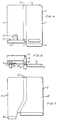
- Fig. 4 is a lateral view of an embodiment of a spacer means according to the invention.
- Figs. 5 and 6 show the spacer means in Fig. 4 as seen in the longitudinal direction of the conveyor belt and from below, respectively.
- Fig. 7 is a view, corresponding to Fig. 4, of a second embodiment of a spacer means according to the invention.
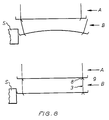
- Fig. 8 illustrates schematically the deformation of link means adjacent a supporting ring.
- An endless conveyor belt 1 intended, for example, for a conveying device of the type illustrated in Fig. 1 is adapted to follow, in the manner illustrated, through part of its length a path comprising a number of superimposed helically extending tiers.
- the conveyor belt 1, partially illustrated in Figs. 2 and 3 comprises a number of mutually articulated and relatively adjustable link means consisting of a bottom part 2 and, disposed at the ends thereof, links 3 which form the two sides of the conveyor belt and, at the same time, are designed as spacer means, the upper edge portions 4 of which bear against the lower edge portions of the spacer means of the overlying belt tier and thus support the overlying belt tier via the respective edge portions.
- the bottom part 2 consists of transverse rod-shaped connecting elements 5 for the links 3.
- These connecting elements 5 may be coated with wire, netting or the like to serve as a supporting plane and permit adjustment of the link means by mutual displacement thereof in the longitudinal direction of the belt 1.
- the spacer means or links 3 are through a part 6 of their length fixedly connected to the longitudinal edges of the bottom part 2. In the embodiment illustrated, this is achieved in that they are fixedly connected with two of the rod-shaped elements 5 which are spaced apart in the longitudinal direction of the belt.
- the remaining part 7 of the spacer means 3, which extends in the longitudinal direction beyond the said two rod-shaped elements 5, is movable relative to the bottom part 2 and provided with a downwardly and inwardly inclined flange 8.
- the flanges 8 of the successive spacer means 3 form inner shoulders engaging the inner side of the upper edge portion 4 of the spacer means 3 of the underlying belt tier.
- the lower portion 9 of the part 6 is inclined in a downward and outward direction and continues in a further outwardly angled portion 10 extending essentially perpendicular to the belt side.
- the inclined portions 9 of the successive links 3 thus form outer shoulders engaging the outer side of the upper edge portion 4 of the spacer means 3 of the underlying belt tier. In this manner, the upper edge portion 4 is positively guided in the lateral direction between the oppositely directed shoulders formed by the flanges 8 and the inclined portions 9 arranged alternately in the longitudinal direction of the belt.
- supporting means are fixedly arranged on the inner side of the inclined portions 9 having a supporting surface 11 essentially perpendicular to the belt side.
- the supporting surface 11 is suitably formed by the bottom part 2 and may preferably consist of the underside of the rod-shaped elements 5 which, in the embodiment illustrated, extend through holes in the inclined portion 9 to engage with their outer end the upper side of the portions 10, for example by welding.
- each spacer means 3 which is fixed relative to the bottom part 2, is slightly laterally displaced relative to the movable part 7, the part 6 being arranged to overlap on the outer side the part 7 of the adjacent spacer means.
- the part 7 also has an oblong hole to receive an elongated element associated with an adjacent spacer means, and to facilitate adjustment of the link means relative to one another by longitudinal displacement of the part 6 of a spacer means in relation to the part 7 of an adjacent spacer means.
- the transition between the parts 6 and 7 is straight, but may also have the curved shape illustrated at 12′ in Fig. 7 where the inclined portion of the part 6′ is longer than the flange 8′ of the part 7′.
- the part 7′ has no oblong hole since the spacer means according to Fig. 7 is suitable for entirely straight belt conveyors or preferably is arranged in the outer curve when the conveyor travels through a curve.
- a spacer means 3′ according to Fig. 7 may be combined with the spacer means 3 according to Figs. 4-6.
- transition 12, 12′ contributes to increasing the rigidity of the spacer means 3 and 3′, respectively.
- An increased flexural rigidity in the connection between the spacer means 3 and the bottom part 2 is achieved by means of a vertical ridge 13 formed in the lower portion of the part 6.
- the spacer means 3 on the outer side of the belt pile are formed in the manner described above, with the shoulders 8, 9 for engagement with both the inner side and the outer side of the upper edge portion 4 of the spacer means 3 of the underlying belt tier, while the spacer means 3 on the inner side of the belt pile merely require the shoulders 8 for engagement with the inner side (as seen toward the center of the belt) of the upper edge portion 4 of the spacer means 3 of the underlying belt tier.
- FIG. 8 a schematic section radially through two tiers of a conveyor belt according to prior art technique is shown, while the bottom of this Figure shows the same section for a conveyor belt according to the present invention. It will be evident that, in the conveyor belt according to prior art technique, the load on a belt tier A above a belt tier B engaging an inner supporting ring S causes a deformation of the link means of the belt tier B, such that the belt pile may collapse because the belt tier A partially drops into the belt tier B.
- the shoulders 8 and 9 need not be longitudinally displaced relative to one another, although such displacement is preferred because it makes it possible to manufacture the spacer means 3 in a single piece from a simple sheet-metal blank.
Landscapes
- Engineering & Computer Science (AREA)
- Mechanical Engineering (AREA)
- Belt Conveyors (AREA)
- Structure Of Belt Conveyors (AREA)
- Chain Conveyers (AREA)
- Semiconductor Integrated Circuits (AREA)
- General Details Of Gearings (AREA)
Abstract
Claims (6)
Applications Claiming Priority (2)
| Application Number | Priority Date | Filing Date | Title |
|---|---|---|---|
| SE8506136 | 1985-12-27 | ||
| SE8506136A SE452590B (sv) | 1985-12-27 | 1985-12-27 | Transportband |
Publications (2)
| Publication Number | Publication Date |
|---|---|
| EP0288475A1 EP0288475A1 (fr) | 1988-11-02 |
| EP0288475B1 true EP0288475B1 (fr) | 1992-03-04 |
Family
ID=20362606
Family Applications (1)
| Application Number | Title | Priority Date | Filing Date |
|---|---|---|---|
| EP87900334A Expired EP0288475B1 (fr) | 1985-12-27 | 1986-12-22 | Bande transporteuse |
Country Status (9)
| Country | Link |
|---|---|
| US (1) | US4941567A (fr) |
| EP (1) | EP0288475B1 (fr) |
| JP (1) | JPH07100524B2 (fr) |
| AU (1) | AU589737B2 (fr) |
| BR (1) | BR8607236A (fr) |
| DE (1) | DE3684156D1 (fr) |
| SE (1) | SE452590B (fr) |
| SU (1) | SU1746877A3 (fr) |
| WO (1) | WO1987004136A1 (fr) |
Families Citing this family (22)
| Publication number | Priority date | Publication date | Assignee | Title |
|---|---|---|---|---|
| SE459726B (sv) * | 1988-07-26 | 1989-07-31 | Frigoscandia Contracting Ab | Transportanordning |
| SE469752B (sv) * | 1989-06-27 | 1993-09-06 | Frigoscandia Food Process Syst | Transportband foer luftbehandlingsanlaeggning daer traadnaetet utgoers av sicksackformade traadar |
| WO1991004209A1 (fr) * | 1989-09-12 | 1991-04-04 | Ashworth Bros., Inc. | Bande de manutention a plaques d'empilage |
| US5247810A (en) * | 1992-07-14 | 1993-09-28 | Liquid Carbonic Corporation | Freezer conveyor |
| US5346057A (en) * | 1992-10-30 | 1994-09-13 | Philip Morris Incorporated | Conveyor belt for treatment of particulate solid material |
| US5335590A (en) * | 1992-10-30 | 1994-08-09 | Philip Morris Incorporated | Apparatus for treatment of solid material |
| US5526581A (en) * | 1992-10-30 | 1996-06-18 | Philip Morris Incorporated | Process for adjusting the moisture content of organic materials |
| US5350056A (en) * | 1993-06-16 | 1994-09-27 | Cambridge, Inc. | Self-supporting conveyor belt with wire-formed spacers |
| US5460260A (en) * | 1994-06-22 | 1995-10-24 | York International Corporation | Helical conveyor |
| SE505637C2 (sv) * | 1995-10-24 | 1997-09-22 | Frigoscandia Equipment Ab | Transportband |
| US5702245A (en) * | 1996-03-20 | 1997-12-30 | Stein, Inc. | Conveyor for processing equipment having gas flow compensation |
| US5803232A (en) * | 1996-09-06 | 1998-09-08 | Frigoscandia Equipment Ab | Conveyor belt |
| NL1011199C1 (nl) * | 1998-04-28 | 1999-10-29 | Stork Titan Bv | Behandelingsinrichting voor het met geconditioneerde lucht behandelen van voedselproducten. |
| US5974692A (en) * | 1998-05-06 | 1999-11-02 | Frigoscandia Equipment Ab | Apparatus for air-treatment of products |
| US6418834B1 (en) * | 1999-07-26 | 2002-07-16 | Paul M. Perrine | Apparatus for treating an item during travel of the item along a treating trough |
| US6796420B2 (en) | 2001-10-23 | 2004-09-28 | Richard K. Byrne | Self-stacking conveyor belt and method |
| US6695128B2 (en) * | 2002-07-18 | 2004-02-24 | Kvp Falcon Plastic Belting, Inc. | Stacked spiral modular plastic conveyor belt system |
| US7258226B2 (en) * | 2003-10-14 | 2007-08-21 | The Boc Group, Inc. | Self-stacking spiral conveyor with modular drive system |
| US7492259B2 (en) * | 2005-03-29 | 2009-02-17 | Accu-Sort Systems, Inc. | RFID conveyor system and method |
| US7270231B2 (en) * | 2005-05-26 | 2007-09-18 | Heber Gerald J | Self-stacking spiral conveyor belt |
| KR20120091048A (ko) * | 2009-09-04 | 2012-08-17 | 라이트람, 엘엘씨 | 스파이럴 컨베이어 시스템 및 방법 |
| SE1051354A1 (sv) * | 2010-12-21 | 2012-06-19 | John Bean Technologies Ab | Förbättrat sidoplattelement för ett länkorgan i ett självstaplande ändlöst transportband |
Family Cites Families (8)
| Publication number | Priority date | Publication date | Assignee | Title |
|---|---|---|---|---|
| SE381241B (sv) * | 1973-03-07 | 1975-12-01 | Frigoscandia Contracting Ab | Transportanordning med ett endlost transportband vilket er anordnat att till en del av sin lengd folja en bana bestaende av ett antal over varandra belegna skruvformigt forlopande varv |
| JPS5127065A (en) * | 1974-08-28 | 1976-03-06 | Hitachi Ltd | Handotaikibanheno gariumusentakukakusanhoho |
| JPS5145951A (ja) * | 1974-10-17 | 1976-04-19 | Nippon Denso Co | Uindokonpareeta |
| US4036352A (en) * | 1975-07-30 | 1977-07-19 | Alto Corporation | Endless conveyor |
| FR2503106B1 (fr) * | 1981-04-03 | 1986-04-18 | Frigofrance Sa | Transporteur a bande sans fin decrivant un helicoide |
| SE434728B (sv) * | 1982-11-26 | 1984-08-13 | Frigoscandia Contracting Ab | Upplagsanordning for uppberande av ett antal det ena over det andra i stapel belegna skruvformigt forlopande varv av ett endlost transportband |
| SE437008B (sv) * | 1982-11-26 | 1985-02-04 | Frigoscandia Contracting Ab | Transportband |
| US4741430A (en) * | 1985-09-27 | 1988-05-03 | Ashworth Bros., Inc. | Positive drive helical conveyor system |
-
1985
- 1985-12-27 SE SE8506136A patent/SE452590B/sv not_active IP Right Cessation
-
1986
- 1986-12-22 EP EP87900334A patent/EP0288475B1/fr not_active Expired
- 1986-12-22 US US07/209,683 patent/US4941567A/en not_active Expired - Lifetime
- 1986-12-22 WO PCT/SE1986/000582 patent/WO1987004136A1/fr not_active Ceased
- 1986-12-22 BR BR8607236A patent/BR8607236A/pt not_active IP Right Cessation
- 1986-12-22 JP JP62500503A patent/JPH07100524B2/ja not_active Expired - Lifetime
- 1986-12-22 AU AU68317/87A patent/AU589737B2/en not_active Expired
- 1986-12-22 DE DE8787900334T patent/DE3684156D1/de not_active Expired - Lifetime
-
1988
- 1988-06-27 SU SU884356070A patent/SU1746877A3/ru active
Also Published As
| Publication number | Publication date |
|---|---|
| AU6831787A (en) | 1987-07-28 |
| WO1987004136A1 (fr) | 1987-07-16 |
| SE452590B (sv) | 1987-12-07 |
| DE3684156D1 (de) | 1992-04-09 |
| JPH07100524B2 (ja) | 1995-11-01 |
| AU589737B2 (en) | 1989-10-19 |
| US4941567A (en) | 1990-07-17 |
| SE8506136D0 (sv) | 1985-12-27 |
| EP0288475A1 (fr) | 1988-11-02 |
| BR8607236A (pt) | 1988-11-01 |
| JPS63502500A (ja) | 1988-09-22 |
| SU1746877A3 (ru) | 1992-07-07 |
| SE8506136L (sv) | 1987-06-28 |
Similar Documents
| Publication | Publication Date | Title |
|---|---|---|
| EP0288475B1 (fr) | Bande transporteuse | |
| US4603776A (en) | Conveyor belt | |
| EP2655223B1 (fr) | Elément de plaque latéral amélioré pour un maillon inclus dans un transporteur à courroie sans fin à auto-empilement | |
| US4577841A (en) | Bent wire spring unit | |
| US9475642B2 (en) | Variable spaced conveyor belt with clinched rod ends | |
| US6382405B1 (en) | Solid top radius conveyor belt | |
| US5190143A (en) | Conveyor belt | |
| JPS6341804B2 (fr) | ||
| US5423416A (en) | Conveyor belts with spiral overlay | |
| US5350056A (en) | Self-supporting conveyor belt with wire-formed spacers | |
| EP1010648A1 (fr) | Convoyeur pour articles | |
| US4754871A (en) | Wire mesh belt and splicer | |
| US4143500A (en) | End bearing construction for truss | |
| DE4037659A1 (de) | Rinnenschuss fuer kettenkratzfoerderer, insbesondere fuer den bergbaueinsatz | |
| US6796420B2 (en) | Self-stacking conveyor belt and method | |
| WO1991004209A1 (fr) | Bande de manutention a plaques d'empilage | |
| RU2029039C1 (ru) | Балка селиванова н.п. | |
| WO1987004747A1 (fr) | Section en feuille metallique destinee en particulier a des structures de plafond, de paroi ou de plancher | |
| JPS60500618A (ja) | ベルトコンベヤ−装置 | |
| NZ215354A (en) | Pallet frame construction;channel sections welded together |
Legal Events
| Date | Code | Title | Description |
|---|---|---|---|
| PUAI | Public reference made under article 153(3) epc to a published international application that has entered the european phase |
Free format text: ORIGINAL CODE: 0009012 |
|
| 17P | Request for examination filed |
Effective date: 19880430 |
|
| AK | Designated contracting states |
Kind code of ref document: A1 Designated state(s): DE FR GB IT NL |
|
| 17Q | First examination report despatched |
Effective date: 19901106 |
|
| RAP1 | Party data changed (applicant data changed or rights of an application transferred) |
Owner name: FRIGOSCANDIA FOOD PROCESS SYSTEMS AKTIEBOLAG |
|
| GRAA | (expected) grant |
Free format text: ORIGINAL CODE: 0009210 |
|
| AK | Designated contracting states |
Kind code of ref document: B1 Designated state(s): DE FR GB IT NL |
|
| ITF | It: translation for a ep patent filed | ||
| REF | Corresponds to: |
Ref document number: 3684156 Country of ref document: DE Date of ref document: 19920409 |
|
| ET | Fr: translation filed | ||
| PLBE | No opposition filed within time limit |
Free format text: ORIGINAL CODE: 0009261 |
|
| STAA | Information on the status of an ep patent application or granted ep patent |
Free format text: STATUS: NO OPPOSITION FILED WITHIN TIME LIMIT |
|
| 26N | No opposition filed | ||
| REG | Reference to a national code |
Ref country code: GB Ref legal event code: IF02 |
|
| PGFP | Annual fee paid to national office [announced via postgrant information from national office to epo] |
Ref country code: IT Payment date: 20050930 Year of fee payment: 20 |
|
| PGFP | Annual fee paid to national office [announced via postgrant information from national office to epo] |
Ref country code: GB Payment date: 20051104 Year of fee payment: 20 |
|
| PGFP | Annual fee paid to national office [announced via postgrant information from national office to epo] |
Ref country code: NL Payment date: 20051109 Year of fee payment: 20 |
|
| PGFP | Annual fee paid to national office [announced via postgrant information from national office to epo] |
Ref country code: FR Payment date: 20051201 Year of fee payment: 20 |
|
| PGFP | Annual fee paid to national office [announced via postgrant information from national office to epo] |
Ref country code: DE Payment date: 20051230 Year of fee payment: 20 |
|
| PG25 | Lapsed in a contracting state [announced via postgrant information from national office to epo] |
Ref country code: GB Free format text: LAPSE BECAUSE OF EXPIRATION OF PROTECTION Effective date: 20061221 |
|
| PG25 | Lapsed in a contracting state [announced via postgrant information from national office to epo] |
Ref country code: NL Free format text: LAPSE BECAUSE OF EXPIRATION OF PROTECTION Effective date: 20061222 |
|
| REG | Reference to a national code |
Ref country code: GB Ref legal event code: PE20 |
|
| NLV7 | Nl: ceased due to reaching the maximum lifetime of a patent |
Effective date: 20061222 |