EP0288577B1 - Suppresseur d'echo a court delai de traitement et nombre reduit de multiplications et procede de suppression de signal d'echo - Google Patents
Suppresseur d'echo a court delai de traitement et nombre reduit de multiplications et procede de suppression de signal d'echo Download PDFInfo
- Publication number
- EP0288577B1 EP0288577B1 EP87907135A EP87907135A EP0288577B1 EP 0288577 B1 EP0288577 B1 EP 0288577B1 EP 87907135 A EP87907135 A EP 87907135A EP 87907135 A EP87907135 A EP 87907135A EP 0288577 B1 EP0288577 B1 EP 0288577B1
- Authority
- EP
- European Patent Office
- Prior art keywords
- samples
- fast fourier
- fourier transform
- output
- signal
- Prior art date
- Legal status (The legal status is an assumption and is not a legal conclusion. Google has not performed a legal analysis and makes no representation as to the accuracy of the status listed.)
- Expired - Lifetime
Links
Images


Classifications
-
- H—ELECTRICITY
- H04—ELECTRIC COMMUNICATION TECHNIQUE
- H04B—TRANSMISSION
- H04B3/00—Line transmission systems
- H04B3/02—Details
- H04B3/20—Reducing echo effects or singing; Opening or closing transmitting path; Conditioning for transmission in one direction or the other
- H04B3/23—Reducing echo effects or singing; Opening or closing transmitting path; Conditioning for transmission in one direction or the other using a replica of transmitted signal in the time domain, e.g. echo cancellers
-
- H—ELECTRICITY
- H03—ELECTRONIC CIRCUITRY
- H03H—IMPEDANCE NETWORKS, e.g. RESONANT CIRCUITS; RESONATORS
- H03H21/00—Adaptive networks
-
- H—ELECTRICITY
- H03—ELECTRONIC CIRCUITRY
- H03H—IMPEDANCE NETWORKS, e.g. RESONANT CIRCUITS; RESONATORS
- H03H21/00—Adaptive networks
- H03H21/0012—Digital adaptive filters
- H03H21/0025—Particular filtering methods
- H03H21/0027—Particular filtering methods filtering in the frequency domain
-
- Y—GENERAL TAGGING OF NEW TECHNOLOGICAL DEVELOPMENTS; GENERAL TAGGING OF CROSS-SECTIONAL TECHNOLOGIES SPANNING OVER SEVERAL SECTIONS OF THE IPC; TECHNICAL SUBJECTS COVERED BY FORMER USPC CROSS-REFERENCE ART COLLECTIONS [XRACs] AND DIGESTS
- Y10—TECHNICAL SUBJECTS COVERED BY FORMER USPC
- Y10S—TECHNICAL SUBJECTS COVERED BY FORMER USPC CROSS-REFERENCE ART COLLECTIONS [XRACs] AND DIGESTS
- Y10S367/00—Communications, electrical: acoustic wave systems and devices
- Y10S367/901—Noise or unwanted signal reduction in nonseismic receiving system
-
- Y—GENERAL TAGGING OF NEW TECHNOLOGICAL DEVELOPMENTS; GENERAL TAGGING OF CROSS-SECTIONAL TECHNOLOGIES SPANNING OVER SEVERAL SECTIONS OF THE IPC; TECHNICAL SUBJECTS COVERED BY FORMER USPC CROSS-REFERENCE ART COLLECTIONS [XRACs] AND DIGESTS
- Y10—TECHNICAL SUBJECTS COVERED BY FORMER USPC
- Y10S—TECHNICAL SUBJECTS COVERED BY FORMER USPC CROSS-REFERENCE ART COLLECTIONS [XRACs] AND DIGESTS
- Y10S367/00—Communications, electrical: acoustic wave systems and devices
- Y10S367/903—Transmit-receive circuitry
Definitions
- the present invention relates to an echo canceller with a short processing delay and a decreased number of multiplications and to method for controlling an echo signal.
- FDAF frequency domain adaptive filter
- TDAF time domain adaptive filter
- the FFT used with an overlapped-save method and a block LMS algorithm. If the length of the block data introduced each time to the system is long, then the input-output system propagation delay also will be long, and if the length of the shifted data is short then the propagation delay will be short but the multiplication number will be increased. Note, in the FDAF, the FFT length will be,too long when the acoustic impulse response is too long. The impulse response of an acoustic echo path is about several hundred milliseconds.
- an echo canceller which includes in general an input processing part, a fast Fourier transform stage, a FIR filter, a coefficient updating module, in inverse fast Fourier transform stage, an output processing part, a delay circuit and a substractor. More specifically, in the echo cancelling digital filter with a 128-tap delay line, successive sequences of real and imaginary components of samples of a flat-spectrum signal are sent along the echo path. From the echo a sequence of samples is received and stored and the terms of its fast Fourier transform are calculated. Each term is rotated through a predetermined angle in accordance with its bank and an inverse fast Fourier transform is performed on the rotated terms. The results are sorted for location and measurement of the maximum term in the inverse transform on each side of which a given number of terms are selected and measured for a given coefficience.
- FIR finite impulse response
- Each coefficient h k is obtained by an adaptive control in which the difference signal e(n) between an echo signal y(n) passed through the echo path to be estimated and the estimated output y(n) of the FIR filter is adaptively controlled to be zero.
- Known adaptive controls are, a successive adaptive control method and a block adaptive control method.
- the coefficients h k are adaptively updated upon each input of one sample of the input data x(n).
- the coefficients are not updated until L samples of the input data have been input, so that the coefficients are updated as a lump at one time when L samples of input data have been received.
- the necessary multiplication number for each input sample is 2N. That is, N times multiplications are necessary for calculating the output signal y(n), and N times multiplications are necessary for updating the coefficients, resulting in the need for 2N times multiplications.
- a fast Fourier transform (FFT) is introduced to effect the processing shown in Fig 9 in the frequency domain, so that the necessary number of multiplications can be reduced.
- FFT fast Fourier transform
- the FFT by the block adaptive control is well known and is described in, for example, "Fast Implementation of LMS Adaptive Filters” IEEE TRANSACTION ON ACOUSTICS, SPEECH, AND SIGNAL PROCESSING, VOL. ASSP-28, No. 4, AUGUST 1980.
- the basic concept thereof is as follows.
- the convolution expressed by: can be considered, as shown in Figs. 10B - 10E, as a sum of products of the input signal x(n) (Fig 10A) and the respective coefficients, where the coefficient series is shifted by one sample for each input signal x(n).
- N represents the length of the impulse response.
- the coefficients are not updated by the adaptive control.
- Each sample of the input data x(n-N+1) through x(n+L-1) is multiplied to each of the (N+L-1) series of the coefficients shown in Figs. 11B - 11F. Then, the multiplied results are summed to obtain an output series z(n) having a period of (N+L-1). As is apparent from Figs 10A- 10E and 11A - 11 F, the latter half L samples of the series z(n) is equal to the series y(n).
- the well known cyclic convolution shown in Figs 11A-11 F is such that the discrete Fourier transform (DFT) of the output is expressed by the products of the DFT of each input (see, for example, "digital signal processing"). Therefore, the above-mentioned expression (1) can be realized by a constitution shown in Fig 12.
- DFT discrete Fourier transform
- an L sample overlap part 121 receives (N-1) samples of one block of input data x(n) and L samples of the previous block of input data, to generate (N+L-1) samples of overlapped elements in which L samples of the input data are overlapped.
- An (N+L-1 )-point FFT 122 effects a fast Fourier transform on the (N+L-1) samples with the overlapped L elements to generate (N+L-1) elements of X 0 (k), X 1 (k), X (N-1) (k), X N (k),..., X (N+L-2) (k).
- the outputs X o (k), X 1 (k),... estimated coefficients are respectively multiplied, where the estimated coefficients are updated once after introducing each block of data, as described later in more detail.
- the results of the multiplications are then subject to inverse fast Fourier transform (IFFT) in the (N+L-1)-point IFFT 123.
- IFFT inverse fast Fourier transform
- the output y(n) is obtained at the outputs of an output processing part 124, by considering only the last half L elements of the outputs of the (N+L-1)-point IFFT 123, or by discarding the first (N-1) elements of the outputs of the IFFT 123.
- the error signal e(n) is obtained by subtracting the estimated output y(n) from the echo signal y(n) transmitted via the echo path.
- the adaptive control is effected so as to lead the error signal e(n) to be zero.
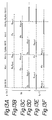
- the calculation of the second term in the right hand side of the above equation is effected, as shown in Figs 13A - 13F, as follows. That is, consider a series of the input data x(n) with a period (N+L-1), and consider a series with (N+L-1) period including L samples of error data e(n), e(n+1), ..., e(n+L-1) and (N-1) "0"s padded. Each element of the input data series x(n-N+1), , x(n+L-1) is multiplied to the series including the error data and the "0"s.
- Figure 14 is a block diagram of a conventional echo canceller using the block LMS algorihms and including the updating portion of the coefficients utilizing the above mentioned theory.
- 140 is an overlap processing part; 141 is an (N+L-1)-point FFT; 142 is a complex multiplication part; 143 is an (N+L-1) point inverse FFT; 144 is an output processing part for outputting the last L samples; 145 is a zero padding part; 146 is an (N+L-1) point FFT, 147 is a complex multiplication part; 148 is an IFFT; and 149 is an FFT.
- the overlap processing part 140 receives an input signal x(n) and makes (N+L-1) samples as one block. Then, by overlapping L samples of one block and the successive block, the overlap processing part 140 outputs (N+L-1) samples of the input data x(n).
- the (N+L-1) point FFT 141 receives each block of the input data x(n) too carry out a Fourier transform on each reveived block so that the input data x(n), which is represented in the time domain, is transformed to the signals X o (k), X 1 (k), ... X (N+L-2) (k), which are represented in the frequency domain.
- the coefficients are respectively multiplied to the signals X o (k), X 1 (k), ..., X (N+L-2) (k) in the frequency domain.
- the (N+L-1) point IFFT 143 receives the results of the multiplications and transforms the signals from the frequency domain representation to the time domain representation.
- the output processing part 144 receives the (N+L-1) samples of the time domain representation and outputs
- the output signal y(n) is subtracted from the echo signal y(n) passed through the acoustic echo path, resulting in an error signal e(n).
- the error signal e(n) has L samples.
- (N-1) "0"s are padded in the portion preceding the L samples of the error signal e(n).
- the (N+L-1) point FFT 146 receives the (N+L-1) samples of the "0"s and error signal e(n) to transform them into signals in the frequency domain.
- the signals Ek, and the complex conjugates of the signal X o (k), X i (k), X (N+L-2) k are respectively multiplied.
- the multiplied results are applied to the IFFT 148 so that the signals are transformed from the frequency domain representation to the time domain representation.
- the preceding N samples of the output of the IFFT 148 are supplied to the FFT 149, while the FFT 149 receives (L-1) samples of "0"s as the last (L-1) samples of the input signal.
- updating parts of the tap coefficients are obtained.
- the tap coefficients are once updated, or in other words, refreshed, after introducing each block of the input data x(n).
- the refreshing of the tap coefficients is further described.
- the tap coefficients are updated at each input of one block. Assuming that the L samples constitute one adaptation block, and assuming that k is an integer, then, as the coefficient values in the period between kL and ⁇ KL+(L-1) ⁇ , the values of which were updated at the time KL, are used.
- the next coefficient values at the next time (K+1)L are determined in such a way that the sum of the squares of the errors during the period between KL and ⁇ KL+(L-1) ⁇ is made minimum. In this case. assumina that the evaluation number is D. then. can be obtained.
- the error e KL+1 can be expressed as: where h i represents an impulse response of the actual system; represents an estimated impulse response; and X KL+l-1 represents a sample of the series of the input data. Whereas, the following equation stands.
- the output vector is obtained by the latter half L samples of the cyclic convolution with a periodic period equal to (N+L-1) of the vectors H T K and X T K expressed by the equations (10) and (11).
- the FFT of the output of the cyclic convolution is the products of the FFT of each element which is subject to convolution. Therefore, the fundamental structure of the echo canceller shown in Fig 14 is constructed by the parts 140 - 144.
- the coefficients H 0 K - H K (N+L-2) are updated by the outputs of the FFT 149.
- (L-1) zeros are padded in the FFT 149 to the second term in the equation (8), which is thus changed as follows.
- the length of the impulse response is so long that the number N becomes several thousand or more.
- the block length L should be as small as possible, because it-provides, as it is, a processing delay, and in order to minimize the influence due to fluctuation of the system. If L is sufficiently small in comparison with N, the value expressed by the equation (14) or (15) becomes almost equal to or larger than 2N.
- an object of the present invention is to provide a new echo canceller and a method for cancelling an echo signal in which the number of multiplications is decreased and the processing delay is shortened.
- an echo canceller for cancelling an echo signal passed through an echo path with an impulse response h(n), having an input end for receiving an input digital signal series x(n) and an output end for providing an error signal e(n).
- the echo canceller comprises:
- Figure 1 illustrates a general structure of an echo canceller according to an embodiment of the present invention.
- a tap number N which is determined by the impulse response of the system to be estimated, is considered to consist of k blocks of N'samples.
- the part 10 outputs 2N' samples (or 2 frames) in which N' samples are overlapped in the current input and the preceding input.
- a first 2N'-point FFT 11 receives the 2N' samples from the part 10 to effect a fast Fourier transform on the received 2N' samples so that the signals in the time domain are converted into the signals in the frequency domain.
- each of the 2N' points output from the first 2N'-point FFT 11 is delayed by N' x P samples, where 0 Z P Z k-1.
- the delayed 2N' samples are respectively multiplied with coefficients output from an update control part 17, and the multiplied outputs are added to obtain 2N' outputs of the FIR filter 12.
- a 2N' points IFFT effects an inverse FFT on the 2N' outputs from the FIR filter 12 so that the signals of 2N' samples in the frequency domain are converted into signals in the time domain.
- An output processing part 16 deletes the first half N' samples from the outputs of the 2N' points IFFT 15 and outputs the last N' samples.
- the update control part 17 effects an updating process of the coefficients of the FIR filter 12.
- a delay circuit 18 receives an echo component y(n) passed through the echo path 19 and delays it by N' samples.
- a subtractor 20 subtracts the output of the last N' samples of the output processing part 16 from the output of the delay circuit 8 to obtain error signals.
- the FIR filtering is executed on the shortened block of N' samples by dividing the impulse response having the length N into k blocks, the process delay is greatly shortened while the merits of the echo canceller utilizing FFT, i.e., the small number of multiplications, are maintained.
- the estimated value y(n) is considered to be a sum of the convolution of each block and the input data x(n) when the impulse response length of the system to be estimated is N, which is divided into the blocks each having N' samples.
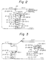
- Figure 2 shows an FIR filter having a tap number 2N'.
- 21-0 through 21-(2N'-2) are delay elements, each providing one sample of delay for the input signal x(n)
- the multiplied results are added by an adder 23.
- the added result is subtracted from the echo signal y(n) by a subtractor 20 to obtain an error signal e(n).
- An adaptive control is effected to make the error signal e(n) zero.
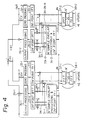
- the FIR filter having the tap number 2N' shown in Fig. 2 can be considered to be a composite filter including a block Bl with a tap number N' and a block B2 with a tap number N'. Therefore, the FIR filter shown in Fig. 2 can be expressed as shown in Fig 3.
- Figs. 2 and 3 the same reference symbols represent the same parts.
- the left side of Fig 3 includes the block B1, and the right side of Fig 3 includes the block B2.
- the outputs of the block B1 are added by an adder 23-1, and the output of the adder 23-1 is subtracted from the echo signal y(n) by a subtractor 20-1.
- the input signal x(n) is delayed by N' samples by delay elements 24-0 through 24-(N'-1) to be inputted into the block B2.
- the outputs of the block B2 are added by an adder 23-2, and the output of the adder 23-2 is subtracted from the output of the subtractor 20 to provide the error signal e(n).
- the constitution of the circuit in the right side or in the left side in Fig. 3 is substantially the same as the conventional constitution shown in Fig. 14 except for the number of samples to be processed. Accordingly, the detailed construction of the echo canceller shown in Fig. 3 can be depicted as the construction shown in Fig. 4.
- reference symbols 31-1 and 31-2 are N' overlap processing parts and 2N'-point FFTs; 32-1 and 32-2 are zero padding parts for padding N' zeros to the portion preceding the error signal e(n) at the output OUT; 33-1 and 33-2 are 2N' point FFT processing parts for effecting FFT on the outputs of the zero padding parts 32-1 and 12-2; 34-1 and 34-2 are coefficients multiplying parts or, in other words, FIR filtering parts; 35-1 and 35-2 are 2N' points inverse FFT processing parts; 36-1 and 36-2 are output processing parts for outputting the last N' samples by deleting the preceding N' samples; 37-1 and 37-2 are inverse FFT processing parts; and 18-1 and 38-2 are FFT processing parts.
- the IFFT processing parts 37-1 and 37-2 and the FFT processing parts 38-1 and 38-2 operate to provide the updated coefficients Ho and H ⁇ .
- the IFFT processing parts 37-1 and 37-2 and the FFT processing parts 38-1 and 38-2 for updating the coefficients can be omitted.
- the difference between the left side circuit and the right side circuit in Fig. 4 is that the outputs of the part 31-2 are respectively delayed by one sample by delay elements 39-0, 39-1, and 39-(2N'-1). This corresponds to the N' samples of the delay elements shown in the right side circuit in Fig. 3.
- Figure 5 shows an equivalent system to the construction shown in Fig. 4 except that the IFFT processing parts 37-1 and 37-2 and the FFT parts 38-1 and 38-2 in Fig. 4 are omitted in Fig. 5 and the separate parts 311 and 31-2, 32-1 and 32-2, 33-1 and 33-2, 34-1 and 34-2, 35-1 and 35-2, 36-1 and 36-2 in Fig. 4 are respectively combined as unit parts 31 through 36 in Fig. 5.
- the FIR filtering part 34 has two-divided portions as already shown in Fig 2.
- the 2N' outputs of the N' sample overlap processing part and the 2N' point FFT 31 and the estimated coefficients Hothrough H 2N'-1 0 are multiplied to obtain these products.
- the above-mentioned 2N' outputs are delayed by the delay elements 39-0 through 39-(2N'-1). Then, the delayed outputs are multiplied to the estimated coefficients H i o through to obtain these products.
- the products with respect to the first output are summed by the adder 40-0.
- the input signal having the impulse response of N samples is divided into two so that the processing is effected on each block with N' samples, and the process delay is shortened to be N' samples.
- the FIR filter is divided into only two for the sake of simplicity of the description.
- the present invention is not restricted to the above embodiment, and similar considerations are possible even when the number of divisions is increased.
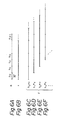
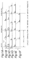
- Figures 6A through 6F are diagrams for explaining the concept of dividing the FIR filter into k blocks.
- the estimated impulse response h is divided into k blocks h o , h i , ..., h k-1 , each block consisting of N'samples.
- Figure 6B shows the input signal x.
- the output of the FIR filter is the sum of the convolutions of each block h i and the input signal x.
- the convolutions are shown in Figs. 6C, 6D, 6E, 6F, ... as the expressions h o * x, h i * x, ... and h k-1 *x.
- the convolution output is delayed by ixN' samples. Therefore, under the assumption that the updating period of the tap coefficients of the block LMS algorithm is N'samples, the output of the FFT for i-th block must be delayed by i samples.
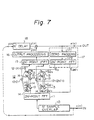
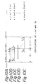
- Figure 7 is a block diagram showing an echo canceller in which an FIR filter is divided into k blocks, taking into account the consideration described with reference to Figs. 6A through 6F, according to another embodiment of the present invention.
- Fig. 7 the construction is similar to the conventional one shown in Fig. 13 except that, in Fig. 7, the number of samples in one block is N' and the FIR filter includes k delay elements 13 connected in series for each block.
- the multiplied results are summed by adders 12-0 through 12-(2N'-1).
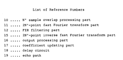
- Reference number 10 represents an N' sample overlap processing part; 11 is a 2N' point FFT processing part; 15 is a 2N' point IFFT processing part; 16 is an output processing part for deleting the preceding N' samples and outputting the latter half N' samples; 17 is a coefficient updating part; 171 is a zero padding part for padding N' zeros into the preceding half N' samples of the error signal e(n); and 172 is a 2N' point FFT processing part for processing the output of the zero padding part.
- the constitution of the coefficient updating part 17 is simple because the IFFT 37-1 or 37-2 and the FFT 38-1 or 18-2 are omitted.
- the input signal x(n) from the input terminal IN is processed by the N' sample overlap processing part 10 so that a unit consisting of 2N' samples of the input signals is output at each output timing.
- the latter half N' samples of the current unit of 2N' samples are overlapped with the preceding half N' samples of the immediately before output (see Figs. 6B through 6F).
- the 2N' samples output from the N' sample overlap processing part 10 are received by the 2N' point FFT processing part 11 and are processed by a fast Fourier transform so that the input signal expressed in the time domain is transformed into the signal expressed in the frequency domain.
- the complex conjugates of the 2N' outputs from the 2N'-point FFT processing part 11 are respectively multiplied with the error coefficients E o through E 2N' - l which are output from the 2N'-point FFT processing part 172 in the coefficient updating part 17 at the error signal side, resulting in the updating parts of the coefficients Ho through H 0 2N'-1 , which correspond to the block h o .
- the complex conjugates thereof are multiplied with the error coefficients E o through E 2N'-1 so that the updating parts of the coefficients Ho through corresponding to the block h 1 are obtained.
- the coefficients obtained in such a way as above are classified into groups respectively corresponding to the outputs of the 2N' point FFT processing part 11.
- the multiplied data by the classified coefficients Ho through through ... and through are summed respectively by the adders 12-0 through 12-(2N'-1).
- the added results are input to the 2N' point IFFT processing part 15 and are processed therein by an inverse fast Fourier transform.
- the preceding half N' samples are deleted so that the last half N' samples are output as the estimated echo signal y(n).
- the error signal e(n) is obtained.
- the delay in the N' delay circuit 18 can be made as short as N'.
- the delay N' can be made smaller and smaller by increasing the number of divided blocks so that the processing delay can be reduced.
- the coefficient updating part 17 is simplified.
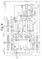
- Figure 8 shows an another embodiment of the present invention in which only a coefficient updating part 17a is different from the coefficient updating part 17 shown in Fig 7.
- the other parts are similar to those shown in Fig 7.
- the coefficient updating part 17a includes the zero padding part 171, the 2N'-point FFT processing part 172, multipliers 173, 174, ..., 2N'-point IFFT processing parts 175-0 through 175-(k-1), and 2N'-point FFT processing parts 176-0 through 176-(k-1).
- a block adaptive algorithm can be realized with a smaller number of multiplications than conventionally used.
Landscapes
- Engineering & Computer Science (AREA)
- Computer Networks & Wireless Communication (AREA)
- Signal Processing (AREA)
- Cable Transmission Systems, Equalization Of Radio And Reduction Of Echo (AREA)
- Filters That Use Time-Delay Elements (AREA)
Abstract
Claims (7)
caractérisé en ce que
Applications Claiming Priority (4)
| Application Number | Priority Date | Filing Date | Title |
|---|---|---|---|
| JP256750/86 | 1986-10-30 | ||
| JP25675086 | 1986-10-30 | ||
| JP265470/86 | 1986-11-10 | ||
| JP26547086 | 1986-11-10 |
Publications (2)
| Publication Number | Publication Date |
|---|---|
| EP0288577A1 EP0288577A1 (fr) | 1988-11-02 |
| EP0288577B1 true EP0288577B1 (fr) | 1992-06-03 |
Family
ID=26542881
Family Applications (1)
| Application Number | Title | Priority Date | Filing Date |
|---|---|---|---|
| EP87907135A Expired - Lifetime EP0288577B1 (fr) | 1986-10-30 | 1987-10-29 | Suppresseur d'echo a court delai de traitement et nombre reduit de multiplications et procede de suppression de signal d'echo |
Country Status (4)
| Country | Link |
|---|---|
| US (1) | US4951269A (fr) |
| EP (1) | EP0288577B1 (fr) |
| CA (1) | CA1332187C (fr) |
| WO (1) | WO1988003341A1 (fr) |
Families Citing this family (26)
| Publication number | Priority date | Publication date | Assignee | Title |
|---|---|---|---|---|
| NL9001016A (nl) * | 1990-04-27 | 1991-11-18 | Philips Nv | Digitale echocompensator met een dubbelspraakdetector. |
| US5117418A (en) * | 1990-11-09 | 1992-05-26 | Intelligent Modem Corporation | Frequency domain adaptive echo canceller for full-duplex data transmission |
| SE467680B (sv) * | 1990-12-19 | 1992-08-24 | Johan Hellgren | Digital filterbank med minskad effektfoerbrukning |
| CA2060667C (fr) * | 1992-02-05 | 1998-12-08 | Paul Marc Yatrou | Contact pour connecteur electrique protege par un feuil de polymere, et methode de production |
| WO1994001933A1 (fr) * | 1992-07-07 | 1994-01-20 | Lake Dsp Pty. Limited | Filtre numerique a haute precision et a haut rendement |
| FR2702612B1 (fr) * | 1993-03-10 | 1995-06-09 | France Telecom | Procede et dispositif de filtrage d'un signal temporel numerique, et application a la correction d'echos dans un canal de transmission . |
| US5329587A (en) * | 1993-03-12 | 1994-07-12 | At&T Bell Laboratories | Low-delay subband adaptive filter |
| DE4317043B4 (de) * | 1993-05-21 | 2004-03-25 | Deutsche Telekom Ag | Verfahren und Vorrichtung zur Echokompensation in Übertragungssystemen |
| JPH06338829A (ja) * | 1993-05-28 | 1994-12-06 | American Teleph & Telegr Co <Att> | 通信システム内の反響除去方法と装置 |
| JPH0784993A (ja) * | 1993-09-17 | 1995-03-31 | Fujitsu Ltd | 信号抑圧装置 |
| AT403217B (de) * | 1994-02-11 | 1997-12-29 | Siemens Ag Oesterreich | Digitalfilter für spektralanalysen |
| EP0693747A3 (fr) * | 1994-07-18 | 1997-12-29 | Gec-Marconi Limited | Dispositif pour supprimer des vibrations |
| GB9414484D0 (en) * | 1994-07-18 | 1994-09-21 | Marconi Gec Ltd | An apparatus for cancelling vibrations |
| US5526426A (en) * | 1994-11-08 | 1996-06-11 | Signalworks | System and method for an efficiently constrained frequency-domain adaptive filter |
| US6125179A (en) * | 1995-12-13 | 2000-09-26 | 3Com Corporation | Echo control device with quick response to sudden echo-path change |
| US6002722A (en) * | 1996-05-09 | 1999-12-14 | Texas Instruments Incorporated | Multimode digital modem |
| FR2764469B1 (fr) * | 1997-06-09 | 2002-07-12 | France Telecom | Procede et dispositif de traitement optimise d'un signal perturbateur lors d'une prise de son |
| SG71035A1 (en) * | 1997-08-01 | 2000-03-21 | Bitwave Pte Ltd | Acoustic echo canceller |
| SG77611A1 (en) | 1997-11-13 | 2001-01-16 | Univ Singapore | Acoustic echo cancellation equipped with howling suppressor and double-talk detector |
| EP1110155A1 (fr) | 1998-09-03 | 2001-06-27 | Conexant Systems, Inc. | Procede de filtrage dans le domaine frequentiel utilisant une transformee reelle a analytique |
| US6654429B1 (en) * | 1998-12-31 | 2003-11-25 | At&T Corp. | Pilot-aided channel estimation for OFDM in wireless systems |
| US6269161B1 (en) | 1999-05-20 | 2001-07-31 | Signalworks, Inc. | System and method for near-end talker detection by spectrum analysis |
| US6898185B1 (en) * | 1999-10-20 | 2005-05-24 | Broadcom Corporation | Diagnostics of cable and link performance for a high-speed communication system |
| DE10043064B4 (de) * | 2000-09-01 | 2004-07-08 | Dietmar Dr. Ruwisch | Verfahren und Vorrichtung zur Elimination von Lautsprecherinterferenzen aus Mikrofonsignalen |
| CN100518043C (zh) * | 2003-07-08 | 2009-07-22 | 聚信科技有限公司 | 一种频域滤波器及实现频域滤波的方法 |
| US7480377B2 (en) * | 2003-12-31 | 2009-01-20 | Intel Corporation | Dual adaptive filter apparatus and method |
Family Cites Families (3)
| Publication number | Priority date | Publication date | Assignee | Title |
|---|---|---|---|---|
| US4355368A (en) * | 1980-10-06 | 1982-10-19 | The United States Of America As Represented By The Secretary Of The Navy | Adaptive correlator |
| DE3376943D1 (en) * | 1983-06-30 | 1988-07-07 | Ibm | Starting-up method for an echo canceller filter, and communication system using this method |
| NL8601604A (nl) * | 1986-06-20 | 1988-01-18 | Philips Nv | Frequentie-domein blok-adaptief digitaal filter. |
-
1987
- 1987-10-29 EP EP87907135A patent/EP0288577B1/fr not_active Expired - Lifetime
- 1987-10-29 CA CA000550527A patent/CA1332187C/fr not_active Expired - Fee Related
- 1987-10-29 WO PCT/JP1987/000833 patent/WO1988003341A1/fr not_active Ceased
- 1987-10-29 US US07/216,907 patent/US4951269A/en not_active Expired - Fee Related
Non-Patent Citations (2)
| Title |
|---|
| IEEE Communications Magazine, vol. 20, no. 3, May 1982, IEEE, (New York, US); F.J. Harris: "The discrete Fourier transform applied to time domain signal processing", pages 13-22 * |
| IEEE Transactions on Acoustics, Speech, and Signal Processing, vol. ASSP-30, no. 5, October 1982, IEEE, (New York,US); D. Mansour et al.: "Unconstrained frequency-domain adaptive filter", pages 726-734 * |
Also Published As
| Publication number | Publication date |
|---|---|
| EP0288577A1 (fr) | 1988-11-02 |
| WO1988003341A1 (fr) | 1988-05-05 |
| CA1332187C (fr) | 1994-09-27 |
| US4951269A (en) | 1990-08-21 |
Similar Documents
| Publication | Publication Date | Title |
|---|---|---|
| EP0288577B1 (fr) | Suppresseur d'echo a court delai de traitement et nombre reduit de multiplications et procede de suppression de signal d'echo | |
| JP3177562B2 (ja) | 少遅延サブバンド適応フィルタ装置 | |
| CA2122107C (fr) | Eliminateur de bruit actif a injection de retards multiples non entiers de la periode d'echantillonnage | |
| US5590121A (en) | Method and apparatus for adaptive filtering | |
| US5568558A (en) | Adaptive noise cancellation device | |
| US4038536A (en) | Adaptive recursive least mean square error filter | |
| EP0649578B1 (fr) | Filtre numerique a haute precision et a haut rendement | |
| US5208786A (en) | Multi-channel signal separation | |
| US6738480B1 (en) | Method and device for cancelling stereophonic echo with frequency domain filtering | |
| EP0281101B1 (fr) | Circuit d'annulation d'une forme d'onde en entier ou en partie utilisant des filtres non récursifs et récursifs | |
| US6108413A (en) | Echo cancellation method and echo canceller implementing such a process | |
| US5428562A (en) | Fast converging adaptive filter | |
| US5568411A (en) | Method and apparatus for using polarity-coincidence correlators in LMS adaptive filters | |
| JP2924762B2 (ja) | アダプティブフィルタ及びその適応化方法 | |
| US6999509B2 (en) | Method and apparatus for generating a set of filter coefficients for a time updated adaptive filter | |
| US7103623B2 (en) | Partitioned block frequency domain adaptive filter | |
| JP2002522969A (ja) | 計算を簡単にした周波数濾波用デジタル処理装置 | |
| JPH09261135A (ja) | 音響エコー消去装置 | |
| JP4132578B2 (ja) | 回り込みキャンセラ | |
| JPS63503031A (ja) | 処理遅延が短かく且つ乗算数が少ないエコーキャンセラ | |
| EP0651899B1 (fr) | Module de filtre d'annulation adaptatif | |
| Chen et al. | A zero-delay FFT-based subband acoustic echo canceller for teleconferencing and hands-free telephone systems | |
| DE3779624T2 (de) | Echokompensator mit kurzer verarbeitungsverzoegerung und reduzierter multiplikationszahl und verfahren zur echokompensation. | |
| JPH0447720A (ja) | エコーキャンセラー | |
| JPH0563609A (ja) | エコーキヤンセラ方式 |
Legal Events
| Date | Code | Title | Description |
|---|---|---|---|
| PUAI | Public reference made under article 153(3) epc to a published international application that has entered the european phase |
Free format text: ORIGINAL CODE: 0009012 |
|
| 17P | Request for examination filed |
Effective date: 19880629 |
|
| AK | Designated contracting states |
Kind code of ref document: A1 Designated state(s): DE FR GB SE |
|
| 17Q | First examination report despatched |
Effective date: 19910424 |
|
| GRAA | (expected) grant |
Free format text: ORIGINAL CODE: 0009210 |
|
| AK | Designated contracting states |
Kind code of ref document: B1 Designated state(s): DE FR GB SE |
|
| REF | Corresponds to: |
Ref document number: 3779624 Country of ref document: DE Date of ref document: 19920709 |
|
| PGFP | Annual fee paid to national office [announced via postgrant information from national office to epo] |
Ref country code: FR Payment date: 19920723 Year of fee payment: 6 |
|
| ET | Fr: translation filed | ||
| PGFP | Annual fee paid to national office [announced via postgrant information from national office to epo] |
Ref country code: GB Payment date: 19921016 Year of fee payment: 6 |
|
| PGFP | Annual fee paid to national office [announced via postgrant information from national office to epo] |
Ref country code: SE Payment date: 19921026 Year of fee payment: 6 |
|
| PGFP | Annual fee paid to national office [announced via postgrant information from national office to epo] |
Ref country code: DE Payment date: 19921130 Year of fee payment: 6 |
|
| PLBE | No opposition filed within time limit |
Free format text: ORIGINAL CODE: 0009261 |
|
| STAA | Information on the status of an ep patent application or granted ep patent |
Free format text: STATUS: NO OPPOSITION FILED WITHIN TIME LIMIT |
|
| 26N | No opposition filed | ||
| PG25 | Lapsed in a contracting state [announced via postgrant information from national office to epo] |
Ref country code: GB Effective date: 19931029 |
|
| PG25 | Lapsed in a contracting state [announced via postgrant information from national office to epo] |
Ref country code: SE Effective date: 19931030 |
|
| GBPC | Gb: european patent ceased through non-payment of renewal fee |
Effective date: 19931029 |
|
| PG25 | Lapsed in a contracting state [announced via postgrant information from national office to epo] |
Ref country code: FR Effective date: 19940630 |
|
| PG25 | Lapsed in a contracting state [announced via postgrant information from national office to epo] |
Ref country code: DE Effective date: 19940701 |
|
| REG | Reference to a national code |
Ref country code: FR Ref legal event code: ST |
|
| EUG | Se: european patent has lapsed |
Ref document number: 87907135.5 Effective date: 19940510 |