EP0289040B1 - Kombinierte Laser-Stanzpresse - Google Patents
Kombinierte Laser-Stanzpresse Download PDFInfo
- Publication number
- EP0289040B1 EP0289040B1 EP88106904A EP88106904A EP0289040B1 EP 0289040 B1 EP0289040 B1 EP 0289040B1 EP 88106904 A EP88106904 A EP 88106904A EP 88106904 A EP88106904 A EP 88106904A EP 0289040 B1 EP0289040 B1 EP 0289040B1
- Authority
- EP
- European Patent Office
- Prior art keywords
- laser
- processing machine
- generator
- composite processing
- punch
- Prior art date
- Legal status (The legal status is an assumption and is not a legal conclusion. Google has not performed a legal analysis and makes no representation as to the accuracy of the status listed.)
- Expired - Lifetime
Links
Images

Classifications
-
- F—MECHANICAL ENGINEERING; LIGHTING; HEATING; WEAPONS; BLASTING
- F16—ENGINEERING ELEMENTS AND UNITS; GENERAL MEASURES FOR PRODUCING AND MAINTAINING EFFECTIVE FUNCTIONING OF MACHINES OR INSTALLATIONS; THERMAL INSULATION IN GENERAL
- F16F—SPRINGS; SHOCK-ABSORBERS; MEANS FOR DAMPING VIBRATION
- F16F15/00—Suppression of vibrations in systems; Means or arrangements for avoiding or reducing out-of-balance forces, e.g. due to motion
- F16F15/02—Suppression of vibrations of non-rotating, e.g. reciprocating systems; Suppression of vibrations of rotating systems by use of members not moving with the rotating systems
- F16F15/023—Suppression of vibrations of non-rotating, e.g. reciprocating systems; Suppression of vibrations of rotating systems by use of members not moving with the rotating systems using fluid means
- F16F15/0232—Suppression of vibrations of non-rotating, e.g. reciprocating systems; Suppression of vibrations of rotating systems by use of members not moving with the rotating systems using fluid means with at least one gas spring
-
- B—PERFORMING OPERATIONS; TRANSPORTING
- B21—MECHANICAL METAL-WORKING WITHOUT ESSENTIALLY REMOVING MATERIAL; PUNCHING METAL
- B21D—WORKING OR PROCESSING OF SHEET METAL OR METAL TUBES, RODS OR PROFILES WITHOUT ESSENTIALLY REMOVING MATERIAL; PUNCHING METAL
- B21D43/00—Feeding, positioning or storing devices combined with, or arranged in, or specially adapted for use in connection with, apparatus for working or processing sheet metal, metal tubes or metal profiles; Associations therewith of cutting devices
- B21D43/28—Associations of cutting devices therewith
- B21D43/282—Discharging crop ends or the like
-
- B—PERFORMING OPERATIONS; TRANSPORTING
- B23—MACHINE TOOLS; METAL-WORKING NOT OTHERWISE PROVIDED FOR
- B23K—SOLDERING OR UNSOLDERING; WELDING; CLADDING OR PLATING BY SOLDERING OR WELDING; CUTTING BY APPLYING HEAT LOCALLY, e.g. FLAME CUTTING; WORKING BY LASER BEAM
- B23K26/00—Working by laser beam, e.g. welding, cutting or boring
- B23K26/0093—Working by laser beam, e.g. welding, cutting or boring combined with mechanical machining or metal-working covered by other subclasses than B23K
-
- B—PERFORMING OPERATIONS; TRANSPORTING
- B23—MACHINE TOOLS; METAL-WORKING NOT OTHERWISE PROVIDED FOR
- B23K—SOLDERING OR UNSOLDERING; WELDING; CLADDING OR PLATING BY SOLDERING OR WELDING; CUTTING BY APPLYING HEAT LOCALLY, e.g. FLAME CUTTING; WORKING BY LASER BEAM
- B23K26/00—Working by laser beam, e.g. welding, cutting or boring
- B23K26/70—Auxiliary operations or equipment
- B23K26/702—Auxiliary equipment
-
- B—PERFORMING OPERATIONS; TRANSPORTING
- B23—MACHINE TOOLS; METAL-WORKING NOT OTHERWISE PROVIDED FOR
- B23P—METAL-WORKING NOT OTHERWISE PROVIDED FOR; COMBINED OPERATIONS; UNIVERSAL MACHINE TOOLS
- B23P23/00—Machines or arrangements of machines for performing specified combinations of different metal-working operations not covered by a single other subclass
- B23P23/04—Machines or arrangements of machines for performing specified combinations of different metal-working operations not covered by a single other subclass for both machining and other metal-working operations
-
- B—PERFORMING OPERATIONS; TRANSPORTING
- B26—HAND CUTTING TOOLS; CUTTING; SEVERING
- B26D—CUTTING; DETAILS COMMON TO MACHINES FOR PERFORATING, PUNCHING, CUTTING-OUT, STAMPING-OUT OR SEVERING
- B26D7/00—Details of apparatus for cutting, cutting-out, stamping-out, punching, perforating, or severing by means other than cutting
- B26D7/18—Means for removing cut-out material or waste
-
- B—PERFORMING OPERATIONS; TRANSPORTING
- B26—HAND CUTTING TOOLS; CUTTING; SEVERING
- B26F—PERFORATING; PUNCHING; CUTTING-OUT; STAMPING-OUT; SEVERING BY MEANS OTHER THAN CUTTING
- B26F1/00—Perforating; Punching; Cutting-out; Stamping-out; Apparatus therefor
- B26F1/02—Perforating by punching, e.g. with relatively-reciprocating punch and bed
Definitions
- the present invention relates to a laser-punch composite processing machine which performs a punching process and a laser process on a plate workpiece, and more specifically to a composite processing machine which can be moved and installed with ease.
- this laser-punch composite processing machine comprises a punch tool which moves freely in the vertical direction, a laser processing head for emitting a laser beam, and a workpiece moving and positioning device for moving and positioning the workpiece at a location below the punching tool or laser head.
- US-A-4 335 296 which forms the basis for the pre-characterising part of Claim 1 discloses a machine tool having a laser beam cutting device, wherein the cutting head of the device and the tube connecting the cutting head with the laser generator are mounted on an overhead beam connected to a sleeve. The sleeve is turnable about the axis of a column which is independent and disassociated from the machine tool.
- the apparatus of US-A-4 335 296 comprises a common base on which a punching installation, a laser processing head and a laser beam generator are disposed.
- the laser processing head section is supported on a frame through a vibration-proofing device.
- an optical path tube for guiding the laser beam from the laser generator to the laser processing head section is supported by simple means onto the punch press frame. Accordingly, problems arise when vibrations are transmitted to the laser processing head via the optical path tube.
- a first object of the present invention is to provide, with due consideration to the drawbacks of such conventional devices, a laser-punch composite processing machine wherein transmission of vibrations from the punch press to the laser generator is effectively suppressed, transportation and the like is easily performed, and adjustment of the optical axis setting is carried out with ease.
- This objective is accomplished in the present invention by installing a vibration-proofing frame on a side of the frame of the punch press by means of a connecting member, and by mounting a position and supporting device, formed of a unitized air springs, and a position control device on top of this antivibration frame.
- the laser generator is supported on top of these devices.
- a laser beam path tube is provided between a generator side tube provided on the laser generator side and a bending mirror section tube provided on the laser processing head side, one end of the bending mirror section tube is set in a loose-fitting manner on one end of the laser beam path tube and gas is caused to flow out from a loose opening between the laser beam path tube and the bending mirror section tube.
- a freely inclinable chute is provided in a certain direction on the worktable for supporting the workpiece, such that the finished workpiece is removed by the inclination of the chute.
- a laser-punch composite processing machine comprising a main frame and a laser beam generator characterised in that the processing machine further comprises a pre-loaded vibration-proofing frame, the vibration-proofing frame being mounted on the main frame and the laser beam generator being mounted on the vibration-proofing frame.
- a laser-punch composite processing machine comprising: a main frame, a worktable mounted on the main frame for supporting a workpiece; a punch tool and a die tool mounted on the main frame for punching a workpiece positioned therebetween, in corporation with each other; a vertically reciprocatable punch ram mounted on the main frame for striking the punch tool and causing the punch tool to perform the punching operation; a laser processing head mounted on the main frame for emitting a laser beam to perform a laser processing on a workpiece; a laser beam generator and an optical beam pathway for guiding the laser beam output from the laser beam generator to the laser processing head, characterised in that the processing machine further comprises a vibration-proofing frame mounted on the main frame with a preload to enhance the vibration-proofing property thereof, wherein the laser beam generator is mounted on the vibration-proofing frame through vibration-proofing means.
- a laser-punch composite processing machine comprising: a main frame comprising a pedestal portion having a lower height compared with other portions thereof; a worktable mounted on the main frame for supporting a workpiece; a punch tool and a die tool mounted on the main frame for punching a workpiece positioned therebetween, in corporation with each other; a vertically reciprocatable punch ram mounted on the main frame for striking the punch tool and causing the punch tool to perform a punching operation; a laser processing head mounted on the main frame for emitting a laser beam to perform a laser processing on a workpiece; and an optical beam pathway for guiding the laser beam output from the laser generator to the laser processing head, characterised in that the processing machine further comprises a vibration-proofing frame having substantially the same height as that of the other portions of the main frame and mounted on the pedestal portion of the main frame, wherein the laser beam generator is mounted on the vibration-proofing frame through vibration-proofing means.
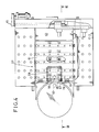
- a laser generator 5 and a laser processing head 7 are mounted on a punch press 3.
- the punch press 3 is constructed in an integral configuration with a gate-shaped frame 11 on a common base 9.
- a vertical reciprocatable punch ram for striding a punch tool upper and lower turrets 13 equipped with a large number of punches and dies supported rotatably by a motor (not shown), and a workpiece moving and positioning device 15 are provided for moving and positioning a plate workpiece horizontally in the X-and Y-axis directions.
- the laser generator 5 is mounted on the common base 9 close to the punch press 3.
- a vibration-proofing frame 17 is integrally mounted on the common base 9 through a plurality of fastening members 19.
- a vibration-proofing base 21 is supported on the vibration-proofing frame 17 through a plurality of positioning support devices 23.
- the laser generator 5 is mounted on the vibration-proofing base 21.
- the vibration-proofing frame 17 is provided with a leg section 17L at each of its four corners, and is formed in a box shape with a plurality of horizontal beam sections 17B which mutually link the upper and lower portions of each of the leg sections 17L.
- the fastening members 19 are formed of tie rods which pass through each of the leg sections 17L of the vibration-proofing frame 17. The lower end of each tie rod is screwed into the common base 9. Because they are securely fastened, the fastening members 19 can maintain a state of high stress in the leg sections 17L of the vibration-proofing frame 17, thereby increasing the damping capability of the vibration-proofing frame 17.
- the positioning support device 23 supports the vibration-proofing base 21, eliminating vibrations from the punch press 3, and correctly positions the laser generator 5 relative to the common base 9.
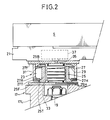
- the construction of the positioning support device 23 is shown in Fig. 2.
- a cylindrical first tube member 25 is integrally erected on the upper surface of the legs 17L of the vibration-proofing frame 17 by means of a bolt or the like.
- the first tube member 25 in this embodiment of the present invention engages internally with a cylindrical second tube member 27 mounted on the bottom surface of the vibration-proofing base 21.
- a flange section 27F is integrally provided at the upper section of the section tube member 27 in order for mounting the positioning support device 23 to the vibration-proofing base 21.
- a ring plate 27R provided with a tapered orifice section 27T for engaging the first tapered section 25T in a freely disengaging manner, is integrally mounted on the lower section of the second tube member 27.
- a packing member 29, formed of rubber or the like and providing a damping effect by frictional contact with the inner circumferential surface of the second tube member 27, is mounted on the upper section of the first tube member 25 through a back-up member 25B.
- a fluid pressure chamber 31 is formed, enclosed by the first and second tube members 25 and 27 and the packing member 29.
- a fluid inlet/outlet port 27H is formed at a suitable location in the second tube member 27.
- a common air spring 33 is interposed as a fluid pressure buffer member between the flange section 25F of the first tube member 25 and the flange section 27F of the second tube member 27.
- An air inlet/outlet port 25H which communicates with the air spring 33 is provided in a suitable location in the flange section 25F of the first tube section 25.
- the air spring 33 communicates with a surge tank 37, provided in the vibration-proofing base 21, through a small-diameter orifice 35 formed in the flange section 27F of the second tube section 27.
- the vibration proofing device described above may be also used for mounting the laser processing head 7 and the bending mirror assembly 39 on the frame 11.
- the air in the air spring 33 is discharged. Then the vibration-proofing base 21 drops due to its own weight.
- the tapered section 25T of the first tube member 25 and the tapered orifice section 27T of the second tube member 27 engage, so that the laser generator 5 is positioned relative to the common base 9.
- the closed fluid pressure chamber 31 is formed by the conformation of the two tapered sections 25T and 27T. Accordingly, when the operating fluid is fed into the fluid pressure chamber 31, the second tube member 27 is pressed downward and the tapered section 25T and the tapered orifice section 27T are mutually engaged more firmly, so that precise positioning of the laser generator 5 is obtained and a stably secured state results.
- the first tubular member 25 has a configuration by which the air spring 33 is contained between the flange section 25F of the first tube member 25 and the flange section 27F of the second tube member 27, so that a unitized construction is obtained for the air spring and the position control device, allowing for easy assembly adjustment and mounting.
- the laser process head 7 for performing the processing of the workpiece by focusing a laser beam LB from the laser generator 5, is supported on the frame 11 of the punch press 3 through a suitable vibration proofing device in a manner such that its position is freely adjustable in the vertical direction.
- a mirror assembly 39 with a built-in bending mirror 41 is positioned so that its vertical position is freely adjustable by the same manner as the positioning support device 23.
- a bending mirror section tube 43 is provided, extending toward the laser generator 5 side.
- the tube 43 is aligned with a generator side tube 45 provided on the laser generator 5. Accordingly, a laser beam LB generated by the laser generator 5 is emitted onto the mirror assembly 39 and is bent at right angles by the bending mirror 41 and introduced into the laser processing head 7.
- a laser beam path tube 47 is positioned between the laser generator 5 and the mirror assembly 39 to guide the laser beam LB.
- the laser beam path tube 47 is removably supported on the frame 11 of the punch press 3 through a fixing device 49.
- the diameter of the laser beam path tube 47 is sufficiently large in comparison with the bending mirror section tube 43 and the generator size tube 45 that the end of the bending mirror section tube 43 is loosely inserted into one end of the laser beam path tube 47, so that the bending mirror section tube 43 is capable of vertical movement.
- a gas feed section 51 which supplies a compressed gas such as air and the like is provided at a suitable position on the laser beam path tube 47.
- the gas feed section 51 is connected to a suitable gas supply source such as a compressor (not shown in the figures).
- the laser beam path tube 47 does not contact the laser generator 5 or the mirror assembly 39. Accordingly, even when the punching process is carried out by the punch press 3, no vibrations is transmitted from the laser beam path tube 47 to the laser generator 5 or the mirror assembly 39. Therefore, by adequately preventing vibrations from reaching the laser generator 5, the mirror assembly 39, and the laser processing head 7, the transmission of vibrations to the apparatus from other parts of the machine can blso be eliminated, and the precision of the optical system is therefore well maintained.
- the compressed gas from the gas feed section 51 is fed into the laser beam path tube 47, the compressed gas is subsequently discharged to the outside through the loose opening between the tubes 43, 45 and the laser beam path tube 47. Therefore dust and the like are prevented from entering the inside of the optical system of the present invention through the loose opening between the tubes 43, 45 and the laser beam path tube 47. Also, the gas which is fed into the laser beam path tube 47 reaches the inside of the mirror assembly 39 and flows out through exhaust sections and minute openings formed when the mirror assembly 39 and the laser processing head 7 are assembled. Accordingly, the bending mirror 41 is effectively cooled while dust and the like are prevented from entering the mirror assembly 39 and the laser processing head 7.
- the workpiece moving and positioning device 15 is provided for moving and positioning the workpiece to a punching position 53 or a laser processing position 55.
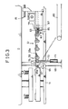
- a worktable 57 which comprises a small workchute 59 provided close to a position under the laser processing position 55, a large workchute 61 which encloses three sides of the small work chute 59, and an immobile table 63 provided next to the large work chute 61.
- the small work chute 59 is mounted in a freely swinging manner around a hinge pin 67 on a mounting member 65 provided on the frame 11.
- a vertical slot 65a is formed on the mounting member 65, and the small work chute 59 is mounted on the hinge pin 67 provided in the slot 65a.
- the slot 65a is so formed that when the hinge pin 67 is positioned at the highest point of the slot 65a and the small work chute 59 has a horizontal attitude, the top surfaces of the small work chute 59 and the large work chute 61 are aligned.
- a first hydraulic cylinder 71 is provided on a vertically telescopic dust duct 69 for collecting dust produced by laser processing, to cause the small work chute 59 to swing downward.
- the top end of a piston rod 73 which moves upward from the cylinder 71 freely supports the central section of the small work chute 59 through a roller 75.
- the first hydraulic cylinder 71 is activated and the piston rod 73 descends. Then the large work chute 61 is maintained without change in the horizontal position, and only the small work chute 59, after having descended in the range of the slot 63a while maintaining a horizontal state, inclines toward the lower right in Fig. 3, and the small product is transported to the outside of the processing machine.
- a hook plate 59a is provided at the right end of the small work chute 59 for engaging the small work chute 59 in the large workchute 61 when the large work chute 61 is activated.
- the large work chute 61 is mounted in a freely swinging manner around a hinge pin 79 on a mounting member 77 provided on the frame 11.
- a shot hole 83 for mating with a shot pin 81 provided on the immobile table 63 is formed on the right end of the large work chute 61. More specifically, the shot pin 81 is provided on the immobile table 63 through a spring 85 and a second hydraulic cylinder 87. When the second hydraulic cylinder 87 is in an unactivated state, the shot pin 81 is biased by the spring 85 to the left side of Fig. 3. When the second hydraulic cylinder 87 is activated, the shot pin 81 is biased by fluid pressure to the right side in the drawings.
- the large work chute 61 is maintained in a horizontal state. Then when the comparatively large size workpiece is being removed, the second hydraulic cylinder 87 is activated, and by the release of the mating of the shot pin 81 and the shot hole 83, the large work chute 61 can swing downward. Also, at this time, the small work chute 59 swings downward together with the large work chute 61 because the hook plate 59a is set.
- the first hydraulic cylinder 71 is activated, returning the large work chute 61 to its original state.
- the large work chute 61 turns in the counterclockwise direction in Fig. 3 as the result of the reversion of the first hydraulic cylinder 71 through the small work chute 59 and the hook plate 59a, and when the large work chute 61 reaches the horizontal position, the shot hole 87 is reengaged by the shot pin 85.
- this embodiment of the present invention has a simple configuration in which only a single small work chute, or both of the large and small work chutes, can be inclined by making use of a single hydraulic cylinder.
- a laser punch composite machine further comprises a main frame, a laser generator, a laser beam bender, and an optional beam pathway, the optical beam pathway comprising a first tube, mounted on the laser beam generator, a second tube, mounted on the laser beam bender, a third tube, mounted on the main frame, the third tube connecting the first and second tubes without physical contact therewith.
- a laser punch composite machine further comprises a work table, the work table comprising a slantable small work chute and a slantable large work chute, the small work chute being slantable both with and independently of the large work chute.
Landscapes
- Engineering & Computer Science (AREA)
- Mechanical Engineering (AREA)
- Physics & Mathematics (AREA)
- Optics & Photonics (AREA)
- Life Sciences & Earth Sciences (AREA)
- Plasma & Fusion (AREA)
- General Engineering & Computer Science (AREA)
- Forests & Forestry (AREA)
- Aviation & Aerospace Engineering (AREA)
- Acoustics & Sound (AREA)
- Agronomy & Crop Science (AREA)
- Laser Beam Processing (AREA)
- Presses And Accessory Devices Thereof (AREA)
Claims (9)
- Zusammengesetzte Laser- und Stanzbearbeitungsmaschine (1) mit einem gemeinsamen Grundrahmen (9), auf dem eine Stanzvorrichtung, ein Laserbearbeitungskopf (7) und ein Laserstrahlerzeuger (5) angeordnet sind, dadurch gekennzeichnet, daß der Laserstrahlerzeuger (5) auf dem gemeinsamen Grundrahmen (9) von teleskopischen Positioniereinrichtungen (23) abgestützt ist, die auf einen vorgespannten Rahmen (17) montiert sind, wobei die teleskopischen Positioniereinrichtungen (23) eine pneumatisch arbeitende Luftfeder (33), ein oberes Rohrelement (27) und ein unteres Rohrelement (25) beinhalten, so daß im Betrieb die Luftfeder (33) das obere Rohrelement (27) unabhängig vom unteren Rohrelement (25) dazu veranlaßt, den Laserstrahlerzeuger (5) in eine angehobene Position zu heben, um den Laserstrahlerzeuger (5) gegen Vibrationen zu isolieren, die durch den gemeinsamen Grundrahmen (9) übertragen werden.
- Laser- und Stanzbearbeitungsmaschine (1) nach Anspruch 1, in der die oberen und unteren Rohrelemente (27, 25) mit konischen Oberflächen (27T, 25T) versehen sind, so daß sie zentrierend ineinandergreifen.
- Laser- und stanzbearbeitungsmaschine (1) nach Anspruch 2, in der die oberen und unteren Rohrelemente (27, 25) zusätzlich mit hydraulischen Einrichtungen ausgestattet sind, um das zentrische Ineinandergreifen der konischen Oberflächen (27T, 25T) sicherzustellen, damit der Lasergenerator (5) in der abgesenkten Stellung mit dem Strahlenweg ausgerichtet ist, auf dem der Laserstrahl zu dem Laserbearbeitungskopf (7) zu übertragen ist.
- Laser- und Stanzbearbeitungsmaschine (1) nach Anspruch 1, 2 oder 3, in der das untere Rohrelement (25) einen Kolben (25B) und eine elastische Kolbenpackung (29) enthält, so daß gemeinsam mit dem oberen Rohrelement (27) eine Flüssigkeitskammer gebildet wird, wenn der Lasererzeuger (5) sich in der abgesenkten Position befindet, so daß die Flüssigkeitskammer die Vibrationen während des Stanzvorganges absorbiert.
- Laser- und Stanzbearbeitungsmaschine (1) nach einem der vorhergehenden Ansprüche, die einen Schwallbehälter (37) für die Schwalluft aus den Luftfedern (33) enthält.
- Laser- und Stanzbearbeitungsmaschine (1) nach einem der Ansprüche 1 bis 5, wobei der vorgespannte Rahmen (17) mittels Zugstangen (19) auf dem gemeinsamen Grundrahmen montiert ist.
- Laser- und Stanzbearbeitungsmaschine (1) nach einem der Ansprüche 1 bis 6, die zusätzlich eine Vorrichtung (15) zum Positionieren der Werkstücke enthält.
- Laser- und Stanzbearbeitungsmaschine (1) nach einem der vorhergehenden Ansprüche, die zusätzlich eine Laserstrahlumlenkung (39) enthält sowie einen optischen Strahlenweg mit einem ersten Rohr (45), das auf den Laserstrahlerzeuger (5) montiert ist, einem zweiten Rohr (43), das auf die Laserstrahlumlenkung (39) montiert ist, und einem dritten Rohr (47), das auf den Hauptrahmen (11) montiert ist, wobei das dritte Rohr (47) das erste und zweite Rohr (45, 43) ohne physischen Kontakt dazwischen verbindet.
- Laser- und Stanzbearbeitungsmaschine (1) nach einem der vorhergehenden Ansprüche, die zusätzlich einen Bearbeitungstisch (57) aufweist, der eine kleine neigbare Arbeitsrutsche (59) und eine große neigbare Arbeitsrutsche (61) enthält, wobei die kleine Arbeitsrutsche (59) sowohl gemeinsam mit der großen Arbeitsrutsche (61) wie auch unabhängig davon geneigt werden kann.
Priority Applications (1)
| Application Number | Priority Date | Filing Date | Title |
|---|---|---|---|
| EP90119765A EP0425881B1 (de) | 1987-04-30 | 1988-04-29 | Maschinenwerkzeug |
Applications Claiming Priority (6)
| Application Number | Priority Date | Filing Date | Title |
|---|---|---|---|
| JP1987064128U JPH0337828Y2 (de) | 1987-04-30 | 1987-04-30 | |
| JP64128/87U | 1987-04-30 | ||
| JP65308/87U | 1987-05-01 | ||
| JP6530887U JPH0428666Y2 (de) | 1987-05-01 | 1987-05-01 | |
| JP108855/87 | 1987-05-06 | ||
| JP62108855A JPS63273599A (ja) | 1987-05-06 | 1987-05-06 | レ−ザ・パンチ複合加工機 |
Related Child Applications (3)
| Application Number | Title | Priority Date | Filing Date |
|---|---|---|---|
| EP90119764A Division EP0412584B1 (de) | 1987-04-30 | 1988-04-29 | Zusammengesetzte Laser-Stanz-Bearbeitungsmaschine |
| EP90119764.0 Division-Into | 1988-04-29 | ||
| EP90119765.7 Division-Into | 1988-04-29 |
Publications (2)
| Publication Number | Publication Date |
|---|---|
| EP0289040A1 EP0289040A1 (de) | 1988-11-02 |
| EP0289040B1 true EP0289040B1 (de) | 1992-10-07 |
Family
ID=27298397
Family Applications (3)
| Application Number | Title | Priority Date | Filing Date |
|---|---|---|---|
| EP90119764A Expired - Lifetime EP0412584B1 (de) | 1987-04-30 | 1988-04-29 | Zusammengesetzte Laser-Stanz-Bearbeitungsmaschine |
| EP88106904A Expired - Lifetime EP0289040B1 (de) | 1987-04-30 | 1988-04-29 | Kombinierte Laser-Stanzpresse |
| EP90119765A Expired - Lifetime EP0425881B1 (de) | 1987-04-30 | 1988-04-29 | Maschinenwerkzeug |
Family Applications Before (1)
| Application Number | Title | Priority Date | Filing Date |
|---|---|---|---|
| EP90119764A Expired - Lifetime EP0412584B1 (de) | 1987-04-30 | 1988-04-29 | Zusammengesetzte Laser-Stanz-Bearbeitungsmaschine |
Family Applications After (1)
| Application Number | Title | Priority Date | Filing Date |
|---|---|---|---|
| EP90119765A Expired - Lifetime EP0425881B1 (de) | 1987-04-30 | 1988-04-29 | Maschinenwerkzeug |
Country Status (2)
| Country | Link |
|---|---|
| US (1) | US4889968A (de) |
| EP (3) | EP0412584B1 (de) |
Families Citing this family (24)
| Publication number | Priority date | Publication date | Assignee | Title |
|---|---|---|---|---|
| JPH0265935A (ja) * | 1988-08-30 | 1990-03-06 | Fanuc Ltd | ワイヤカット放電加工機 |
| US4940880A (en) * | 1989-09-11 | 1990-07-10 | Trumpf Gmbh & Co. | Combination punch press and laser cutting machine with laser beam generator mounted thereon |
| US6144009A (en) * | 1999-02-08 | 2000-11-07 | Lillbacka Jetair Oy | Combination punch press and laser machine |
| JP2003260575A (ja) * | 2002-03-08 | 2003-09-16 | Komatsu Ltd | 加工装置 |
| US20040004063A1 (en) * | 2002-07-08 | 2004-01-08 | Merdan Kenneth M. | Vertical stent cutting process |
| DE10331706B4 (de) * | 2003-07-11 | 2019-05-02 | General Electric Technology Gmbh | Verfahren und Vorrichtung zur Rundum-Bearbeitung eines Rohlings |
| CN102049619A (zh) * | 2010-12-02 | 2011-05-11 | 广东工业大学 | 一种降低激光切割机高速震颤的减震装置及其控制方法 |
| ITMO20120256A1 (it) * | 2012-10-22 | 2014-04-23 | Euromac Spa | Macchina punzonatrice |
| EP3130426B1 (de) * | 2015-08-13 | 2019-01-30 | TRUMPF Werkzeugmaschinen GmbH + Co. KG | Werkzeugmaschine mit einer stanzvorrichtung und einer laserbearbeitungsvorrichtung |
| CN105397496A (zh) * | 2015-12-14 | 2016-03-16 | 鹤山市科盈自动化设备有限公司 | 一种用于硅钢片横剪线的冲孔和剪切的高效自动数控车床 |
| CN105817890B (zh) * | 2016-05-11 | 2018-02-23 | 四川勇刚机械有限责任公司 | 新型加工设备 |
| CN106425491B (zh) * | 2016-09-13 | 2019-04-30 | 林氏弹簧(苏州)有限公司 | 汽车变速箱供油管打孔折弯一体化自动加工装置 |
| ES2604189B1 (es) * | 2016-10-21 | 2017-11-06 | Goiti, S.Coop. | Máquina de corte por láser |
| KR102090787B1 (ko) * | 2017-01-11 | 2020-03-18 | 주식회사 엘지화학 | 레이저 용접용 지그 어셈블리 |
| CN108466062A (zh) * | 2018-06-21 | 2018-08-31 | 都函 | 一种自动加工装置 |
| CN109757050B (zh) * | 2018-12-29 | 2020-11-24 | 杨皖昊 | 一种电气工程安装定位装置 |
| KR102566935B1 (ko) * | 2019-05-09 | 2023-08-11 | 무라다기카이가부시끼가이샤 | 복합 가공기 |
| CN111545931B (zh) * | 2020-05-20 | 2021-09-24 | 聊城市科大金威激光科技有限公司 | 一种多晶硅太阳能电池片激光切割机 |
| CN112171185B (zh) * | 2020-08-21 | 2022-10-18 | 湖北隐冠轴业有限公司 | 一种驱动电机空心转轴几何形状精度加工装置及操作方法 |
| CN112747071B (zh) * | 2020-12-29 | 2022-06-03 | 广东技术师范大学 | 一种空气弹簧隔振脚垫支撑座 |
| CN113732148B (zh) * | 2021-11-05 | 2022-01-18 | 太原科技大学 | 一种厚壁金属直缝焊管板边全液压预弯装置及方法 |
| CN114178937B (zh) * | 2021-11-11 | 2023-03-21 | 安徽亚珠金刚石股份有限公司 | 一种人造金刚石复合片车刀磨削装置 |
| CN114290070B (zh) * | 2022-01-14 | 2023-07-18 | 浙江微宏物联科技有限公司 | 活塞一体加工设备 |
| CN117139836B (zh) * | 2023-10-31 | 2024-01-23 | 常州天正智能装备有限公司 | 激光切割除尘器用清洁罐、除尘系统及其工作方法 |
Family Cites Families (5)
| Publication number | Priority date | Publication date | Assignee | Title |
|---|---|---|---|---|
| US4201905A (en) * | 1978-08-29 | 1980-05-06 | Houdaille Industries, Inc. | Laser cutting head attachment for punch presses |
| DE2933700C2 (de) * | 1979-08-21 | 1984-04-19 | C. Behrens Ag, 3220 Alfeld | Werkzeugmaschine mit als Laser-Schneideinrichtung ausgebildeter Schmelzschneideinrichtung |
| US4459458A (en) * | 1982-08-30 | 1984-07-10 | The Warner & Swasey Company | Machine tool with laser heat treating |
| EP0102646A1 (de) * | 1982-09-07 | 1984-03-14 | Houdaille Industries, Inc. | Kombinierte Scher- und Lochpresse |
| DE3509378A1 (de) * | 1985-03-15 | 1986-09-18 | Binder, Karl-Franz, 8077 Reichertshofen | Bearbeitungsmaschine, wie brennschneidemaschine o.dgl. |
-
1988
- 1988-04-29 EP EP90119764A patent/EP0412584B1/de not_active Expired - Lifetime
- 1988-04-29 EP EP88106904A patent/EP0289040B1/de not_active Expired - Lifetime
- 1988-04-29 US US06/187,728 patent/US4889968A/en not_active Expired - Lifetime
- 1988-04-29 EP EP90119765A patent/EP0425881B1/de not_active Expired - Lifetime
Also Published As
| Publication number | Publication date |
|---|---|
| EP0425881A1 (de) | 1991-05-08 |
| EP0412584A2 (de) | 1991-02-13 |
| EP0412584B1 (de) | 1993-09-22 |
| EP0289040A1 (de) | 1988-11-02 |
| US4889968A (en) | 1989-12-26 |
| EP0412584A3 (de) | 1991-04-03 |
| EP0425881B1 (de) | 1994-06-15 |
Similar Documents
| Publication | Publication Date | Title |
|---|---|---|
| US4889968A (en) | Laser-punch composite processing machine | |
| US4940880A (en) | Combination punch press and laser cutting machine with laser beam generator mounted thereon | |
| US6948894B2 (en) | Multi-axial machine tool and table unit mounting jig | |
| DE69010210T2 (de) | Kieselsäuresole, verfahren zur herstellung von kieselsäuresolen sowie verwendung der sole. | |
| US4950861A (en) | Combination punch press and laser cutting machine with movable slag and fume collector | |
| US7959386B2 (en) | Splash guard of machine tool | |
| US8347470B2 (en) | Portable robot | |
| JP3375442B2 (ja) | パンチ・レーザ複合加工機 | |
| US10010972B2 (en) | Machine tool comprising a punching device and a laser machining device | |
| US4833292A (en) | Compound machining apparatus | |
| US6144009A (en) | Combination punch press and laser machine | |
| ITTO970469A1 (it) | Attrezzaggio a cassetta per macchine di forgiatura | |
| JPH0337828Y2 (de) | ||
| JPH0519198Y2 (de) | ||
| CN114346465A (zh) | 一种双梁防碰撞切割设备 | |
| JP2837710B2 (ja) | レーザ・パンチ複合加工機 | |
| JPS6272500A (ja) | プレス機の光学装置用防振装置 | |
| JP2000176760A (ja) | レーザ・パンチ複合加工機 | |
| JPS63273599A (ja) | レ−ザ・パンチ複合加工機 | |
| JPH0735675Y2 (ja) | 熱切断加工機のワーク支持装置 | |
| JPH0428494A (ja) | レーザ加工機 | |
| JPH0343128A (ja) | 真空固定装置 | |
| JPH0428480B2 (de) | ||
| JPH0318995B2 (de) | ||
| JP2001198636A (ja) | タレットパンチプレスにおけるワーク切断方法及びその装置 |
Legal Events
| Date | Code | Title | Description |
|---|---|---|---|
| PUAI | Public reference made under article 153(3) epc to a published international application that has entered the european phase |
Free format text: ORIGINAL CODE: 0009012 |
|
| AK | Designated contracting states |
Kind code of ref document: A1 Designated state(s): CH FR GB IT LI |
|
| 17P | Request for examination filed |
Effective date: 19890414 |
|
| 17Q | First examination report despatched |
Effective date: 19900502 |
|
| GRAA | (expected) grant |
Free format text: ORIGINAL CODE: 0009210 |
|
| AK | Designated contracting states |
Kind code of ref document: B1 Designated state(s): CH FR GB IT LI |
|
| XX | Miscellaneous (additional remarks) |
Free format text: TEILANMELDUNG 90119764.0 EINGEREICHT AM 29/04/88. |
|
| ITF | It: translation for a ep patent filed | ||
| ET | Fr: translation filed | ||
| PLBE | No opposition filed within time limit |
Free format text: ORIGINAL CODE: 0009261 |
|
| STAA | Information on the status of an ep patent application or granted ep patent |
Free format text: STATUS: NO OPPOSITION FILED WITHIN TIME LIMIT |
|
| 26N | No opposition filed | ||
| REG | Reference to a national code |
Ref country code: GB Ref legal event code: IF02 |
|
| PGFP | Annual fee paid to national office [announced via postgrant information from national office to epo] |
Ref country code: FR Payment date: 20040408 Year of fee payment: 17 |
|
| PGFP | Annual fee paid to national office [announced via postgrant information from national office to epo] |
Ref country code: GB Payment date: 20040428 Year of fee payment: 17 Ref country code: CH Payment date: 20040428 Year of fee payment: 17 |
|
| PG25 | Lapsed in a contracting state [announced via postgrant information from national office to epo] |
Ref country code: IT Free format text: LAPSE BECAUSE OF NON-PAYMENT OF DUE FEES;WARNING: LAPSES OF ITALIAN PATENTS WITH EFFECTIVE DATE BEFORE 2007 MAY HAVE OCCURRED AT ANY TIME BEFORE 2007. THE CORRECT EFFECTIVE DATE MAY BE DIFFERENT FROM THE ONE RECORDED. Effective date: 20050429 Ref country code: GB Free format text: LAPSE BECAUSE OF NON-PAYMENT OF DUE FEES Effective date: 20050429 |
|
| PG25 | Lapsed in a contracting state [announced via postgrant information from national office to epo] |
Ref country code: CH Free format text: LAPSE BECAUSE OF NON-PAYMENT OF DUE FEES Effective date: 20050430 Ref country code: LI Free format text: LAPSE BECAUSE OF NON-PAYMENT OF DUE FEES Effective date: 20050430 |
|
| REG | Reference to a national code |
Ref country code: CH Ref legal event code: PL |
|
| GBPC | Gb: european patent ceased through non-payment of renewal fee |
Effective date: 20050429 |
|
| PG25 | Lapsed in a contracting state [announced via postgrant information from national office to epo] |
Ref country code: FR Free format text: LAPSE BECAUSE OF NON-PAYMENT OF DUE FEES Effective date: 20051230 |
|
| REG | Reference to a national code |
Ref country code: FR Ref legal event code: ST Effective date: 20051230 |